Basics of Light Microscopy Imaging - AOMF
Basics of Light Microscopy Imaging - AOMF
Basics of Light Microscopy Imaging - AOMF

Create successful ePaper yourself
Turn your PDF publications into a flip-book with our unique Google optimized e-Paper software.
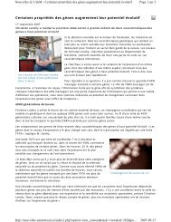
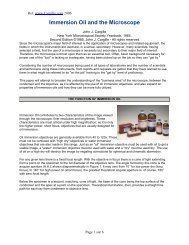
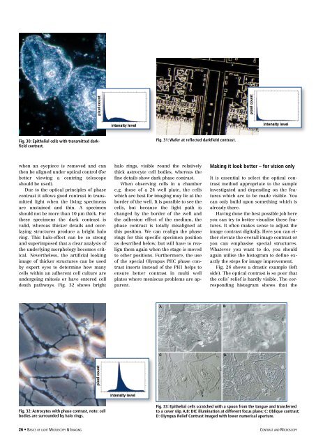
Fig. 30: Epithelial cells with transmitted darkfield<br />
contrast.<br />
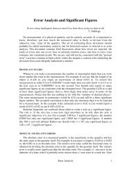
Fig. 31: Wafer at reflected darkfield contrast.<br />
when an eyepiece is removed and can<br />
then be aligned under optical control (for<br />
better viewing a centring telescope<br />
should be used).<br />
Due to the optical principles <strong>of</strong> phase<br />
contrast it allows good contrast in transmitted<br />
light when the living specimens<br />
are unstained and thin. A specimen<br />
should not be more than 10 µm thick. For<br />
these specimens the dark contrast is<br />
valid, whereas thicker details and overlaying<br />
structures produce a bright halo<br />
ring. This halo-effect can be so strong<br />
and superimposed that a clear analysis <strong>of</strong><br />
the underlying morphology becomes critical.<br />
Nevertheless, the artificial looking<br />
image <strong>of</strong> thicker structures can be used<br />
by expert eyes to determine how many<br />
cells within an adherent cell culture are<br />
undergoing mitosis or have entered cell<br />
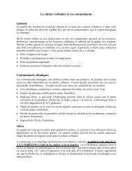
death pathways. Fig. 32 shows bright<br />
halo rings, visible round the relatively<br />
thick astrocyte cell bodies, whereas the<br />
fine details show dark phase contrast.<br />
When observing cells in a chamber<br />
e.g. those <strong>of</strong> a 24 well plate, the cells<br />
which are best for imaging may lie at the<br />
border <strong>of</strong> the well. It is possible to see the<br />
cells, but because the light path is<br />
changed by the border <strong>of</strong> the well and<br />
the adhesion effect <strong>of</strong> the medium, the<br />
phase contrast is totally misaligned at<br />
this position. We can realign the phase<br />
rings for this specific specimen position<br />
as described below, but will have to realign<br />
them again when the stage is moved<br />
to other positions. Furthermore, the use<br />
<strong>of</strong> the special Olympus PHC phase contrast<br />
inserts instead <strong>of</strong> the PH1 helps to<br />
ensure better contrast in multi well<br />
plates where meniscus problems are apparent.<br />
Making it look better – for vision only<br />
It is essential to select the optical contrast<br />
method appropriate to the sample<br />
investigated and depending on the features<br />
which are to be made visible. You<br />
can only build upon something which is<br />
already there.<br />
Having done the best possible job here<br />
you can try to better visualise these features.<br />
It <strong>of</strong>ten makes sense to adjust the<br />
image contrast digitally. Here you can either<br />
elevate the overall image contrast or<br />
you can emphasise special structures.<br />
Whatever you want to do, you should<br />
again utilise the histogram to define exactly<br />
the steps for image improvement.<br />
Fig. 28 shows a drastic example (left<br />
side). The optical contrast is so poor that<br />
the cells’ relief is hardly visible. The corresponding<br />
histogram shows that the<br />
Fig. 32: Astrocytes with phase contrast, note: cell<br />
bodies are surrounded by halo rings.<br />
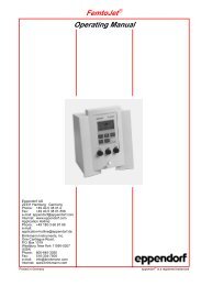
Fig. 33: Epithelial cells scratched with a spoon from the tongue and transferred<br />
to a cover slip. A,B: DIC illumination at different focus plane; C: Oblique contrast;<br />
D: Olympus Relief Contrast imaged with lower numerical aperture.<br />
26 • <strong>Basics</strong> <strong>of</strong> light <strong>Microscopy</strong> & <strong>Imaging</strong> contrast and <strong>Microscopy</strong>