Basics of Light Microscopy Imaging - AOMF
Basics of Light Microscopy Imaging - AOMF
Basics of Light Microscopy Imaging - AOMF

You also want an ePaper? Increase the reach of your titles
YUMPU automatically turns print PDFs into web optimized ePapers that Google loves.
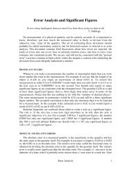
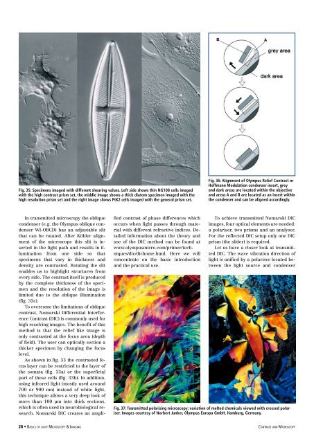
Fig. 35: Specimens imaged with different shearing values. Left side shows thin NG108 cells imaged<br />
with the high contrast prism set, the middle image shows a thick diatom specimen imaged with the<br />
high resolution prism set and the right image shows PtK2 cells imaged with the general prism set.<br />
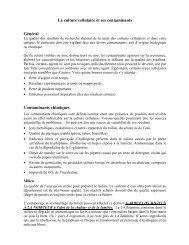
Fig. 36: Alignment <strong>of</strong> Olympus Relief Contrast or<br />
H<strong>of</strong>fmann Modulation condenser insert, grey<br />
and dark areas are located within the objective<br />
and areas A and B are located as an insert within<br />
the condenser and can be aligned accordingly.<br />
In transmitted microscopy the oblique<br />
condenser (e.g. the Olympus oblique condenser<br />
WI-OBCD) has an adjustable slit<br />
that can be rotated. After Köhler alignment<br />
<strong>of</strong> the microscope this slit is inserted<br />
in the light path and results in illumination<br />
from one side so that<br />
specimens that vary in thickness and<br />
density are contrasted. Rotating the slit<br />
enables us to highlight structures from<br />
every side. The contrast itself is produced<br />
by the complete thickness <strong>of</strong> the specimen<br />
and the resolution <strong>of</strong> the image is<br />
limited due to the oblique illumination<br />
(fig. 33c).<br />
To overcome the limitations <strong>of</strong> oblique<br />
contrast, Nomarski Differential Interference<br />
Contrast (DIC) is commonly used for<br />
high resolving images. The benefit <strong>of</strong> this<br />
method is that the relief like image is<br />
only contrasted at the focus area (depth<br />
<strong>of</strong> field). The user can optically section a<br />
thicker specimen by changing the focus<br />
level.<br />
As shown in fig. 33 the contrasted focus<br />
layer can be restricted to the layer <strong>of</strong><br />
the somata (fig. 33a) or the superficial<br />
part <strong>of</strong> these cells (fig. 33b). In addition,<br />
using infrared light (mostly used around<br />
700 or 900 nm) instead <strong>of</strong> white light,<br />
this technique allows a very deep look <strong>of</strong><br />
more than 100 µm into thick sections,<br />
which is <strong>of</strong>ten used in neurobiological research.<br />
Nomarski DIC creates an amplified<br />
contrast <strong>of</strong> phase differences which<br />
occurs when light passes through material<br />
with different refractive indices. Detailed<br />
information about the theory and<br />
use <strong>of</strong> the DIC method can be found at<br />
www.olympusmicro.com/primer/techniques/dic/dichome.html.<br />
Here we will<br />
concentrate on the basic introduction<br />
and the practical use.<br />
To achieve transmitted Nomarski DIC<br />
images, four optical elements are needed:<br />
a polariser, two prisms and an analyser.<br />
For the reflected DIC setup only one DIC<br />
prism (the slider) is required.<br />
Let us have a closer look at transmitted<br />
DIC. The wave vibration direction <strong>of</strong><br />
light is unified by a polariser located between<br />
the light source and condenser<br />
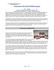
Fig. 37: Transmitted polarising microscopy; variation <strong>of</strong> melted chemicals viewed with crossed polariser.<br />
Images courtesy <strong>of</strong> Norbert Junker, Olympus Europa GmbH, Hamburg, Germany.<br />
28 • <strong>Basics</strong> <strong>of</strong> light <strong>Microscopy</strong> & <strong>Imaging</strong> contrast and <strong>Microscopy</strong>