Basics of Light Microscopy Imaging - AOMF
Basics of Light Microscopy Imaging - AOMF
Basics of Light Microscopy Imaging - AOMF

You also want an ePaper? Increase the reach of your titles
YUMPU automatically turns print PDFs into web optimized ePapers that Google loves.
fraction differences at various parts <strong>of</strong><br />
the specimen shape are used for contrast<br />
enhancement. It allows semi-transparent<br />
specimens structures to be analysed in a<br />
manner difficult to achieve using bright<br />
field microscopy. (See also<br />
www.olympusmicro.com/primer/techniques/<br />
h<strong>of</strong>fmanindex.html).<br />
For this contrast technique a special<br />
condenser and objective are needed. In<br />
advanced systems the condenser is<br />
equipped with a polariser and a condenser<br />
slit plate (according to the objective<br />
in use, fig. 36 A and B area). The<br />
achromatic or fluorite objective contains<br />
a modulator insert at one side <strong>of</strong> the back<br />
focal plane (fig. 36 dark and grey area).<br />
The slit plate at the condenser has to be<br />
aligned according to the modulator<br />
within the objective (fig. 36). This can be<br />
done by visualising these elements via a<br />
focused centring telescope (remove one<br />
eyepiece and insert the telescope). The<br />
resulting contrast can be varied by rotating<br />
the polariser at the condenser.<br />
The interpretation <strong>of</strong> DIC and relief<br />
contrast images is not intuitive. These<br />
techniques contrast different refractive<br />
indices within a specimen into a pseudothree-dimensional<br />
image. This means<br />
that specimen details which look like<br />
holes or hills on the surface <strong>of</strong> a structure<br />
(see fig. 35 left and right side) may<br />
simply be areas <strong>of</strong> different refraction index<br />
but not necessarily different in<br />
height.<br />
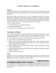
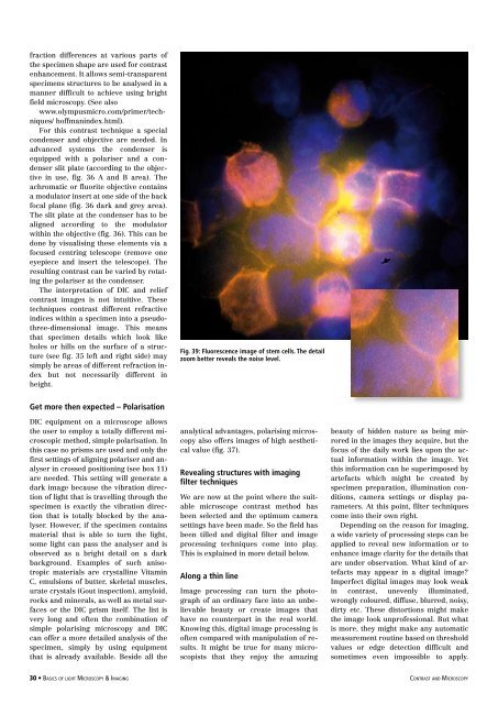
Fig. 39: Fluorescence image <strong>of</strong> stem cells. The detail<br />
zoom better reveals the noise level.<br />
Get more then expected – Polarisation<br />
DIC equipment on a microscope allows<br />
the user to employ a totally different microscopic<br />
method, simple polarisation. In<br />
this case no prisms are used and only the<br />
first settings <strong>of</strong> aligning polariser and analyser<br />
in crossed positioning (see box 11)<br />
are needed. This setting will generate a<br />
dark image because the vibration direction<br />
<strong>of</strong> light that is travelling through the<br />
specimen is exactly the vibration direction<br />
that is totally blocked by the analyser.<br />
However, if the specimen contains<br />
material that is able to turn the light,<br />
some light can pass the analyser and is<br />
observed as a bright detail on a dark<br />
background. Examples <strong>of</strong> such anisotropic<br />
materials are crystalline Vitamin<br />
C, emulsions <strong>of</strong> butter, skeletal muscles,<br />
urate crystals (Gout inspection), amyloid,<br />
rocks and minerals, as well as metal surfaces<br />
or the DIC prism itself. The list is<br />
very long and <strong>of</strong>ten the combination <strong>of</strong><br />
simple polarising microscopy and DIC<br />
can <strong>of</strong>fer a more detailed analysis <strong>of</strong> the<br />
specimen, simply by using equipment<br />
that is already available. Beside all the<br />
analytical advantages, polarising microscopy<br />
also <strong>of</strong>fers images <strong>of</strong> high aesthetical<br />
value (fig. 37).<br />
Revealing structures with imaging<br />
filter techniques<br />
We are now at the point where the suitable<br />
microscope contrast method has<br />
been selected and the optimum camera<br />
settings have been made. So the field has<br />
been tilled and digital filter and image<br />
processing techniques come into play.<br />
This is explained in more detail below.<br />
Along a thin line<br />
Image processing can turn the photograph<br />
<strong>of</strong> an ordinary face into an unbelievable<br />
beauty or create images that<br />
have no counterpart in the real world.<br />
Knowing this, digital image processing is<br />
<strong>of</strong>ten compared with manipulation <strong>of</strong> results.<br />
It might be true for many microscopists<br />
that they enjoy the amazing<br />
beauty <strong>of</strong> hidden nature as being mirrored<br />
in the images they acquire, but the<br />
focus <strong>of</strong> the daily work lies upon the actual<br />
information within the image. Yet<br />
this information can be superimposed by<br />
artefacts which might be created by<br />
specimen preparation, illumination conditions,<br />
camera settings or display parameters.<br />
At this point, filter techniques<br />
come into their own right.<br />
Depending on the reason for imaging,<br />
a wide variety <strong>of</strong> processing steps can be<br />
applied to reveal new information or to<br />
enhance image clarity for the details that<br />
are under observation. What kind <strong>of</strong> artefacts<br />
may appear in a digital image<br />
Imperfect digital images may look weak<br />
in contrast, unevenly illuminated,<br />
wrongly coloured, diffuse, blurred, noisy,<br />
dirty etc. These distortions might make<br />
the image look unpr<strong>of</strong>essional. But what<br />
is more, they might make any automatic<br />
measurement routine based on threshold<br />
values or edge detection difficult and<br />
sometimes even impossible to apply.<br />
30 • <strong>Basics</strong> <strong>of</strong> light <strong>Microscopy</strong> & <strong>Imaging</strong> contrast and <strong>Microscopy</strong>