Basics of Light Microscopy Imaging - AOMF
Basics of Light Microscopy Imaging - AOMF
Basics of Light Microscopy Imaging - AOMF

Create successful ePaper yourself
Turn your PDF publications into a flip-book with our unique Google optimized e-Paper software.
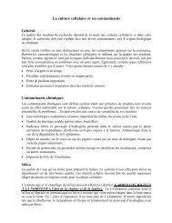
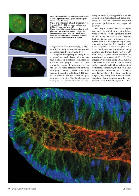
Fig. 62: Human breast cancer tissue labelled with<br />
a probe against the HER2-gene (Texas Red) and<br />
Chromosome 17 (FITC).<br />
Upper left: Maximum intensity projection <strong>of</strong> 25<br />
frames, λ(FITC) = 518 nm, numerical aperture<br />
(NA) = 1, z spacing (Δz) = 0.18.<br />
Upper right: Blind deconvolution applied to both<br />
channels. Left: Maximum intensity projection.<br />
When the volume-rendered structure is seen<br />
from two different angles, the spatial composition<br />
<strong>of</strong> the fluorescence signals is shown.<br />
computerised axial tomography, (CAT) –<br />
familiar to many in medical applications<br />
as Computerised Tomography (CT).<br />
Computer tomography has long been<br />
a part <strong>of</strong> the standard repertoire for routine<br />
medical applications. Transmission<br />
electron tomography, however, has<br />
grown increasingly important as well in<br />
the last few years. Transmission electron<br />
tomography made possible what had<br />
seemed impossible in biology: 3-D imaging<br />
<strong>of</strong> interior cellular structures, just<br />
nanometres in size. This has become a<br />
reality due to a combination <strong>of</strong> new technologies<br />
– suitably equipped electron microscopes,<br />
high resolving and highly sensitive<br />
CCD cameras, increased computer<br />
processor performance and improved<br />
s<strong>of</strong>tware.<br />
The way in which electron tomography<br />
works is actually quite straightforward<br />
(see box 17). The specimen holder<br />
is tilted along an eucentric* axis (if possible)<br />
and in the process, images are acquired<br />
from a wide range <strong>of</strong> angles. This<br />
guarantees that the 3-D structure will<br />
have adequate resolution along the three<br />
axes. Usually the specimen is tilted along<br />
a single axis from at least – 60° to + 60°<br />
with images (projections) recorded at<br />
equidistant increments <strong>of</strong> 1° or 2°. The<br />
images are acquired using a CCD camera<br />
and stored as a tilt stack. Due to effects<br />
such as sample shift, tilt <strong>of</strong> axis position<br />
or thermal expansion, the tilt stack has<br />
to be aligned before further processing<br />
can begin. Once the stack has been<br />
aligned, it is ready to be used for reconstruction.<br />
Reconstruction can be performed<br />
using different approaches. Two<br />
48 • <strong>Basics</strong> <strong>of</strong> light <strong>Microscopy</strong> & <strong>Imaging</strong> 3D <strong>Imaging</strong>