mpeg4 4ch dvr manuall
mpeg4 4ch dvr manuall
mpeg4 4ch dvr manuall

Create successful ePaper yourself
Turn your PDF publications into a flip-book with our unique Google optimized e-Paper software.
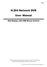
260Z<br />
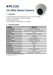
MPEG4 4CH DVR<br />
MANUAL<br />
REC PLAY PA USE ST OP REW<br />
FF<br />
HD D<br />
HD D Fu ll<br />
ALAR M<br />
TIMER<br />
PLAY<br />
RE C<br />
MENU<br />
ENTER<br />
LIST<br />
SLOW<br />
ZOOM<br />
SEQ<br />
Please read instructions thoroughly before operation and retain it for future reference.<br />
The image shown above may differ from the actual product appearance.<br />
DR040_Manual_V1.0
IMPORTANT SAFEGUARD<br />
CAUTION<br />
RISK OF ELECTRIC SHOCK<br />
CAUTION:<br />
To reduce the risk of electric shock, do not expose this apparatus to rain or moisture.<br />
Only operate this apparatus from the type of power source indicated on the label.<br />
The company shall not be liable for any damages arising out of any improper use,<br />
even if we have been advised of the possibility of such damages.<br />
Graphic Symbol Explanation<br />
The lightning flash with arrowhead symbol, within an equilateral triangle, is intended to alert the user<br />
to the presence of uninsulated “dangerous voltage” within the product’s enclosure that may be of<br />
sufficient magnitude to constitute a risk of electric shock to persons.<br />
This exclamation point within an equilateral triangle is intended to alert the user to the presence of<br />
important operating and maintenance (servicing) instructions in the literature accompanying the<br />
appliance.<br />
All lead-free products offered by the company comply with the requirements of the European law on<br />
the Restriction of Hazardous Substances (RoHS) directive, which means our manufacture processes<br />
and products are strictly “lead-free” and without the hazardous substances cited in the directive.<br />
The crossed-out wheeled bin mark symbolizes that within the European Union the product must be<br />
collected separately at the product end-of-life. This applies to your product and any peripherals<br />
marked with this symbol. Do not dispose of these products as unsorted municipal waste. Contact your<br />
local dealer for procedures for recycling this equipment.<br />
This apparatus is manufactured to comply with the radio interference requirements.<br />
Disclaimer<br />
We reserve the right to revise or remove any content in this manual at any time. We do not warrant or assume any<br />
legal liability or responsibility for the accuracy, completeness, or usefulness of this manual. The content of this manual<br />
is subject to change without notice.<br />
MPEG4 Licensing<br />
THIS PRODUCT IS LICENSED UNDER THE MPEG-4 VISUAL PATENT PORTFOLIO LICENSE FOR THE<br />
PERSONAL AND NON-COMMERCIAL USE OF A CONSUMER FOR (i) ENCODING VIDEO IN COMPLIANCE WITH<br />
THE MPEG-4 VISUAL STANDARD (“MPEG-4 VIDEO”) AND/OR (ii) DECODING MPEG-4 VIDEO THAT WAS<br />
ENCODED BY A CONSUMER ENGAGED IN A PERSONAL AND NON-COMMERCIAL ACTIVITY AND/OR WAS<br />
OBTAINED FROM A VIDEO PROVIDER LICENSED BY MPEG LA TO PROVIDE MPEG-4 VIDEO. NO LICENSE IS<br />
GRANTED OR SHALL BE IMPLIED FOR ANY OTHER USE. ADDITIONAL INFORMATION INCLUDING THAT<br />
RELATING TO PROMOTIONAL INTERNAL AND COMMERCIAL USES AND LICENSING MAY BE OBTAINED FROM<br />
MPEG LA, LLC. SEE HTTP://WWW.MPEGLA.COM.<br />
Version<br />
Firmware: 1167-1012-1022-1017<br />
Licensed Software AP: 0075
TABLE OF CONTENTS<br />
1. OVERVIEW............................................................................................................................... 1<br />
1.1 Product Description .........................................................................................................................................1<br />
1.2 Features...........................................................................................................................................................1<br />
1.3 Package Contents ...........................................................................................................................................1<br />
1.4 Specifications...................................................................................................................................................2<br />
2. FRONT AND REAR PANELS .................................................................................................. 3<br />
2.1 Front Panel ......................................................................................................................................................3<br />
2.2 Rear Panel.......................................................................................................................................................5<br />
3. CONNECTIONS AND SETUP.................................................................................................. 6<br />
3.1 HDD Installation...............................................................................................................................................6<br />
3.2 Camera Connection.........................................................................................................................................6<br />
3.3 Power Setup ....................................................................................................................................................6<br />
3.4 Date and Time Setting .....................................................................................................................................6<br />
3.5 Password Setting.............................................................................................................................................6<br />
4. BASIC OPERATION................................................................................................................. 8<br />
4.1 Live Page.........................................................................................................................................................8<br />
4.2 Recording ........................................................................................................................................................8<br />
4.3 Playback ..........................................................................................................................................................8<br />
4.4 Key Lock and Unlock .......................................................................................................................................9<br />
4.5 Upgrade...........................................................................................................................................................9<br />
4.6 Search ...........................................................................................................................................................10<br />
5. MENU CONFIGURATION ...................................................................................................... 11<br />
6. QUICK START MENU ............................................................................................................ 12<br />
6.1 QUICK SEARCH ...........................................................................................................................................12<br />
6.2 RECORD .......................................................................................................................................................12<br />
6.2 TIMER............................................................................................................................................................14<br />
6.3 Date ...............................................................................................................................................................14<br />
7. ADVANCED MENU ................................................................................................................15<br />
7.1 CAMERA .......................................................................................................................................................15<br />
7.2 DETECTION ..................................................................................................................................................16<br />
(1) Detection Setup................................................................................................................................16<br />
(2) Detection Timer................................................................................................................................17<br />
7.3 DISPLAY........................................................................................................................................................18<br />
7.4 ALERT ...........................................................................................................................................................18<br />
7.5 SYSTEM........................................................................................................................................................19<br />
7.6 NETWORK ....................................................................................................................................................20<br />
7.7 BACKUP........................................................................................................................................................22<br />
7.8 HDD INFO .....................................................................................................................................................23<br />
7.9 EVENT LOG ..................................................................................................................................................24<br />
8. REMOTE OPERATION .......................................................................................................... 25<br />
8.1 Supplied Licensed Software AP.....................................................................................................................25<br />
8.1.1 Installation & Network Connection .......................................................................................................25
8.1.2 General AP Operation..........................................................................................................................26<br />
Record...................................................................................................................................................26<br />
Playback................................................................................................................................................27<br />
Network Backup ....................................................................................................................................28<br />
8.1.3 AP Control Panel .................................................................................................................................28<br />
8.1.4 AP Functions........................................................................................................................................30<br />
Image Display........................................................................................................................................30<br />
Address Book ........................................................................................................................................30<br />
Miscellaneous Control ...........................................................................................................................32<br />
Information ............................................................................................................................................49<br />
DVR Control ..........................................................................................................................................49<br />
8.2 IE Web Browser.............................................................................................................................................51<br />
8.3 QuickTime Player...........................................................................................................................................52<br />
APPENDIX 1 COMPATIBLE USB FLASH DRIVE BRAND....................................................... 53<br />
APPENDIX 2 COMPATIBLE HDD BRAND................................................................................ 54<br />
APPENDIX 3 TROUBLESHOOTING ......................................................................................... 55<br />
APPENDIX 4 DEFAULT VALUE ................................................................................................ 56
OVERVIEW<br />
1. OVERVIEW<br />
1.1 Product Description<br />
This MPEG4 multiplex network DVR series combines remote surveillance, burglar prevention, and evidentiary<br />
recording features and is designed to become a simple entry-level system with all necessary functions.<br />
1.2 Features<br />
• MPEG4 Network Transmission<br />
‧ MPEG4 web transmitting for faster transmission and clearer images via network<br />
• Simplex / Duplex Operation<br />
‧ Simplex / Duplex selectable for live record, playback, backup and network operation<br />
• Free upgrade to advanced functions<br />
‧ Allows you to upgrade DVR functions without any charges<br />
• Backup function<br />
‧ Supports USB 2.0 flash drive and network remote backup<br />
• Remote surveillance<br />
‧ Supports remote surveillance up to 20 users simultaneously via the licensed software AP & IE web browser<br />
• Intelligent motion trigger recording<br />
‧ With the advanced functions of motion detection (4 different adjustable factors for motion detection sensitivity)<br />
‧ Supports pre-alarm recording (2MB)<br />
• Covert recording<br />
‧ Blank screen replaces live displays to achieve covert recording<br />
• A/V support<br />
‧ Supports 1 audio-in, 1 audio-out to record sounds<br />
• General<br />
‧ System auto recovery after power failure<br />
‧ Supports auto video system detection (NTSC / PAL)<br />
‧ Supports daylight saving function<br />
‧ Supports TCP/IP, PPPOE, DHCP and DDNS network connection<br />
1.3 Package Contents<br />
□ Digital video recorder (DVR)<br />
□ Thermal conductive silicone rubber<br />
□ Adapter and power cord<br />
□ HDD bracket screws (spare parts)<br />
□ Free licensed software AP disc<br />
□ DSUB PIN connector<br />
□ Manual & quick start & IR remote control manual □ AAA size battery * 2<br />
□ Vertical panel sticker for remote controller (certain models only)<br />
-1-
1.4 Specifications<br />
OVERVIEW<br />
MODEL<br />
DR040<br />
Video System<br />
Video Compression Format<br />
Video Input (Composite video signal 1 Vp-p 75Ω BNC)<br />
Video Output<br />
Maximum Recording Rate (CIF)<br />
Adjustable Recording Speed (CIF)<br />
Multilingual OSD<br />
Image Quality Setting<br />
Hard Disk Storage (HDD is optional)<br />
HDD Quick Cleaning<br />
Recording Mode<br />
Refresh Rate<br />
Operation Modes<br />
Audio I/O<br />
Motion Detection Area<br />
Motion Detection Sensitivity<br />
Backup Device<br />
NTSC / PAL (auto detection)<br />
MPEG4<br />
4 Channels<br />
Composite video signal 1 Vp-p 75Ω BNC<br />
Simplex Mode: 360×240 pixels with 120 IPS /<br />
360×288 pixels with 100 IPS <br />
Duplex Mode: 360×240 pixels with 40 IPS /<br />
360×288 pixels with 32 IPS <br />
Simplex Mode: 120, 60, 30 IPS / 100, 50, 25 IPS <br />
Duplex Mode: 40, 28, 20 IPS / 32, 24, 16 IPS <br />
YES<br />
Best / High / Normal / Basic<br />
Accommodate 1 HDD<br />
Quick clean up the “index system” of the recorded files<br />
(750GB under 2 seconds)<br />
Manual / Timer / Motion / Remote<br />
120 IPS for NTSC / 100 IPS for PAL<br />
Simplex / Duplex selectable<br />
*Live Record / Playback / Backup / Network<br />
1 audio input, 1 audio output (Mono)<br />
16 × 12 grids per camera for all channels<br />
4 adjustable variables with precise calculation for motion detection<br />
USB 2.0 flash drive<br />
USB Interface Rear panel * 1<br />
Web Transmitting Compression Format<br />
Ethernet<br />
Remote Operation Software<br />
Remote Alarm Notification<br />
Network Protocol<br />
Key Lock<br />
Video Loss Detection<br />
Camera Title<br />
Video Adjustable<br />
Date Display Format<br />
Daylight Saving<br />
Power Source<br />
Power Consumption<br />
MPEG4<br />
10/100 Base-T. Support remote control and live view via Ethernet<br />
Licensed software AP, IE browser<br />
*Operating System: Windows 2000, Windows XP and Vista<br />
Email images, and upload images to FTP site’s specific account<br />
TCP/IP / PPPOE / DHCP / DDNS<br />
YES<br />
YES<br />
Support up to 6 letters<br />
Hue / Color / Contrast / Brightness<br />
YY/MM/DD, DD/MM/YY, MM/DD/YY, and OFF<br />
YES<br />
DC 19V<br />
FRONT AND REAR PANELS<br />
2. FRONT AND REAR PANELS<br />
REC PLAY PA USE ST OP REW<br />
FF<br />
HD D<br />
HD D Fu ll<br />
ALAR M<br />
TIMER<br />
PLAY<br />
RE C<br />
MENU<br />
ENTER<br />
LIST<br />
SLOW<br />
ZOOM<br />
SEQ<br />
2.1 Front Panel<br />
1) LED Indication<br />
The following LEDs will be on when:<br />
HDD: HDD is reading or recording<br />
HDD Full: HDD is full<br />
ALARM: Any motion detection is triggered.<br />
TIMER: Timer recording is activated<br />
PLAY: DVR is under playback mode<br />
REC: DVR is under recording mode<br />
: Power is connected<br />
Note: To turn off your DVR, please disconnect the power supply.<br />
2) 1 / 2 / 3 / 4<br />
Press one of these buttons to show the channel display of CH1 ~ CH4 on the monitor.<br />
3) REC<br />
Press this button to activate manual recording.<br />
4) PLAY<br />
Press this button to play the latest recorded video.<br />
5) PAUSE / STOP / REW / FF<br />
Under the playback mode:<br />
Press one of these button to pause / stop / rewind / fast-forward the playback file.<br />
6) ▲+ / ▼- / ◄ / ►<br />
Press one of these direction buttons to move the cursor up/down/left/right.<br />
Under the DVR menu mode, these direction buttons can use for the following operation:<br />
▲▼: Make the selection / Change the settings<br />
◄ ►: Make the selection<br />
7) MENU<br />
Press this button to enter / exit the DVR menu mode.<br />
In the sub-layer of the DVR menu, press this button to confirm the settings and go back to the upper layer.<br />
8) ENTER<br />
Confirm the password entering.<br />
-3-
FRONT AND REAR PANELS<br />
9) LIST (Event List Search)<br />
To quick search the recorded files by event list, press this button to show all types of the event lists.<br />
Select one of the event list and press “ENTER” button to playback the selected file.<br />
MANUAL: List the information of the manual-recorded files. The DVR will save one recorded file once any recording setting is changed<br />
SYSTEM: List the information of the system-recorded files. The DVR system will save one recorded file every one hour.<br />
MOTION: List the information of the motion-trigger-recorded files.<br />
TIMER: List the information of the timer-recorded files.<br />
10) SLOW<br />
Under the playback mode, press this button to slowly playback the recorded file (by 1/4 speed or 1/8 speed).<br />
11) ZOOM<br />
In the live mode of the DVR, press this button to enlarge the image of the selected channel.<br />
12) (Quad Display)<br />
Press this button to show the quad display mode on the monitor.<br />
Note: If you want to make a video backup with audio, please connect audio camera to the CH1 which<br />
support the audio function<br />
13) “MENU” + “ENTER” (Key lock)<br />
Press these two buttons at the same time to lock keys on the DVR front panel.<br />
-4-
CONNECTIONS AND SETUP<br />
2.2 Rear Panel<br />
RISKOF ELECTRIC SHOCK<br />
DO NOT OPEN<br />
USB<br />
1 2 3 4 OUT IN OUT<br />
LINK<br />
ACT.<br />
WARNI N G : TO RED UCE THE RISK OF ELECTRIC SHOCK,<br />
DO N OT R E M OV E CO V ER (O R BA CK ).<br />
NO USER -SE R VIC E ABL E PA RT S INSI D E.<br />
REFER SERV IC IN G TO Q U ALI F IED<br />
S ER V IC E PE R SO NN EL.<br />
LAN<br />
DC 19V<br />
1) USB Port<br />
To quickly backup or upgrade firmware/OSD, you can insert a compatible USB flash drive into this USB port.<br />
Before using the USB flash drive, please use your PC to format the USB flash drive as “FAT32” first.<br />
Note: For the list of compatible USB flash drives, please refer to “APPENDIX 1 COMPATIBLE USB FLASH<br />
DRIVE BRAND” at page 53.<br />
2) VIDEO INPUT (1 ~ 4CH)<br />
Connect to video sources, such as cameras.<br />
Note: If you want to make a video backup with audio, please connect audio camera to CH1 which<br />
supports the audio function.<br />
3) VIDEO OUTPUT<br />
Connect to a CRT monitor for video output.<br />
4) AUDIO IN (1)<br />
Connect to audio source, such as camera equipped with the audio function.<br />
When users start recording, the audio input will also be recorded with corresponding video channel.<br />
Note: The audio source connected to the “Audio 1” will be recorded with the video of the “CH1”.<br />
5) Audio OUT (1)<br />
Connect to a monitor or speaker with 1 mono audio output.<br />
6) LAN<br />
Connect to Internet by LAN cable.<br />
7) LINK ACT.<br />
When your DVR is connected to the Internet, this LED will be on.<br />
8) DC 19V<br />
Connect to the supplied adapter.<br />
-5-
CONNECTIONS AND SETUP<br />
3. CONNECTIONS AND SETUP<br />
3.1 HDD Installation<br />
The HDD must be installed before the DVR is turned on.<br />
Step 1: Loose the screws on the upper cover and open the upper cover of the DVR.<br />
Step 2: Remove the HDD bracket.<br />
Step 3: Get a suitable brand HDD and set the HDD mode to “Master” mode.<br />
Step 4: Slide and fasten the HDD to the HDD bracket, two screws for each side.<br />
Step 5: Replace the HDD bracket back to the DVR base.<br />
Step 6: Connect the HDD to the power connector and the IDE BUS connector<br />
(make sure to align the HDD precisely for pin connection).<br />
Step 7: Close the upper cover of the DVR, and fasten all the screws you loosened in Step 1.<br />
3.2 Camera Connection<br />
The cameras must be connected and power-supplied BEFORE the DVR is turned on. The DVR will automatically<br />
detect the video system of the connected camera(s) (NTSC / PAL), and switch itself to the correct system.<br />
Connect the camera with the indicated power supply, and connect the camera video output to the DVR video input<br />
port with a coaxial cable or RCA lines with BNC connectors.<br />
Note: For detailed DVR video input / output ports, please refer to “2.2 Rear Panel” at page 5.<br />
For detailed camera operation, please refer to its own manual.<br />
Note: If you want to make a video backup with audio, please connect audio camera to the CH1 which<br />
support the audio function<br />
3.3 Power Setup<br />
This device should be operated only with the type of power source indicated on the manufacturer’s label. Connect<br />
the indicated AC power cord to the power adapter, and plug into an electrical outlet. The power LED “ ” will be on as<br />
green. It takes approximately 10 to 15 seconds to boot the system.<br />
3.4 Date and Time Setting<br />
Before operating your DVR, please set the date and time on your DVR first.<br />
Press the “MENU” button and enter the password to go to the menu list. The default admin password is 0000.<br />
Move the cursor to “DATE” and you can set the date / time / daylight saving in the “DATE” menu list.<br />
3.5 Password Setting<br />
Press the “MENU” button and enter the password to go to the menu list. Then, move the cursor to “ADVANCE” to<br />
enter the advanced setting menu.<br />
In the “ADVANCE” menu, move the cursor to “SYSTEM”. Select “PASSWORD” and press the “ENTER” button to<br />
enter the submenu to set the password (four digits). The default admin password is 0000.<br />
-6-
CONNECTIONS AND SETUP<br />
ADVANCE<br />
SYSTEM<br />
CAMERA PASSWORD XXXX<br />
DETECTION RESET DEFAULT RESET<br />
DISPLAY CLEAR HDD HDD-MASTER-1<br />
ALERT UPGRADE START<br />
SYSTEM AUTO KEYLOCK NEVER<br />
NETWORK LANGUAGE ENGLISH<br />
BACKUP VIDEO FORMAT NTSC<br />
HDD INFO VERSION 1167-1012-1022-1017<br />
-7-
BASIC OPERATION<br />
4. BASIC OPERATION<br />
4.1 Live Page<br />
In this live page of the DVR, you can see the following icons:<br />
Icon Function Icon Function Icon Function Icon Function<br />
Key lock<br />
Key unlock<br />
1 st live audio<br />
channel<br />
Digital zoom mode<br />
Digital zoom<br />
unselected<br />
Timer recording Motion Recording<br />
4.2 Recording<br />
When the recording and the pre-alarm function are activated, this device will overwrite 8GB data from the oldest<br />
for continuous recording without notice.<br />
1) Continuous Recording Icon<br />
When the DVR is properly connected with camera, you can see the icon “<br />
” (recording) on the monitor.<br />
2) Motion Recording Icon<br />
When the motion / alarm detection is activated, once motion or external alarm happens, you will see the icon<br />
“ ” (motion) on the monitor.<br />
3) Timer Recording Icon<br />
When the timer record is activated, you will see the icon “<br />
” (timer) on the monitor<br />
Note: The audio source connected to the “Audio 1” will be recorded with the video of the “CH1”.<br />
4.3 Playback<br />
Press the “PLAY” button on the DVR control panel, and the device will playback the latest recorded video.<br />
Note: There must be at least 8192 images of recorded data for playback to work properly. If not, the<br />
device will stop playback. For example, if the IPS is set to 30, the recording time should be at least<br />
205 seconds (8192 images / 40 IPS) for the playback to work properly.<br />
1) Fast Forward / Fast Rewind<br />
You can increase the speed for fast forward and rewind on this device. In the playback mode:<br />
Press “FF“ once to get 4X speed forward and press twice to get 8X speed, etc. And the maximum speed is 32X.<br />
Press “REW“ once to get 4X speed rewind and press twice to get 8X speed, etc. And the maximum speed is 32X.<br />
Note: During playback, the image size of the recording (CIF) will be shown on the screen.<br />
2) Pause / Image Jog<br />
Press “PAUSE” button to pause the playback.<br />
In the pause mode:<br />
Press “►” button once to get one frame forward.<br />
Press “◄” button once to get one frame rewind.<br />
3) Stop<br />
Pressing “STOP” button under playback mode, the screen of this device will return to live monitoring mode.<br />
-8-
BASIC OPERATION<br />
4) Slow Playback<br />
Press “SLOW” button to get 1/4X speed playback and press twice to get 1/8X speed playback.<br />
5) Audio Playback<br />
Use these two buttons to select the live or playback sound of the audio channels.<br />
Icon “ ” means: Live audio of the 1 st audio channel / Icon “ ” means: Playback audio of the 1 st audio channel<br />
Note: If you want to make a video backup with audio, please connect audio camera to CH1 which support<br />
the audio function<br />
4.4 Key Lock and Unlock<br />
1) Key Lock On:<br />
Press “MENU” + “ENTER” buttons at the same time on the DVR control panel to lock keys.<br />
Or set the time-out after which the key lock function is activated (Never / 10 SEC / 30 SEC / 60 SEC). Please refer<br />
to “7.5 SYSTEM” at page 19.<br />
2) Key Lock Off:<br />
Enter the DVR password to exit “Key Lock” mode.<br />
Note: For the password setting, please refer to the section “3.5 Password Setting” at page 6.<br />
4.5 Upgrade<br />
‧ Firmware / Multilanguage OSD Upgrade<br />
1) Use USB to upgrade firmware or OSD:<br />
Step 1. Format the USB memory device as FAT32 format first.<br />
Step 2. Get the upgrade files from your distributor and save the upgrade files in your USB flash device (do not<br />
change the file name).<br />
Step 3. In the “SYSTEM” menu, move the cursor to “UPGRADE”, and press “ENTER” button.<br />
Step 4. Select “YES”, and press “ENTER” button again to confirm upgrade.<br />
2) Use AP software to remotely upgrade firmware or OSD:<br />
Step 1. Save the upgrade files at your PC (do not change the file name) and then login to the AP software.<br />
Step 2. Press “<br />
” (Miscellaneous Control) button to show the miscellaneous control panel. In the miscellaneous<br />
control panel, press “<br />
” (Tools) button on the miscellaneous control panel to enter the AP upgrade<br />
window.<br />
Step 3. Enter the user name, password, IP address and port number of the DVR.<br />
Step 4. Press “Firmware” or “Language” tab as needed, and press “Add” to select the firmware or OSD files to<br />
upgrade.<br />
Step 5. Press “Update Firmware” or “Update Language” button to start the upgrade.<br />
Note: For remote upgrade details, please see “Tools” at page 45.<br />
-9-
BASIC OPERATION<br />
4.6 Search<br />
1) Search by List<br />
Press “LIST” button on the DVR control panel to show the list for all types of the recorded files. Choose the list<br />
you want to view and press “ENTER” button to start playback.<br />
MANUAL<br />
MOTION<br />
SYSTEM<br />
TIMER<br />
List the information of the manual-recorded files. The DVR will save one recorded file once<br />
any recording setting is changed<br />
List the information of the motion-trigger-recorded files.<br />
List the information of the system-recorded files. The DVR system will save one recorded<br />
file every one hour.<br />
List the information of the timer-recorded files.<br />
2) Quick Search by Time<br />
Press the “MENU” button to enter the menu list, move the cursor to “QUICK SEARCH”, and press “ENTER”<br />
button to enter the quick time search menu. You can search any specific events by time (Year / Month / Day / Hour<br />
/ Min) and directly play the file you find.<br />
3) Search the Record Event by Log on the AP Software<br />
Press “<br />
” (Miscellaneous Control) button to show the miscellaneous control panel. In the miscellaneous control<br />
panel, press “<br />
” (Status List) button to enter the “Status List” page. In this page, you can see the list of three<br />
different types of recording (User / Motion / Alarm) and press “Play” button to directly playback the file.<br />
-10-
MAIN MENU<br />
5. MENU CONFIGURATION<br />
MAIN MENU<br />
ASDVANCED MENU<br />
QUICK SEARCH<br />
RECORD<br />
TIMER<br />
DATE<br />
ADVANCE<br />
CAMERA<br />
DETECTION<br />
DISPLAY<br />
ALERT<br />
SYSTEM<br />
NETWORK<br />
BACKUP<br />
HDD INFO<br />
EVENT LOG<br />
DATE<br />
SEARCH HDD<br />
IMAGE SIZE<br />
QUALITY<br />
MANUAL RECORD ENABLE<br />
EVENT REOCRD ENABLE<br />
TIMER RECORD ENABLE<br />
MULTIPLEX MODE<br />
MANUAL RECORD IPS<br />
EVENT RECORD IPS<br />
TIMER RECORD IPS<br />
RECORD TIMER<br />
DETECTION TIMER<br />
DATE<br />
FORMAT<br />
DAYLIGHT SAVING<br />
TITLE<br />
BRIG<br />
CONT<br />
SATU<br />
HUE<br />
COV.<br />
TITLE<br />
DET<br />
AREA<br />
LS<br />
SS<br />
TS<br />
RE<br />
FULL SCREEN DWELL DURATION (SEC)<br />
CHANNEL TITLE<br />
EVENT STATUS<br />
INT. BUZZER<br />
KEY BUZZER<br />
VLOSS BUZZER<br />
MOTION BUZZER<br />
ALARM DURATION (SEC)<br />
PASSWORD<br />
RESET DEFAULT<br />
CLEAR HDD<br />
UPGRADE<br />
AUTO KEYLOCK (SEC)<br />
LANGUAGE<br />
VIDEO FORMAT<br />
VERSION<br />
NETWORK TYPE<br />
IP<br />
GATEWAY<br />
NETMASK<br />
PRIMARY DNS<br />
SECONDARY DNS<br />
PORT<br />
START TIME<br />
END TIME<br />
AVAILABLE SIZE<br />
HDD NUM<br />
HDD SIZE (GB)<br />
EVENT<br />
TIME<br />
COMMENT<br />
-11-
QUICK START MENU<br />
6. QUICK START MENU<br />
Press the “MENU” button and enter the password to go to the quick-start menu list. The default admin password is<br />
0000. Users can change the password later. Please refer to “SYSTEM” at page 19.<br />
ITEM<br />
MENU<br />
▲ ▼<br />
◄ ►<br />
ENTER<br />
NEXT<br />
BACK<br />
FUNCTION<br />
Enter / exit the quick start menu<br />
Under the sub-layer of the advanced setting menu, use this button to confirm the<br />
settings and go back to the upper layer.<br />
Make the selection / Change the setting<br />
Go to the upper layer or sub-layer / Make the selection<br />
Confirm the password entering<br />
Go to the sub-layer of the advanced menu<br />
Move the cursor to this item and press the “ENTER” button to go the next page.<br />
Move the cursor to this item and press “ENTER” button to go the previous page.<br />
6.1 QUICK SEARCH<br />
In this menu list, you can search any specific events by time and directly play the file you find.<br />
Move the cursor to “QUICK SEARCH”, and press “ENTER” button.<br />
You will see a similar screen as the following:<br />
TIME SEARCH<br />
DATE 2007 / OCT / 10 21 : 30 : 00<br />
MENU SEARCH HDD ALL HDD<br />
SEARCH<br />
START<br />
RECORD<br />
TIMER<br />
DATE<br />
ADVANCE<br />
PLEASE CONSULT YOUR INSTALLER FOR ADVANCE SETTING<br />
SELECT BACK NEXT ENTER<br />
The submenu items are described below:<br />
1) DATE<br />
Select the specific time period (YEAR / MONTH / DAY / HOUR / MIN) that you want to search.<br />
2) SEARCH HDD<br />
Change to the HDD you want if there are more than 1 HDD in your DVR.<br />
3) START<br />
Move the cursor to “START” and press “ENTER” button to search and directly playback the recorded files.<br />
6.2 RECORD<br />
In this menu list, you can set record settings. Press “MENU” button on the front panel to enter the main menu list.<br />
The default admin password is 0000. Enter the default password, and press “ENTER”. Users can change the password<br />
later.<br />
Move the cursor to “RECORD”, and press ” ENTER”. The screen will show the following options:<br />
-12-
QUICK START MENU<br />
RECORD<br />
IMAGE SIZE<br />
CIF<br />
MENU QUALITY BEST<br />
QUICK SEARCH MANUAL RECORD ENABLE ON<br />
RECORD EVENT RECORD ENABLE ON<br />
TIMER TIMER RECORD ENABLE ON<br />
DATE MULTIPLEX MODE OFF<br />
ADVANCE REMOTE VIEW ON<br />
MANUAL RECORD IPS 100<br />
EVENT RECORD IPS 100<br />
TIMER RECORD IPS 100<br />
The submenu items are described below:<br />
1) IMAGE SIZE<br />
You can only select CIF.<br />
2) QUALITY<br />
PLEASE CONSULT YOUR INSTALLER FOR ADVANCE SETTING<br />
SELECT BACK NEXT ENTER<br />
Select one of the 4 quality options: BEST, HIGH, NORMAL and BASIC.<br />
3) MANUAL RECORD ENABLE<br />
Start / stop the manual recording function.<br />
4) EVENT RECORD ENABLE<br />
Start / stop the event recording function. When this function is enabled, the recording will be triggered by any<br />
motion or external alarm.<br />
5) TIMER RECORD ENABLE<br />
Start / stop the timer recording function.<br />
6) MULTIPLEX MODE<br />
Select to activate the duplex mode (ON) or activate the simplex mode (OFF) for live record, playback, backup and<br />
network operation.<br />
NOTE: The HDD data needs to be removed when you switch between the duplex mode and simplex mode.<br />
The DVR will prompt you to confirm the data deletion.<br />
7) REMOVE VIEW<br />
Allow the remote surveillance or not (ON / OFF)<br />
8) MANUAL RECORD IPS<br />
Select the images per second for MANUAL RECORD.<br />
9) EVENT RECORD IPS<br />
Select the images per second for EVENT RECORD (Recording that is triggered by alarm or motion).<br />
10) TIMER RECORD IPS<br />
Select the images per second for TIMER RECORD (Recording that is activated according to the scheduled time.).<br />
The IPS options are as following:<br />
NTSC<br />
PAL<br />
Simplex CIF 120, 60, 30 CIF 100, 50, 25<br />
Duplex CIF 40, 28, 20 CIF 32, 24, 16<br />
-13-
ADVANCED MENU<br />
6.2 TIMER<br />
Press “MENU” button on the front panel to enter the main menu list. Move the cursor to “TIMER”, and<br />
press ”ENTER”. Select to enable (ON) or disable (OFF) the recorder timer and / or detection timer functions.<br />
TIMER<br />
RECORD TIMER<br />
OFF<br />
MENU DETECTION TIMER OFF<br />
QUICK SEARCH<br />
RECORD<br />
TIMER<br />
DATE<br />
PLEASE CONSULT YOUR INSTALLER FOR ADVANCE SETTING<br />
ADVANCE SELECT BACK NEXT ENTER<br />
6.3 Date<br />
In this menu list, you can set up the system date and time for this device.<br />
Note: When the recording function is activated, please DO NOT change the date or time on your DVR.<br />
Press “MENU” button on the front panel to enter the main menu list. Move the cursor to “DATE”, and<br />
press ”ENTER”. The screen will show the following options.<br />
The submenu items are described below:<br />
DATE<br />
DATE 2008 / FEB / 15 19 : 15 : 27<br />
MENU FORMAT Y/M/D<br />
QUICK SEARCH DAYLIGHT SAVING OFF<br />
RECORD<br />
TIMER<br />
DATE<br />
PLEASE CONSULT YOUR INSTALLER FOR ADVANCE SETTING<br />
ADVANCE SELECT BACK NEXT ENTER<br />
1) DATE:<br />
Set the current date and time. The default order is “YEAR – MONTH – DATE HOUR : MIN : SEC”.<br />
2) FORMAT<br />
Select one date format from the following 3 options: Y-M-D, M-D-Y, D-M-Y.<br />
3) DAYLIGHT SAVING<br />
Specify whether to use daylight-saving time (ON / OFF). If it’s set to ON, press “ENTER” to go to its submenu for<br />
further settings. You will see a similar screen as following.<br />
DAYLIGHT SAVING<br />
START TIME 1ST - SUN - MAR 24 : 00 : 00<br />
END TIME LAST - SUN - OCT 24 : 00 : 00<br />
ADJUST 01 : 00<br />
PLEASE CONSULT YOUR INSTALLER FOR ADVANCE SETTING<br />
SELECT BACK NEXT ENTER<br />
Set the start time and end time, and adjust the daylight saving time in hour. The above example means during the<br />
daylight-saving time period (starting from the 4th Sunday of March and ending on the 4th Sunday of October), the<br />
system time will plus one hour.<br />
~14~
ADVANCED MENU<br />
7. ADVANCED MENU<br />
Press “MENU” button on the front panel to enter the main menu list. Move the cursor to “ADVANCE”, and<br />
press ”ENTER”. The screen will show the following options.<br />
7.1 CAMERA<br />
MENU<br />
QUICK SEARCH<br />
RECORD<br />
TIMER<br />
DATE<br />
ADVANCE<br />
ADVANCE<br />
CAMERA<br />
DETECTION<br />
DISPLAY<br />
ALERT<br />
SYSTEM<br />
NETWORK<br />
BACKUP<br />
HDD INFO<br />
EVENT LOG<br />
In this submenu, you can make advanced camera settings, such as changing the camera title, or adjust the<br />
brightness. Move the cursor to “CAMERA”, and press ”ENTER”. You will see a similar screen as the following:<br />
ADVANCE<br />
CAMERA<br />
CAMERA TITLE BRIG CONT SATU HUE COV<br />
DETECTION 01 110 120 128 128 NO<br />
DISPLAY 02 110 120 128 128 NO<br />
ALERT 03 110 120 128 128 NO<br />
SYSTEM 04 110 120 128 128 NO<br />
NETWORK<br />
BACKUP<br />
PLEASE CONSULT YOUR INSTALLER FOR ADVANCE SETTING<br />
HDD INFO SELECT BACK NEXT ENTER<br />
EVENT LOG<br />
The submenu items are described below:<br />
1) TITLE<br />
You can change the default camera naming here. The default title is the channel number.<br />
Move the cursor to the camera title you want to change, and press “ENTER” to access the character selection screen.<br />
Assign a new name to the camera up to six characters (letters or symbols).<br />
2) BRIG/CONT/SATU/HUE<br />
You can adjust the brightness/contrast/saturation/hue of each channel here. The default value of BRIG is 110, and<br />
others are 128. The value is adjustable from 0 to 255.<br />
3) COV<br />
Select if you want to mask the selected channel under recording (YES/NO). When this function is activated, the<br />
wording “COV” will be shown on the screen.<br />
~15~
ADVANCED MENU<br />
7.2 DETECTION<br />
In this submenu, you can set up detection-related functions: DETECTION SETUP and DETECTION TIMER.<br />
Move the cursor to “DETECTION”, and press ”ENTER”. The screen will show the following options.<br />
ADVANCE<br />
DETECTION<br />
CAMERA<br />
DETECTION SETUP<br />
DETECTION<br />
DETECTION TIMER<br />
DISPLAY<br />
ALERT<br />
SYSTEM<br />
NETWORK<br />
BACKUP<br />
HDD INFO<br />
EVENT LOG<br />
(1) Detection Setup<br />
Move the cursor to “DETECTION SETUP”, and press ”ENTER”. You will see a similar screen as the following:<br />
DETECTION<br />
DETECTION<br />
DETECTION SETUP TITLE DET AREA LS SS TS RE<br />
DETECTION TIMER 01 ON SETUP 07 03 02 10<br />
02 OFF SETUP 07 03 02 10<br />
03 OFF SETUP 07 03 02 10<br />
04 OFF SETUP 07 03 02 10<br />
PLEASE CONSULT YOUR INSTALLER FOR ADVANCE SETTING<br />
SELECT BACK NEXT ENTER<br />
The submenu items are described below:<br />
1) TITLE: Show the camera title of each channel set in “CAMERA”.<br />
2) DET: Select if you want to activate the motion detection function for the selected channel (ON/OFF).<br />
3) AREA<br />
Press “ENTER” button to set the detection area. You will see similar screens as the following:<br />
Pink blocks represent the area that is not being detected while the transparent blocks are the area under<br />
detection.<br />
Note: If the connected video output device is LCD monitor, but the “MONITOR OUT” setting in “DISPLAY”<br />
menu is "MAIN", the motion detection area setting will be disabled.<br />
~16~
ADVANCED MENU<br />
Press “ENTER” to<br />
confirm the start area.<br />
Press “LEFT” or “RIGHT” to<br />
choose the width of the area<br />
Press “UP” or “DOWN” to choose<br />
the height of the area, and press<br />
“ENTER” again to confirm.<br />
You can also up set up<br />
multi-detection areas.<br />
Press “-” to set the whole<br />
area under detection<br />
Press “+” to set the whole<br />
area undetected<br />
4) LS (Level of Sensitivity)<br />
“LS” is to set the sensitivity of comparing two different images. The smaller the value is, the higher sensitivity for<br />
motion detection. The highest sensitivity setting is 00, and the lowest sensitivity setting is 15. The default value is 07.<br />
5) SS (Spatial Sensitivity)<br />
“SS” is to set the sensitivity for detecting the size of one object (the number of the grids) on the screen. The<br />
smaller the value is, the higher sensitivity for motion detection.<br />
The highest sensitivity setting is 00, and the lowest sensitivity setting is 15. The default setting is 03.<br />
Note: The default setting of SS is 03, which means once an object is detected more than 3 grids, the<br />
system will get triggered. So the value of SS must be less than the number of grids that you set<br />
up for the motion detection area.<br />
6) TS (Time of Sensitivity)<br />
“TS” is to set the sensitivity regarding how long one object stays in the detection area and triggers the recording.<br />
The smaller the value is, the higher sensitivity for motion detection.<br />
The highest sensitivity setting is 00, and the lowest sensitivity setting is 15. The default setting is 02.<br />
7) RE (Reference)<br />
“RE” is to set a reference for detection. The default value is 10, which means the DVR will compare 10 continuous<br />
images at one time according to the sensitivity of LS, SS, TS simultaneously.<br />
The bigger the value is, the higher sensitivity for motion detection. The highest sensitivity is 61.<br />
(2) Detection Timer<br />
Move the cursor to “DETECTION TIMER”, and press ”ENTER”. You will see a similar screen as the following:<br />
DETECTION<br />
DETECTION TIMER<br />
DETECTION SETUP DATE START END<br />
DETECTION TIMER OFF 00 : 00 - 00 : 00<br />
DAILY 08 : 00 - 18 : 00<br />
SUN 06 : 00 - 23 : 00<br />
MON-FRI 18 : 00 - 23 : 00<br />
OFF 00 : 00 - 00 : 00<br />
OFF 00 : 00 - 00 : 00<br />
OFF 00 : 00 - 00 : 00<br />
Set the date, start time and end time for the detection function. The setting method is similar to “TIMER”.<br />
~17~
ADVANCED MENU<br />
7.3 DISPLAY<br />
In this menu list, you can check and change some display settings.<br />
Move the cursor to “DISPLAY”, and press ”ENTER”. You will see a similar screen as the following:<br />
ADVANCE<br />
DISPLAY<br />
CAMERA FULL SCREEN DWELL DURATION (SEC) 03<br />
DETECTION CHANNEL TITLE ON<br />
DISPLAY EVENT STATUS ON<br />
ALERT<br />
SYSTEM<br />
PLEASE CONSULT YOUR INSTALLER FOR ADVANCE SETTING<br />
NETWORK SELECT BACK NEXT ENTER<br />
BACKUP<br />
HDD INFO<br />
EVENT LOG<br />
The submenu items are described below:<br />
11) FULL SCREEN DWELL DURATION (SEC)<br />
Set the full screen dwell duration time (3 / 5 / 10 / 15 seconds).<br />
12) CHANNEL TITLE<br />
Select to display the channel title or not (ON / OFF).<br />
13) EVENT STATUS<br />
Select to display the symbols of the event or not (ON / OFF).<br />
7.4 ALERT<br />
In this menu list, you can set alerts for different kinds of situations, such as when HDD is full.<br />
Move the cursor to “ALERT”, and press ”ENTER”. You will see a similar screen as the following:<br />
ADVANCE<br />
ALERT<br />
CAMERA INT. BUZZER ON<br />
DETECTION KEY BUZZER ON<br />
DISPLAY VLOSS BUZZER ON<br />
ALERT MOTION BUZZER ON<br />
SYSTEM ALARM DURATION (SEC) 05<br />
NETWORK<br />
BACKUP<br />
PLEASE CONSULT YOUR INSTALLER FOR ADVANCE SETTING<br />
HDD INFO SELECT BACK NEXT ENTER<br />
EVENT LOG<br />
The submenu items are described below:<br />
1) INT. BUZZER<br />
Select to enable or disable the sound (ON / OFF) for all the internal buzzers: KEY BUZZER, VLOSS BUZZER,<br />
MOTION BUZZER, ALARM BUZZER, and HDD BUZZER.<br />
Note: When this item is set to OFF, item 3) to item 7) will be disabled even though they are set to ON.<br />
2) KEY BUZZER<br />
Select to enable or disable the sound when pressing the buttons on the front panel (ON / OFF).<br />
3) VLOSS BUZZER<br />
Select to enable or disable the sound when video loss happened (ON / OFF).<br />
~18~
ADVANCED MENU<br />
4) MOTION BUZZER<br />
Select to enable or disable the sound when any motion alarm is triggered (ON / OFF).<br />
5) ALARM DURATION (SEC)<br />
Press “ENTER” or “+” / “-” button to set the duration time of alarm recording in second (5 / 10 / 20 / 40).<br />
7.5 SYSTEM<br />
In this menu list, you can check or change some system settings.<br />
Move the cursor to “SYSTEM”, and press ”ENTER”. You will see a similar screen as the following:<br />
ADVANCE<br />
SYSTEM<br />
CAMERA PASSWORD XXXX<br />
DETECTION RESET DEFAULT RESET<br />
DISPLAY CLEAR HDD HDD-MASTER-1<br />
ALERT UPGRADE START<br />
SYSTEM AUTO KEYLOCK NEVER<br />
NETWORK LANGUAGE ENGLISH<br />
BACKUP VIDEO FORMAT NTSC<br />
HDD INFO VERSION 1167-1012-1022-1017<br />
EVENT LOG<br />
PLEASE CONSULT YOUR INSTALLER FOR ADVANCE SETTING<br />
SELECT BACK NEXT ENTER<br />
The submenu items are described below:<br />
1) PASSWORD<br />
Press “ENTER” to reset the password for accessing the DVR system (ADMIN PASSWORD or GUEST<br />
PASSWORD). You can set the password up to 4 digits.<br />
Note: Users who use guest password to access the DVR will be only allowed to view the live streaming<br />
video and sequence display, shift the channel display, and lock keys.<br />
2) RESET DEFAULT<br />
Press “ENTER” to reset all settings as default, and select “YES” to confirm or “NO” to cancel.<br />
3) CLEAR HDD<br />
Press “ENTER”, and select “YES” to confirm to clear HDD or “NO” to cancel.<br />
4) UPGRADE<br />
Press “ENTER”, and select “YES” to confirm upgrade or “NO” to cancel.<br />
Note: To use this function, you need to have the upgrade file saved in a compatible USB flash drive, and<br />
insert it into the USB port at the front or rear panel.<br />
Note: Do not disconnect the power of your DVR while the upgrade process is in progress, or the DVR<br />
functions may not work normally or be unable to use.<br />
5) AUTO KEYLOCK<br />
Set the time-out in second after which the key lock function is activated (Never / 10 / 30 / 60).<br />
6) LANGUAGE (Support multi-language)<br />
Press “ENTER” to select the language of the OSD.<br />
7) VIDEO FORMAT<br />
Here shows the information of the DVR video format (NTSC / PAL).<br />
~19~
ADVANCED MENU<br />
8) VERSION<br />
Here shows the firmware version information.<br />
7.6 NETWORK<br />
In this menu list, you can set up the network.<br />
Move the cursor to “NETWORK”, and press ”ENTER”. You will see a similar screen as the following:<br />
ADVANCE<br />
NETWORK<br />
CAMERA NETWORK TYPE STATIC<br />
DETECTION IP 192 . 168 . 001 . 012<br />
DISPLAY GATEWAY 192 . 168 . 001 . 254<br />
ALERT NETMASK 255 . 255 . 252 . 000<br />
SYSTEM PRIMARY DNS 168 . 095 . 001 . 001<br />
NETWORK SECONDARY DNS 139 . 175 . 055 . 244<br />
BACKUP PORT 0080<br />
HDD INFO<br />
EVENT LOG<br />
PLEASE CONSULT YOUR INSTALLER FOR ADVANCE SETTING<br />
SELECT BACK NEXT ENTER<br />
The submenu items are described below:<br />
‧ STATIC<br />
1) NETWORK TYPE<br />
Select the network type as STATIC and set all the information needed in the DVR.<br />
2) NETWORK INFORMATION (IP / GATEWAY / NETMASK)<br />
Key in all the network information obtained from your ISP (Internet Service Provider).<br />
3) DNS (PRIMARY DNS / SECONDARY DNS)<br />
Key in the IP address of the domain name server obtained from your ISP (Internet Service Provider).<br />
4) PORT<br />
The valid number ranges from 1 to 9999. The default value is 80. Typically, the TCP port used by HTTP is 80.<br />
However in some cases, it is better to change this port number for added flexibility or security.<br />
See the example below:<br />
STATIC<br />
NETWORK TYPE<br />
STATIC<br />
IP 192 . 168 . 001 . 012<br />
GATEWAY 192 . 168 . 001 . 254<br />
NETMASK 255 . 255 . 252 . 000<br />
PRIMARY DNS 168 . 095 . 001 . 001<br />
SECONDARY DNS 139 . 175 . 055 . 244<br />
PORT 0080<br />
PLEASE CONSULT YOUR INSTALLER FOR ADVANCE SETTING<br />
SELECT BACK NEXT ENTER<br />
~20~
ADVANCED MENU<br />
‧ PPPOE<br />
1) NETWORK TYPE<br />
Select the network type as PPPOE.<br />
2) USER NAME / PASSWORD<br />
Set the “username” and “password” subscribed from your ISP supplier<br />
3) DNS (PRIMARY DNS / SECONDARY DNS)<br />
Key in the IP address of the domain name server obtained from your ISP (Internet Service Provider).<br />
4) PORT<br />
The valid number ranges from 1 to 9999. The default value is 80. Typically, the TCP port used by HTTP is 80.<br />
However in some cases, it is better to change this port number for added flexibility or security.<br />
See the example below:<br />
PPPOE<br />
NETWORK TYPE<br />
PPPOE<br />
USER NAME<br />
ac123456<br />
PASSWORD<br />
tech123456<br />
IP 000 . 000 . 000 . 000<br />
GATEWAY 000 . 000 . 000 . 000<br />
NETMASK 000 . 000 . 000 . 000<br />
PRIMARY DNS 168 . 095 . 001 . 001<br />
SECONDARY DNS 139 . 175 . 055 . 244<br />
PORT 0080<br />
PLEASE CONSULT YOUR INSTALLER FOR ADVANCE SETTING<br />
SELECT BACK NEXT ENTER<br />
Note: The PPPOE function needs to have one “username” and one “password” subscribed from one ISP<br />
supplier, and a “DDNS account” to correspond the dynamic IP address to a specific “Hostname”.<br />
‧ DHCP<br />
1) NETWORK TYPE<br />
Select the network type as DHCP.<br />
2) DNS (PRIMARY DNS / SECONDARY DNS)<br />
Key in the IP address of the domain name server obtained from your ISP (Internet Service Provider).<br />
3) PORT<br />
The valid number ranges from 1 to 9999. The default value is 80. Typically, the TCP port used by HTTP is 80.<br />
However in some cases, it is better to change this port number for added flexibility or security.<br />
See the example below:<br />
~21~
ADVANCED MENU<br />
DHCP<br />
NETWORK TYPE<br />
DHCP<br />
IP 000 . 000 . 000 . 000<br />
GATEWAY 000 . 000 . 000 . 000<br />
NETMASK 000 . 000 . 000 . 000<br />
PRIMARY DNS 168 . 095 . 001 . 001<br />
SECONDARY DNS 139 . 175 . 055 . 244<br />
PORT 0080<br />
PLEASE CONSULT YOUR INSTALLER FOR ADVANCE SETTING<br />
SELECT BACK NEXT ENTER<br />
Note: This DHCP function needs to be supported by a router or a cable modem network with DHCP<br />
services, and a “DDNS account” to correspond the dynamic IP address to a specific “Hostname”,<br />
for this function to work properly.<br />
7.7 BACKUP<br />
The backup file can be played directly in your PC via the supplied licensed software AP, or via other media<br />
players (ex: Windows Media Player or RealPlayer) after the file is converted to “AVI” format.<br />
Note: Before making a video backup with audio, you need to check whether there’s any audio camera connected<br />
to the channel which supports audio recording, and there’s any recorded data for the channel.<br />
Move the cursor to “BACKUP”, and press ”ENTER”. You will see the following options:<br />
ADVANCE<br />
CAMERA<br />
DETECTION<br />
DISPLAY<br />
ALERT<br />
SYSTEM<br />
NETWORK<br />
BACKUP<br />
HDD INFO<br />
EVENT LOG<br />
BACKUP<br />
USB BACKUP<br />
1) USB BACKUP<br />
Before making USB backup, please check if:<br />
a) The USB flash drive is supported by your DVR. If not, the message “USB ERROR” will be shown on the<br />
screen.<br />
For the list of the compatible USB flash drives, please refer to “APPENDIX 1 COMPATIBLE USB FLASH<br />
DRIVE BRAND” at page 53.<br />
b) The format of your USB flash drive is "FAT 32". If no, please format it to “FAT 32” in your PC.<br />
c) There is no data in the USB flash drive. If yes, it’s recommended to clear all data in the USB flash drive before<br />
starting the backup.<br />
~22~
Move the cursor to “BACKUP”, and press ”ENTER”. You will see a similar screen as the following:<br />
ADVANCED MENU<br />
BACKUP<br />
USB BACKUP<br />
USB BACKUP START TIME 2006 – 12 – 01 21 : 35 : 00<br />
END TIME 2006 – 12 – 01 21 : 45 : 00<br />
AVAILABLE SIZE<br />
HDD NUM<br />
1.460 GB<br />
HDD-MASTER-1<br />
The submenu items are described below:<br />
‧ START TIME<br />
Select the start time of the backup.<br />
‧ END TIME<br />
Select the end time of the backup.<br />
‧ AVAILABLE SIZE<br />
Display the available capacity in the inserted USB flash drive.<br />
‧ HDD NUM<br />
Press “ENTER” to select the HDD containing the data you need.<br />
7.8 HDD INFO<br />
In this menu list, you can view the remaining capacity of all the connected HDDs in this device.<br />
Move the cursor to “HDD INFO”, and press ”ENTER”. You will see a similar screen as the following:<br />
ADVANCE<br />
HDD INFO<br />
CAMERA HDD NUM HDD SIZE (GB) HDD NUM HDD SIZE (GB)<br />
DETECTION HDD-MASTER-1 368 HDD-SLAVE-1 NO HDD<br />
DISPLAY<br />
ALERT<br />
PLEASE CONSULT YOUR INSTALLER FOR ADVANCE SETTING<br />
SYSTEM SELECT BACK NEXT ENTER<br />
NETWORK<br />
BACKUP<br />
HDD INFO<br />
EVENT LOG<br />
~23~
ADVANCED MENU<br />
7.9 EVENT LOG<br />
In this menu list, you can view all the event information (event type, time and channel) or clear all log records.<br />
Move the cursor to “EVENT LOG”, and press ”ENTER”. You will see the following options:<br />
ADVANCE<br />
EVENT LOG<br />
CAMERA EVENT TIME COMMENT<br />
DETECTION<br />
DISPLAY POWER ON 2007 / OCT / 10 20:27:49<br />
ALERT VLOSS 2007 / OCT / 10 20:05:05<br />
REMOTE VLOSS 2007 / OCT / 10 20:00:11<br />
SYSTEM VLOSS 2007 / OCT / 10 16:00:08<br />
NETWORK VLOSS 2007 / OCT / 10 15:09:32<br />
BACKUP VLOSS 2007 / OCT / 10 11:00:08<br />
HDD INFO VLOSS 2007 / OCT / 10 10:27:33<br />
EVENT LOG VLOSS 2007 / OCT / 10 08:05:55<br />
RESET TO DEFAULT 2007 / OCT / 10 08:05:26<br />
POWER ON 2007 / OCT / 10 08:00:22<br />
PREV NEXT CLEAN<br />
PLEASE CONSULT YOUR INSTALLER FOR ADVANCE SETTINGS<br />
SELECT BACK NEXT ENTER<br />
~24~
REMOTE OPERATION<br />
8. REMOTE OPERATION<br />
You can also control the DVR remotely via the supplied licensed software AP (hereafter called the “AP”), IE web<br />
browser, and Apple’s QuickTime player.<br />
8.1 Supplied Licensed Software AP<br />
8.1.1 Installation & Network Connection<br />
1) Install the software<br />
Place the supplied CD-ROM into your DVD- / CD-ROM drive. The installation process will automatically start.<br />
Follow the on-screen instructions to install the application programs.<br />
After installation, a shortcut icon “<br />
” will be shown on your PC desktop.<br />
2) Network Connection<br />
‣ Local Connection (via LAN)<br />
a) Connect the DVR to your PC via a RJ-45 network line. The default DVR IP address is “192.168.1.10”,<br />
and the default user name and password are both “admin”.<br />
b) Set the PC’s IP address as “192.168.1.XXX ” (1~255, except 10) in order to make the PC and DVR<br />
under the same domain.<br />
c) Double-click “ ” icon on your PC desktop to enter the AP control panel. By defaults, the “Address<br />
Book” (<br />
) panel will be displayed on the right side of the AP control panel.<br />
d) Click “ ” (Address Book) “ ” (Add) button to key in the default IP address, user name,<br />
password, and port number of the DVR you intend to connect.<br />
OR<br />
Click “ ” (Search) “ ” (Refresh) to search the available IP address(es) of other<br />
DVR(s) under the same domain as your PC’s IP address. The found address(es) will be listed, and<br />
can be added into the address book by clicking “<br />
” (Add into address book).<br />
For details, please see “ ” (Search) at page 31.<br />
e) Double-click the IP address you just added into the address book to log in. When you’re logged in, the<br />
“Event” panel will be shown by defaults.<br />
‣ Remote Connection (via Internet)<br />
a) Double-click “ ” icon on your PC desktop to enter the AP control panel. By defaults, the “Address<br />
Book” panel will be displayed on the right side of the AP control panel.<br />
b) Click ” ” (Address Book) ” ” (Add) button to key in the IP address, user name,<br />
password, and port number of the DVR you intend to connect.<br />
~25~
REMOTE OPERATION<br />
The default DVR values are as follows:<br />
Item<br />
Default Value<br />
IP address 192.168.1.10<br />
User name admin<br />
Password admin<br />
Port 80<br />
OR<br />
Click ” ” (Search) ” ” (Refresh) to search the available IP address(es) of other<br />
DVR(s) under the same domain as your PC’s IP address. The found address(es) will be listed, and<br />
can be added into the address book by clicking ”<br />
” (Add into address book).<br />
For details, please see “ ” (Search) at page 31.<br />
c) Double-click the IP address you just added into the address book to log in. When you’re logged in, the<br />
“Event” panel will be shown by defaults.<br />
8.1.2 General AP Operation<br />
Record<br />
To record remotely at the same time when any event alarm is triggered at the DVR side, click “ ”<br />
(Miscellaneous Control) → “<br />
” (Record Setting) to go to the “Record Setting” page.<br />
In the “Record Setting” page, you can set the following items:<br />
‧Record type<br />
‧Hard disk overwriting<br />
‧Pre- / post-alarm record time<br />
‧Record time setting<br />
‧Record path<br />
~26~
REMOTE OPERATION<br />
If “Manual” is checked, click “ ” (Record) on the main control panel to start the manual recording immediately,<br />
and the recordings will be saved in the specified location. The red text indication “REC” will be shown at the top<br />
left corner of the image display view.<br />
If “Motion” and / or “Alarm” are checked, the recording function will also be enabled at the remote side when any<br />
event is triggered at the DVR side, and the recordings will be saved in the specified location.<br />
For details, please see “Record Setting” at page 34.<br />
Playback<br />
To play a recording, click “ ” (Miscellaneous Control) → “ ” (Status List), and select the “Record” tab or<br />
“Backup” tab. A list of all the recordings will be shown by defaults, and you can also sort out the logs you want to<br />
speed up the search time.<br />
For details, please see “Status List” at page 47.<br />
NOTE: You can’t select a single channel for video playback. During the playback mode, you can only see<br />
the quad view.<br />
To immediately play a recording, select a log from the list, and click “Play” button, or double-click the selected log.<br />
Then, the playback control panel will be shown at the bottom of the main control panel similar to the following.<br />
~27~
REMOTE OPERATION<br />
For the playback control panel details, please see “Playback Screen” at page 48.<br />
Network Backup<br />
Click “ ” (Miscellaneous Control) → “ ” (Backup) to go into the “Download” page as follows, and you can select<br />
a specific time range or event to make a video backup remotely. For details, please see “Backup” at page 33.<br />
8.1.3 AP Control Panel<br />
After setting up the network information, login user name and password, double-click “ ” on the PC desktop<br />
to open and log into the AP control panel. You will see a screen similar to the following with 7 major sections:<br />
~28~
REMOTE OPERATION<br />
NO. Button Function Description<br />
1 N/A Image Display<br />
2 Address Book<br />
The place where the images are displayed.<br />
For details, please see “8.1.4 AP Functions” at page 30.<br />
Click to show the predefined IP address(es). You can add, remove or search the IP<br />
address to log in the DVR remotely.<br />
Two sub-functions are available for this button: Address Book and Search.<br />
3<br />
Miscellaneous<br />
Control<br />
For details, please see “Address Book ” at page 30.<br />
Click to show the main operation functions: audio volume control, color setting, backup,<br />
DVR setting, upgrade, and find event logs.<br />
For details, please see “Miscellaneous Control ” at page 32.<br />
4 / Record Click to start / stop the manual recording.<br />
5 Snapshot<br />
6 Information<br />
7 DVR Control<br />
Click to take a snapshot of the current view. The snapshot will be saved in the path you<br />
specified in “Record Setting”. Please refer to “Record Setting” at page 34 for details.<br />
Click to show the current network connection details.<br />
For details, please see “Information ” at page 49.<br />
Click to go to the DVR control panel to operate the DVR remotely.<br />
For details, please see “DVR Control ” at page 49.<br />
~29~
REMOTE OPERATION<br />
8.1.4 AP Functions<br />
Image Display<br />
NO. Button Function Description<br />
1 Image View Tab Click the tab to select the view you want..<br />
2 / / / Expand All Views<br />
3 Full Screen<br />
<br />
<br />
Close<br />
Close All Views<br />
To see all views in the image display area if you have many views and do<br />
not want to switch each view by clicking the blue tab described above,<br />
click to choose a proper split view (1-cut / 4-cut / 9-cut / 16-cut) which<br />
best suits your needs.<br />
The selected view will be indicated with a red frame around it.<br />
Click to view the images in the full screen mode.<br />
To exit the full screen mode, press “Esc” key on the keyboard.<br />
Click to close the current image display view.<br />
If the last image display view is closed, you will be logged out<br />
automatically.<br />
Click to close all the image display view and disconnect from the<br />
connected device(s).<br />
Address Book<br />
This view is displayed when the AP is activated for you to log in / out the DVR from the current address list, or<br />
search the available IP address as follows:<br />
~30~
REMOTE OPERATION<br />
‣ (Address Book)<br />
Click to view the pre-defined DVR access details.<br />
To log in, choose one IP address from the address list, and click the address twice; to log out, click the<br />
connected IP address twice.<br />
Tip: You can also click “ ” or “ ” in the image display section to log out (see “Image Display” at page<br />
30).<br />
You can also create new IP address information, or modify or remove the current IP address information.<br />
NO. Button Function Description<br />
1<br />
Click to directly add one IP address for login. Key in the DVR access<br />
information needed, and click “Apply” and “Close”.<br />
Add<br />
2<br />
Select one current IP address from the address list, and click this button to<br />
modify the DVR access information as needed.<br />
Edit<br />
3 Remove Select one IP address from the address list, and click this button to delete it.<br />
REC<br />
When the AP is connected to more than 1 device, and not all devices are necessary to enable the manual<br />
record function, check “REC” for the connected device(s), and its manual record function will be on.<br />
Note: When the AP is connected to more than 1 device, click “ ” will record the live views for all the<br />
connected devices. To enable the manual record function for the specific device(s), please set<br />
from this view.<br />
‣ (Search)<br />
Click to search and view the available IP address(es) for the DVR connection. You can choose one<br />
~31~
REMOTE OPERATION<br />
address to add into the address book, edit the details, or update the address list.<br />
NO. Button Function Description<br />
4<br />
Add into address<br />
book<br />
Select from the available IP address list, and click this button to add the<br />
selected address to the address book.<br />
5 Setting Select from the available IP address list, and click this button to edit the setting.<br />
6 Refresh Click to update the available IP address list.<br />
Miscellaneous Control<br />
Click “<br />
” (Miscellaneous Control) on the AP control panel, and 7 functions are available as follows:<br />
NO. Button Function Description<br />
1 Audio Volume Control<br />
To adjust the volume of the audio channel, press and drag<br />
the volume slider.<br />
2 Color Setting<br />
3 Backup<br />
4 Record Setting<br />
5 Server Setting<br />
6 Tools<br />
7 Status List<br />
Click this button to adjust the brightness / contrast / hue /<br />
saturation for a single channel or the whole channels. For<br />
details, please see “Color Setting” at page 32.<br />
To make a video backup remotely, click this button, and you<br />
will go to the download setting page. For details, please see<br />
“Network Backup” at page 28.<br />
Click to go to the detailed record setting. Please refer to<br />
“Record Setting” at page 34 for details.<br />
Click to go into the detailed DVR setting. Please refer to<br />
“Server Setting” at page 34 for details.<br />
Click to update the firmware version, multilingual OSD and<br />
boot display of your DVR remotely. Please refer to “Tools”<br />
at page 45 for details.<br />
Click to view all event and recording logs, search the desired<br />
log(s) by date, or playback the recording of the selected log.<br />
For details, please refer to “Status List” at page 47 .<br />
‣ Color Setting<br />
Click “ ” to go into the “Color Setting” page, and you can adjust the brightness / contrast / hue /<br />
saturation for a single channel or all channels.<br />
~32~
REMOTE OPERATION<br />
Choose the desired channel from the drop-down list, and click and drag the slider to make adjustment.<br />
Click “ ” to apply the change to the selected channel, or “ ” to apply to all channels.<br />
To return to the default values, click “ ” (Default), and click “ ” to apply the change to the<br />
selected channel, or “<br />
” to apply to all channels.<br />
Note: You need to be a supervisor to operate this function. For details, please see “Account” at page 37.<br />
‣ Backup<br />
Click “<br />
” (Backup) to go into the “Download” page, and you can select a specific time range or event to<br />
make a video backup remotely.<br />
Note: You need to be a supervisor to operate this function. For details, please see “Account” at page 37.<br />
Note: Before enabling the network backup function, make sure the DVR is not in the playback mode, or<br />
the DVR will stop playback.<br />
NO. Function Description<br />
1<br />
2<br />
3<br />
4<br />
IP Address / Port / User Name / Password<br />
HDD Number / Channel<br />
Download by Time<br />
Download by Event<br />
Check if the network connection information of the DVR within which<br />
contains the video data you need is correct.<br />
Specify the hard disk (HDD Number) and channel number (Channel)<br />
within which have the video data you need.<br />
Specify the time range within which has the video data you want in the<br />
“Start Time” and “End Time” columns.<br />
Select an event log from the event list. This list shows all logs in the<br />
specified DVR from the latest to the earliest.<br />
‧To quickly find the events you need, check or uncheck the event type<br />
“System” / “Manual” / “Alarm” / “Motion”, and select the log you want.<br />
‧To view the earlier or later logs that are not shown in the current page,<br />
~33~
REMOTE OPERATION<br />
NO. Function Description<br />
click “Prev. Page” or “Next Page”.<br />
‧To refresh the event list, click “Reload”.<br />
5 File Path Assign the location where the backup files are saved.<br />
6<br />
Simultaneously Playback<br />
To view the backup images simultaneously when the download process<br />
is in progress, select the checkbox “Simultaneously Playback”. You will<br />
see the backup images while the images are being downloaded to the<br />
PC or notebook.<br />
To simply backup images without previewing, deselect the checkbox<br />
“Simultaneously Playback”. You will only see a message box indicating<br />
the total time needed, the current status and the saving location.<br />
7 Download / Cancel Click “Download” to start or “Cancel” to discard the video backup.<br />
‣ Record Setting<br />
Press “<br />
” to go into the “Record Setting” page, and you can set the following items:<br />
‧Record type<br />
‧Hard disk overwriting<br />
‧Pre- / post-alarm record time<br />
‧Record time setting<br />
‧Record path<br />
Record type<br />
In this section, you can select which type of the recording will be enabled. There are 4 options: Manual /<br />
Schedule / Motion / Alarm.<br />
Hard disk overwriting<br />
To overwrite the recorded data from the earliest to the latest when the hard disk is full, check “Hard Disk<br />
Overwrite” checkbox.<br />
Pre- / post-alarm record time<br />
Select the pre-/post-alarm recording time from 0 sec. to 60 sec.<br />
Record time setting<br />
There are two ways to set the record time: Weekly and Custom.<br />
~34~
REMOTE OPERATION<br />
<br />
Weekly<br />
Click “Weekly” tab, and you will see a weekly time table indicating the week days (Mon ~ Sun) and hours<br />
(0 ~ 24), similar to the figure below:<br />
X axis: 0 ~ 24 hours. Each time interval within a square is 15 minutes.<br />
Y axis: Monday ~ Sunday.<br />
Operation: You can set the record schedule for 3 record types as needed in this time table:<br />
1 st timeline -- Manual record, indicated in yellow,<br />
2 nd timeline -- Alarm record, indicated in magenta, and<br />
3 rd timeline -- Motion record, indicated in cyan.<br />
Click and hold the start time point, and drag to the end time point to set the record time range.<br />
<br />
Custom<br />
Click “Custom” tab, and you can set a more specific record time range for the 3 record types: Schedule,<br />
Motion, and Alarm.<br />
How to add a new time setting:<br />
i. Check the record type you want to schedule the recording.<br />
ii. Set the start time (From) and end time (To).<br />
iii. Click “Add” to add the time range you just set into the schedule table. Before adding the time range, you<br />
will be prompted to confirm as follow:<br />
iv. Check if the information shown is correct. Click “OK” if the information is correct. Click “Cancel” if the<br />
information is wrong.<br />
~35~
REMOTE OPERATION<br />
How to modify / delete a current time setting:<br />
1. Select the schedule setting you want to modify from the schedule table. The setting will be displayed<br />
in the left setting panel.<br />
2. Modify the setting in the left setting panel, and click “Update”.<br />
3. You will be prompted to confirm the setting. Click “OK” if the information is correct. Click “Cancel” if<br />
the information is wrong.<br />
4. To delete one schedule setting, select it, and click “Delete”.<br />
Record Path<br />
Select and view the location for saving the recorded video and snapshot pictures.<br />
To change the saving path for the recorded video clips or snapshots, check the drive you want, click the cell of<br />
“Video Path” or “Picture Path” twice, and select a new path for saving the video clips or snapshots.<br />
‣ Server Setting<br />
Click “ ” to view, set or modify the DVR setting. All the changes you make here will be applied to the<br />
connected DVR.<br />
Note: You need to be a supervisor to operate this function. For details, please see “Account” at page 37.<br />
General<br />
In “General” and its sub-menus, “Log”, “Account” and “OnLineUser”, you can view and set some common<br />
settings, such as the turbo step, make account setting, check the information for all current on-line users, and<br />
search the server logs.<br />
~36~
REMOTE OPERATION<br />
In “General”, you will see the following items:<br />
Item<br />
Firmware Version<br />
MAC Address<br />
Title<br />
Description<br />
Display the current firmware version of your DVR.<br />
Display the MAC address.<br />
Provide a title for this DVR. Only 15 characters are allowed.<br />
<br />
Logs<br />
Click “ ” (Miscellaneous Control) → “ ” (Server Setting) → “General” → “Log” to go into the<br />
“Log” page. In the “Log” page, you can see all the logs for the network camera, such as “Power On”,<br />
“Reset Default”, “Net Login” and “SNTP Update” … etc.<br />
‧To refresh the logs, click “Reload”.<br />
‧To view the earlier or later logs that are not shown in the current page, click “Prev. Page” or “Next Page”.<br />
‧To clear all the logs, click “Clean”.<br />
<br />
Account<br />
In “General” → “Account”, you can create a new account for login, or delete or modify the existing<br />
account setting.<br />
‧ To add an account, click “New”, and fill in the following columns. Then, click “Apply” to save your<br />
setting and create a new account.<br />
Column<br />
User Name<br />
Password<br />
Description<br />
Set a user name that will be used for remote login. The user name allows up to 10 characters.<br />
Set the password that will be used for remote login. The password allows up to 8 characters.<br />
User Level Set the security level of an account to give the permission to control different AP functions. There are 4<br />
user levels: Supervisor, Power User, Normal User and Guest.<br />
For the functions each level is allowed to use, please see the information below:<br />
~37~
REMOTE OPERATION<br />
Supervisor Power User Normal User Guest<br />
Address Book ● ● ● ●<br />
Miscellaneous Control<br />
Color Setting ● X X X<br />
Backup ● X X X<br />
Record Setting ● ● ● ●<br />
Server Setting ● X X X<br />
Tools ● X X X<br />
Status List ● ● ● ●<br />
Record ● ● ● ●<br />
Snapshot ● ● ● ●<br />
Information ● ● ● ●<br />
Dvr Control ● ● ● X<br />
Life Time<br />
Select how long this account is allowed to stay online (1 MIN / 5 MIN / 10 MIN / 1 HOUR / 1 DAY / INFINITE)<br />
‧ To modify an existing account, select the account you want, change the setting, and click “Apply”.<br />
‧ To remove an existing account, select the account you want, and click “Delete”.<br />
‧ To save your changes, click “Apply”.<br />
‧ To define the maximum account creation number, key in the number in “Max User(s)” column from 1<br />
to 20, and click “Update”.<br />
<br />
OnLineUser<br />
In “General” → “OnLineUser”, you can check all the online user information. To update the user<br />
information, click “Refresh”.<br />
Network<br />
In “Network” and its sub-menu, “DDNS”, you can set the DVR network configuration. The network<br />
configuration allows the DVR to connect to the LAN or Internet.<br />
~38~
REMOTE OPERATION<br />
Select the network type you will be using for DVR connection. There are 3 network connection types: Static IP,<br />
PPPOE and DHCP.<br />
Note: PPPOE and DHCP network connection types are required to apply the DDNS service to get a<br />
“Hostname” to correspond to a dynamic IP address. Please refer to “DDNS” at page 39 for details.<br />
Function<br />
Web Port<br />
Static IP<br />
PPPOE<br />
DHCP<br />
Description<br />
Typically, the default TCP port used by HTTP is 80. However, in some cases, it is better to change this port number<br />
for added flexibility or security. The valid web port number ranges from 1 to 9999.<br />
Computers are communicated and recognized by their own unique IP addresses over the Internet. “Static IP”<br />
provided by your ISP (Internet Service Provider) means the IP address of the computer is fixed.<br />
Key in the server IP address, gateway and network information provided by your ISP provider to configure a static<br />
IP network connection.<br />
PPPOE stands for Point-to-Point Protocol over Ethernet. Users can easily have the Internet service as long as<br />
they’re ready for the following things: 1) Insert an Ethernet card into the PC. 2) Obtain the ADSL service via any<br />
ISP. 3) Obtain and install the PPPOE software CD.<br />
When everything is ready, choose the “PPPOE” IP type, and key in the user name and password provided by your<br />
ISP. Then, select “Network” → “DDNS” to set DDNS settings.<br />
For detailed DDNS settings, please refer to “DDNS” at page 39.<br />
This DHCP function needs to be supported by a router or cable modem network with the DHCP service. Choose<br />
the “DHCP” IP type, and select “Network” → “DDNS” to set DDNS settings.<br />
For detailed DDNS settings, please refer to “DDNS” at page 39.<br />
<br />
DDNS<br />
You need to apply a DDNS account before setting PPPOE or DHCP connection. DDNS is a service for<br />
transforming the dynamic IP corresponding to a specific “host name”. Go to a website which provide free<br />
DDNS services and apply a host name.<br />
~39~
REMOTE OPERATION<br />
DDNS Apply:<br />
a). Go to a website which provide the free DDNS service, for example, http://www.dyndns.org.<br />
b). Create an account in DynDNS.<br />
c). After creating one account, users will receive a confirmation E-mail within a few minutes. To complete<br />
the registration, please follow the instructions received.<br />
Users must complete these steps within 48 hours to complete the registration. If the confirmation<br />
E-mail was not received within an hour, request “password reset”<br />
(http://www.dyndns.org/account/resetpass/).<br />
d). Use the DDNS username and password to log into the DynDNS.<br />
e). Create a host name:<br />
After login, click “Account” → “My Service” → “Add Host Services” → “Add Dynamic DNS Host”.<br />
Enter and choose a host name, and click “Add Host”. Then, your DDNS host name is created.<br />
<br />
FTP<br />
Click “ ” (Miscellaneous Control) → “ ” (Server Setting) → “Network” → “FTP” to go into the<br />
“FTP” page. Enter the detailed FTP information and press “Apply” to confirm. The information you set<br />
here will be applied when the function of FTP notification is enabled in the "Alert" menu.<br />
~40~
REMOTE OPERATION<br />
<br />
MAIL<br />
Click “ ” (Miscellaneous Control) → “ ” (Server Setting) → “Network” → “MAIL” to go into the<br />
“MAIL” page. Enter the detailed E-mail information and press “Apply” to confirm. The information you set<br />
here will be applied when the function of E-mail notification is enabled in the "Alert" menu.<br />
Function<br />
Server<br />
Mail From<br />
Verify Password<br />
Email Address<br />
Description<br />
Enter the SMTP server address provided from your e-mail system supplier.<br />
Enter the entire mail address to ensure E-mails will not be blocked by SMTP.<br />
Some mail servers are required to verify the password. Please enter the “user name” and<br />
“password”.<br />
Add the E-mail address(s) of the assigned recipient(s).<br />
Note: Users can assign up to 4 mail accounts for E-mail notification.<br />
Video<br />
In “Video”, you can set the video web transmission size and quality, and the frame rate for transmitting.<br />
~41~
REMOTE OPERATION<br />
Function<br />
MPEG<br />
FrameRate<br />
Description<br />
Choose the image size (4CIF / CIF) and picture quality (BEST / HIGH / NORMAL / BASIC) when<br />
the web transmission format is MPEG.<br />
Choose the frame rate for transmitting (FULL / HALF / ONE THIRD / QUARTER / FIFTH).<br />
Dvr<br />
In “Dvr” and its sub-menus, “Camera”, “Detection”, “Record”, “Record Timer”, “Alert” and “Display,” you can set<br />
DVR general functions, such as the host ID, the record schedule, alerts, motion detection, and text or icon<br />
display, etc.<br />
In “Dvr”, you can see the following items:<br />
Function<br />
System Type<br />
Daylight Saving<br />
Menu Operation<br />
Serial Type<br />
Description<br />
Display the current system type (NTSC / PAL). It’s automatically detected.<br />
Specify whether to use daylight saving time (ON / OFF).<br />
If this function is enabled, set the time period (START / END), and adjust the daylight saving time in hours<br />
(ADJUST).<br />
Select the time-out in seconds after which the DVR keys will be automatically locked when no one is<br />
operating the DVR for a period of time (0 / 30 / 60 / 120). The default value is 30.<br />
Display the serial type (RS485) used by this DVR. It’s automatically detected.<br />
~42~
REMOTE OPERATION<br />
<br />
Camera<br />
In “Dvr” → “Camera”, you can specify a channel to enable the recording function by selecting the check<br />
box “Record”, choose to activate the “Covert Recording” function by selecting the check box “Cover”, and<br />
rename the channel title which will be displayed in the live view screen by double-clicking the channel<br />
title.<br />
<br />
Detection<br />
Select the desired channel, and click “Edit” to enter the motion detection sensitivity and area-setting page.<br />
Please see the description below for each function:<br />
Function<br />
DETECT<br />
Motion Detection<br />
Sensitivity<br />
(LS / SS / TS / RE)<br />
Description<br />
Enable (ON) or disable (OFF) the function of “Motion Detection”.<br />
If this function is enabled, you might need to set the motion detection sensitivity or simply keep the<br />
default values. For details, please see the description below.<br />
Set the detection sensitivity in 4 different adjustable factors (LS / SS / TS / RE).<br />
LS<br />
“Level of Sensitivity”, is to set the sensitivity of comparing two different images. The smaller the<br />
value is, the higher sensitivity for motion detection.<br />
The highest sensitivity setting is 0, and the lowest sensitivity setting is 15. The default value is 7.<br />
SS<br />
“Spatial Sensitivity”, is to set the sensitivity for detecting the size of one object (the number of the<br />
grids) on the screen. The smaller the value is, the higher sensitivity for motion detection.<br />
The highest sensitivity setting is 0, and the lowest sensitivity setting is 15. The default setting is 3.<br />
TS<br />
“Time of Sensitivity”, is to set the sensitivity regarding how long one object stays in the detection<br />
area and triggers the recording. The smaller the value is, the higher sensitivity for motion<br />
~43~
REMOTE OPERATION<br />
Function<br />
Description<br />
detection.<br />
The highest sensitivity setting is 0, and the lowest sensitivity setting is 15. The default setting is 2.<br />
RE<br />
“Reference”, is to set a reference for detection. The default value is 10, which means the DVR will<br />
compare 10 continuous images at one time according to the sensitivity of LS, SS, TS<br />
simultaneously.<br />
The bigger the value is, the higher sensitivity for motion detection. The highest sensitivity is 61.<br />
Alarm<br />
Motion Detection<br />
Setting Area<br />
Apply / Return<br />
Select N.C. (normal closed) / N.O. (normal opened) / OFF for the alarm polarity. For N.C. / N.O.<br />
contact details, please refer to “APPENDIX 2”.<br />
Set the motion detection area by selecting the area grids with your mouse. Pink grids represent<br />
the area that is not being detected while the transparent grids are the area under detection. You<br />
can set multiple areas under detection.<br />
Click “-” (Clear All) to set the whole area undetected.<br />
Click “+” (Select All) to set the whole area under detection.<br />
To save the setting, click “Apply” and return to “Server Setting” window.<br />
To discard the setting, click “Return” to directly return to “Server Setting” window without saving.<br />
<br />
Alert<br />
In “Alert”, you can set the DVR to beep for notification when there’s any alert happened. Check the<br />
buzzer option you want, and set how long the beep sound will be lasted.<br />
Function<br />
Buzzer Enabled<br />
Motion Buzzer / Alarm Buzzer /<br />
Video Loss Buzzer / Key Input<br />
Notified by<br />
Duration<br />
Description<br />
This option must be checked for “Motion Buzzer”, “Alarm Buzzer” and “Video Loss<br />
Buzzer” to take effects.<br />
Check one of these 4 options, and you will hear the beep sound when any movement<br />
is detected / the alarm is triggered / video loss occurs / any DVR key is pressed.<br />
Select the notification method when any event occurs: Email or FTP.<br />
Set the alert and buzzers to beep for 5 / 10 / 20 / 40 seconds.<br />
<br />
Display<br />
In “Display”, you can choose whether to display some text indication or icons, set the channel display<br />
switch time-out, set the DVR time remotely, and select the date format (Y-M-D / M-D-Y / D-M-Y).<br />
~44~
REMOTE OPERATION<br />
Function<br />
Title<br />
Event<br />
Full Sequence Duration<br />
Server Time<br />
Date Format<br />
Description<br />
Select to display the channel title in the live view.<br />
Select to display the event symbol in the live view.<br />
Set the time-out in seconds (3 / 5 / 10 / 15) after which the channel display will be switched<br />
by one channel (Full Sequence Duration).<br />
Set the DVR time remotely.<br />
Choose the date display format appropriate to your location (Y-M-D, M-D-Y and D-M-Y).<br />
‣ Tools<br />
Click “<br />
” to upgrade the firmware version, multilingual OSD and boot display of your DVR (Update Server).<br />
Note: You need to be a supervisor to operate this function. For details, please see “Account” at page 37.<br />
<br />
Update Server<br />
3 update options are available for this function: Firmware, Language and Logo.<br />
Before performing any update, finish the following settings first:<br />
1) Choose the IP address of the DVR whose firmware needs to be updated from the drop-down list, or<br />
click “Search” to find.<br />
2) Key in the user name, password and port number used to access your DVR remotely.<br />
3) Select the update option (Firmware / Language / Logo) you want. For details, please see the<br />
description below.<br />
~45~
REMOTE OPERATION<br />
‧Firmware<br />
To upgrade your DVR firmware remotely, click “Firmware” tab, and follow the steps below:<br />
a). In the “Firmware” section, you will see the current firmware version. To upgrade the firmware<br />
version of your DVR, click “Add” to locate and select the firmware file. The file will be shown in the<br />
firmware list.<br />
b). If you want to backup your system before upgrading the firmware version of your DVR, select<br />
“System Backup” in the “Configure File” section, click “…” to specify the location for saving system<br />
backup, and click “Backup” to start the backup process.<br />
c). To start upgrading the DVR firmware, choose the file from the firmware list, and click “Update<br />
Firmware” to start the upgrade process.<br />
‧Language<br />
To update the DVR OSD language, click “Language” tab, and follow the steps below:<br />
a). Get the language files you want to update from your distributor.<br />
b) Click “Add” to locate and select the files needed. The files will be shown in the list. If you add the<br />
wrong file, select it and click “Remove”.<br />
c). To start updating the OSD language, choose the files from the list, and click “Update Language” to<br />
start the upgrade process.<br />
‧Logo<br />
To replace the logo shown in the DVR boot display, click “Logo” tab, and follow the steps below:<br />
~46~
REMOTE OPERATION<br />
a). Prepare a graphic file in the “BMP” format for replacement.<br />
Note: Use the image software to set the image size to 320 * 240, and save the image as an 8-bit<br />
(64-color) image in the "BMP" format.<br />
<br />
b) Click “Add” to locate and select the graphic file. The file will be shown in the list. If you add the wrong<br />
file, select it and click “Remove”.<br />
c). To start updating the logo, choose the file from the list, and click “Update Logo” to start the upgrade<br />
process.<br />
Language<br />
This software is available in English / Chinese / French / German / Portuguese / Spanish / Japanese.<br />
Select a language from the drop-down list, and press “Apply”. You will be prompted to restart the<br />
application for this change to take effect.<br />
Note: The default language is English.<br />
‣ Status List<br />
Click “<br />
” to view all the event and record logs (All), or search for the specific log(s) by date or by record<br />
type (Condition).<br />
There are three types of logs: Event, Record and Backup. To playback the recorded data for a specific record<br />
or backup log, select the log, and double-click to start the video playback.<br />
For detailed playback operation, please refer to “Playback” at page 48.<br />
~47~
REMOTE OPERATION<br />
Button<br />
Time Range<br />
Record Type<br />
Query<br />
Delete / Delete All<br />
Description<br />
To find the specific logs, set the time range (From / To), and the range unit here.<br />
Select the record type you want to search (User / Alarm / Motion / RETR).<br />
Click to start sorting the logs specified.<br />
Click “Delete” to remove the selected log(s), or click “Delete All” to clear the current log<br />
list.<br />
Tip: To select more logs all at once, press and hold the “Ctrl” key on your keyboard,<br />
and click to select the logs you want to remove.<br />
Play<br />
Repair<br />
Close<br />
Click to play the selected record log. The playback panel will be shown for your further<br />
operation. For playback details, please see “Playback Screen” at page 48.<br />
Click to fix the log with errors.<br />
Click “Close” to quit this window.<br />
<br />
Playback Screen<br />
When you select and play the recorded data for a specific log in “<br />
” (Log) “Record” or “Backup”,<br />
you will immediately go into the playback mode, and the following playback panel appears. For the<br />
function of each part on the panel, please refer to the following description.<br />
~48~
REMOTE OPERATION<br />
NO. Function Description<br />
1<br />
Playback / Download<br />
Info Display<br />
This area shows the detailed playback / download information, such as the file name,<br />
record date and time, and the speed, etc.<br />
2 Playback Progress Bar This area shows the playback progress and the progress percentage.<br />
Playback Operation<br />
This area is enabled only when the playback is started.<br />
3<br />
(Rewind) / (Forward) / (Stop) / (Pause) / (Play)<br />
Rewind / Forward<br />
Click once to get 2X fast rewind / forward, twice to get 4X, three times to get 8X, and<br />
four times to get 16X the highest.<br />
4 De-Interlace Click to reduce the vibration of the paused picture.<br />
Information<br />
To view the current network connection details, click this button.<br />
DVR Control<br />
When the AP is connected to the DVR, this DVR control panel will be enabled, and you can control the<br />
DVR remotely. For the function of each button, please refer to the following description.<br />
~49~
REMOTE OPERATION<br />
NO. Function Description<br />
1 Channel<br />
Selection<br />
2 4-Cut Image<br />
Display<br />
Click the channel No. (CH1 ~ CH4) to see the live view of the selected channel.<br />
This 4-cut view button is disabled because this DVR doesn’t support this button.<br />
3 Key Lock<br />
Click<br />
to enable the DVR key lock function.<br />
4 Event<br />
Click “ ” to enter the DVR full search menu.<br />
You can check all the logs here, and select one of them to payback.<br />
~50~
REMOTE OPERATION<br />
8.2 IE Web Browser<br />
You can view the live images only via IE web browser.<br />
Note: The supported PC operation systems are Windows 2000 and Windows XP.<br />
Step 1: Key in the IP address used by your DVR in the URL address box, such as 60.121.46.236, and press Enter.<br />
You will be prompted to enter the user name and password to access the DVR.<br />
If the port number your DVR used is NOT 80, you need to key in the port number additionally. The format is<br />
ipaddress:portnum. For example, for IP address 60.121.46.236 and port No. 888, please key<br />
in ”http://60.121.46.236:888” into the URL address box, and press “Enter”.<br />
Step 2: Enter the user name and password, the same as the ones used at AP login, and press “OK”. You will see a<br />
similar screen as the following when the login information is correct.<br />
NO. Function Description<br />
Channel Selection<br />
Select to view a single channel (Channel 1 / Channel 2 / Channel 3 / Channel 4), or a 4-cut view (4 Cut).<br />
1 Main Menu<br />
Web Transmission Format<br />
Select the web transmission format: MPEG4 or Quick Time.<br />
QuickTime is Apple Inc.’s multimedia software. You need to have QuickTime installed in you operation system<br />
first. When “QuickTime” is selected, you will be promoted to enter the user name and password to access the<br />
server of the DVR.<br />
2 Network View and set the network configuration as described in “Network” at page 38.<br />
3 DVR<br />
4 General<br />
View and set the DVR color, motion detection and alert. For details, please refer to “Color Setting” at page 32,<br />
“Detection” at page 43, and “Alert” at page 44.<br />
View and set the DVR language & accounts, check the server logs, and upgrade the DVR firmware. For details,<br />
please refer to “38” at page 37, “Logs” at page 37, and “Tools” at page 45.<br />
~51~
REMOTE OPERATION<br />
8.3 QuickTime Player<br />
You can also use the QuickTime player to remotely log into the DVR and check the live view only.<br />
Note: QuickTime is Apple’s multimedia software. You need to have QuickTime installed in you operation system<br />
first, and you can access the DVR to see the live view.<br />
If you have installed QuickTime, please skip Step 1.<br />
Step 1: Go to Apple’s official website to download QuickTime. The website address is as follows:<br />
http://www.apple.com/quicktime/win.html<br />
a). Click “Download” to go into the download page, and select to download the free player.<br />
b). Leave your Email address, and press “Free Download Now” to download the latest QuickTime player.<br />
c). When the download is completed, execute the “QuickTimeInstaller.exe” file, and follow the on-screen<br />
instructions to finish the installation procedure.<br />
Step 2: Open your QuickTime player. Select “File” → “Open URL”, and key in the URL address.<br />
The URL format is “rtsp://ipaddress/live/<strong>mpeg4</strong>” (For example, “rtsp://59.124.231.75/live/<strong>mpeg4</strong>”).<br />
Click “OK” to continue.<br />
Step 3: A pop-up window will appear and prompt you to enter the authentication information. Key in the user<br />
name and password for accessing your DVR. The user name and password are the same as the ones<br />
you use to log into the AP.<br />
If the information is correct, press “OK” to go on. If not, press “Cancel” to quit the accessing.<br />
Step 4: When the login is successful, you will see a similar screen as the following.<br />
~52~
APPENDIX 1 COMPATIBLE USB FLASH DRIVE BRAND<br />
APPENDIX 1 COMPATIBLE USB FLASH DRIVE BRAND<br />
Please upgrade the firmware of the DVR to the latest version to ensure the accuracy of the following table. If the<br />
USB flash drive is not supported by the DVR, the "USB ERROR" message will be shown on the screen.<br />
Note: Please use your PC to format the USB flash drive as "FAT32".<br />
MANUFACTURER MODEL CAPACITY<br />
Transcend<br />
Kingston<br />
PQI<br />
Apacer<br />
Adata<br />
Sandisk<br />
JetFlash 110<br />
JetFlash V30<br />
JetFlash 150<br />
JetFlash V20<br />
JFV10<br />
DataTraveler DTI KUSBDTI/256FE<br />
Cool Drive (U339)<br />
HANDY STENO HF202<br />
USB2.0 Flash Drive HS120<br />
USB2.0 Flash Drive AH320<br />
AH221<br />
USB2.0 Flash Disk-PD1<br />
USB2.0 Flash Disk-RB15<br />
USB2.0 Flash Disk-PD4<br />
PD10<br />
Cruzer Micro<br />
256MB<br />
512MB<br />
1GB<br />
1GB<br />
1GB<br />
4GB<br />
256MB<br />
512MB<br />
2GB<br />
256MB<br />
512MB<br />
256MB<br />
512MB<br />
1GB<br />
1GB<br />
2GB<br />
1GB<br />
1GB<br />
1GB<br />
2GB<br />
128MB<br />
256MB<br />
512MB<br />
1GB<br />
4GB<br />
~53~
APPENDIX 2 COMPATIBLE HDD BRAND<br />
APPENDIX 2 COMPATIBLE HDD BRAND<br />
Please upgrade the firmware of the DVR to the latest version to ensure the accuracy of the following table.<br />
MANUFACTURER MODEL CAPACITY ROTATION<br />
Deskstar 7K250, HDS722516VLAT20 160GB 7200 rpm<br />
HDS722516VLAT80 160GB 7200 rpm<br />
HITACHI<br />
HDS722516DLAT80 160GB 7200 rpm<br />
Deskstar 7K250, HDS722525VLAT80 250GB 7200 rpm<br />
Deskstar 511DHT0021 500GB 7200 rpm<br />
DiamondMax Plus 9, Model#6Y160L0 160GB 7200 rpm<br />
DiamondMax 10 6L160R0 160GB 7200 rpm<br />
DiamondMax 10 6L200R0 200GB 7200 rpm<br />
Maxtor<br />
DiamondMax 10 6L200PO 200GB 7200 rpm<br />
MaxLine Plus Ⅱ, Model#7Y250P0 250GB 7200 rpm<br />
DiamondMax 10 6L250R0-3 250GB 7200 rpm<br />
DiamondMax 10 HDMA6L300RO-3 300GB 7200 rpm<br />
Barracuda 7200.7 Plus, ST3160023A 160GB 7200 rpm<br />
Barracuda 7200.8 ST3200826A 200GB 7200 rpm<br />
Barracuda 7200.8 ST3250826A 250GB 7200 rpm<br />
Seagate<br />
Barracuda 7200.8 ST3300831A/P 300GB 7200 rpm<br />
Barracuda 7200.8 ST3400832A/P 400GB 7200 rpm<br />
7200.9 ST3200827A/P 200GB 7200 rpm<br />
7200.10 ST3250620A/P 250GB 7200 rpm<br />
7200.10 ST3320620A/P 320GB 7200 rpm<br />
Caviar SE WD1600JB 160GB 7200 rpm<br />
Western Digital<br />
Caviar WD2000BB-00DWA0 200GB 7200 rpm<br />
Caviar SE WD2500JB 250GB 7200 rpm<br />
Cavir RE WD2500SB-01KBC0 250GB 7200 rpm<br />
~54~
APPENDIX 2 COMPATIBLE HDD BRAND<br />
APPENDIX 3 TROUBLESHOOTING<br />
Please refer to the table below for easy troubleshooting. The table describes some typical problems and also their<br />
solutions. Please check them before calling your DVR dealer.<br />
‧ FAQ (Frequently ask question)<br />
Questions<br />
No power<br />
DVR is not working when pressing any button<br />
HDD detection failed<br />
Can’t detect your USB flash drive<br />
No live video<br />
No recorded video<br />
Timer recording is not working<br />
Motion detection recording is not working<br />
Can’t play the recorded data on my DVR<br />
Can’t backup the video with audio<br />
Can’t view the DVR images over the network<br />
with IE web browser<br />
Failed to backup the recorded files of the DVR<br />
from remote PC side.<br />
(For details, please see “Network Backup” at<br />
page 28.)<br />
Failed to upgrade the firmware / OSD file<br />
Can’t use the IR remote control<br />
Solutions<br />
Check power cord connection.<br />
Confirm that there is power supplied from the outlet.<br />
You might be under “Key Lock” mode. Press any key and enter the password to exit<br />
this mode.<br />
Replace with another HDD for testing.<br />
Replace with another HDD cable for testing.<br />
Make sure HDD “Master”, “Slave” mode is correctly set.<br />
Replace with another USB flash drive for testing.<br />
Format the USB flash drive as FAT32 format and try again.<br />
Confirm the camera is power supplied.<br />
Check the setting of the camera lens.<br />
Check the monitor’s video cable and connection.<br />
Check the camera’s video cable and connection.<br />
Check if the HDD is installed and connected properly.<br />
Check the “MANUAL RECORD ENABLE” is set to “ON” , and the record function in<br />
the “CAMERA” menu is set to “ON” too.<br />
Check if “TIMER RECORD ENABLE” option is set to “ON” and the timer schedule<br />
has been arranged.<br />
Check if “EVENT RECORD ENABLE” option is set to “ON”.<br />
Check the detection function “DET” is set to “ON”.<br />
Check the detection area “AREA” has been setup.<br />
There must be at least 8192 images of recorded data for playback to work properly.<br />
If not, your DVR will stop the playback.<br />
For example, if the IPS is set to 30, the recording time should be at least 273<br />
seconds (8192 images / 30 IPS) for the playback to work properly.<br />
Make sure the audio cameras are connected to the DVR channels which support the<br />
audio function (CH1, CH2, CH3 and CH4).<br />
Check the DVR firmware version.<br />
Please choose to allow the web browser ActiveX or applet in the pop-out message.<br />
You need to be a supervisor to operate this function. For details, please see<br />
“Account” at page 37.<br />
Check if the network connection information is correct (IP Address / Port / User<br />
Name / Password).<br />
Specify the hard disk (HDD Number) and channel number (Channel) within which<br />
have the recorded data you need.<br />
Check the USB flash drive is formatted to FAT32.<br />
Check the firmware / OSD file is correct.<br />
Check whether if the batteries are installed or not.<br />
Aim at the IR receiving zone and try again.<br />
Check the lock button on the DVR front panel is switched to the right position.<br />
~55~
APPENDIX 4 DEFAULT VALUE<br />
APPENDIX 4 DEFAULT VALUE<br />
‧ Default Value<br />
Items<br />
Default Value<br />
‧ DVR Side:<br />
ADMIN Password 0000<br />
Channel Title Display<br />
ON<br />
Event Status Display<br />
ON<br />
Image Size<br />
CIF<br />
Record Timer<br />
OFF<br />
Detection Timer<br />
OFF<br />
Date Format<br />
Y/M/D<br />
Daylight Saving<br />
OFF<br />
Camera – BRIG (Brightness) 128<br />
Camera – CONT (Contrast) 098<br />
Camera – SATU (Saturation) 128<br />
Camera – HUE 128<br />
Camera – COV (Covert Screen)<br />
OFF<br />
Camera – REC<br />
ON<br />
Detection<br />
OFF<br />
Detection - LS 07<br />
Detection - SS 03<br />
Detection - TS 02<br />
Detection - RE 10<br />
Detection - Alarm<br />
OFF<br />
Alert Buzzer Duration<br />
5 seconds<br />
Network - IP Address 192.168.1.10<br />
Port 80<br />
Full Screen Dwell Duration<br />
3 seconds<br />
Manual/ Event/ Timer Record<br />
ON<br />
Event Record IPS<br />
120 (NTSC) / 100 (PAL)<br />
Timer Record IPS<br />
120 (NTSC) / 100 (PAL)<br />
Auto Keylock (SEC) 30<br />
Language<br />
English (Multi-lingual OSD selectable)<br />
‧ AP Side:<br />
User Name<br />
admin<br />
Password<br />
admin<br />
Port 80<br />
IP Address 192.168.1.10<br />
~56~