Vascular Plant and Vertebrate Inventory of Saguaro ... - USGS
Vascular Plant and Vertebrate Inventory of Saguaro ... - USGS
Vascular Plant and Vertebrate Inventory of Saguaro ... - USGS

Create successful ePaper yourself
Turn your PDF publications into a flip-book with our unique Google optimized e-Paper software.
communities <strong>and</strong> is especially useful when no<br />
reliable vegetation maps exist, as was the case for<br />
the district.<br />
Locating R<strong>and</strong>om Study Sites<br />
We used the following process to assign the<br />
location <strong>of</strong> r<strong>and</strong>om study areas. First, we created<br />
100 r<strong>and</strong>om (hereafter referred to as “focal”)<br />
points using the Animal Movement extension<br />
for ArcView (developed by the <strong>USGS</strong> Alaska<br />
Science Center – Biological Science Office),<br />
using uniform distribution, allowing zero meters<br />
to the district boundary, <strong>and</strong> zero meters between<br />
points. For each focal point, we generated a<br />
r<strong>and</strong>om bearing (the numbers ranged from 0 to<br />
359). We then used the Bearing <strong>and</strong> Distance<br />
extension for ArcView (developed by Ying Ming<br />
Zhou, March 29, 2000; downloaded from ESRI<br />
ArcScripts website) to create points based on the<br />
distance <strong>and</strong> bearing from the original points.<br />
This gave us start points <strong>and</strong> end points for all<br />
100 focal points. We then used the “from” <strong>and</strong><br />
“to” coordinates to draw the transect line using<br />
A<br />
B<br />
C<br />
D<br />
E<br />
100m<br />
1 2 3 4 5 6 7 8 9 10<br />
1 2 3 4 5 6 7 8 9 10 11 12 13 14 15 16 17 18 19 20<br />
5<br />
an Avenue script (“Draw line by coordinates,”<br />
developed by Rodrigo Nobrega, August 13, 1998;<br />
downloaded from ESRI ArcScripts website). The<br />
result was r<strong>and</strong>omly placed, 1000-m line transects<br />
(hereafter referred to as “focal-point transects”<br />
or “transects”). Focal-point transects were not<br />
allowed to overlap. If this occurred, an entire new<br />
selection was conducted until a scenario <strong>of</strong> no<br />
overlapping transects was achieved.<br />
Many focal-point transects were not used<br />
because (1) some part <strong>of</strong> them lay outside <strong>of</strong> the<br />
district boundary, (2) at least 67% <strong>of</strong> the line did<br />
not fall within a single stratum, or (3) they were<br />
in areas where the terrain was too steep to work<br />
safely (i.e., crossed areas with slopes exceeding 35<br />
degrees). These “danger” areas were derived from<br />
30-m Digital Elevation Models using the Spatial<br />
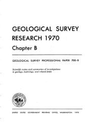
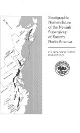
Analyst extension for ArcView. The final design<br />
produced four bird-survey stations spaced 250<br />
m apart; 10, 100 x 100 m amphibian <strong>and</strong> reptile<br />
plots; <strong>and</strong> 20, 50 x 50 m mammal plots along the<br />
focal-point transect line (Fig. 1.1). We sampled<br />
1 2 3 3 4 4<br />
Figure 1.1. Layout <strong>of</strong> 1-km focal-point transects showing layout <strong>of</strong> amphibian <strong>and</strong><br />
reptile plots (C), small-mammal trapping grids (D), <strong>and</strong> bird survey stations (E).