Wind field simulations at Askervein hill - WindSim
Wind field simulations at Askervein hill - WindSim
Wind field simulations at Askervein hill - WindSim

You also want an ePaper? Increase the reach of your titles
YUMPU automatically turns print PDFs into web optimized ePapers that Google loves.
∂<br />
( ρε )<br />
∂t<br />
p<br />
∂<br />
+<br />
∂x<br />
i<br />
⎛<br />
⎜ ρε<br />
p<br />
⎝<br />
∂U<br />
∂x<br />
i<br />
ρν<br />
T<br />
−<br />
C<br />
( ε )<br />
p<br />
∂ε<br />
p<br />
⎞<br />
⎟<br />
ρ<br />
=<br />
∂x<br />
i ⎠ k<br />
p<br />
2<br />
2<br />
( C p + C p ε − C ε )<br />
p1 k p2<br />
k p p3<br />
p<br />
∂<br />
( ρε )<br />
∂t<br />
t<br />
∂<br />
+<br />
∂x<br />
i<br />
⎛ ∂U<br />
⎜ ρε<br />
t<br />
⎝ ∂xi<br />
ρν<br />
T<br />
−<br />
C<br />
∂ε<br />
C<br />
t<br />
⎞<br />
⎟ = ρ<br />
⎠<br />
2<br />
2<br />
t1ε<br />
p<br />
+ Ct2ε<br />
tε<br />
p<br />
− Ct3ε<br />
t<br />
( ε<br />
t<br />
) ∂x<br />
⎟<br />
i<br />
kt<br />
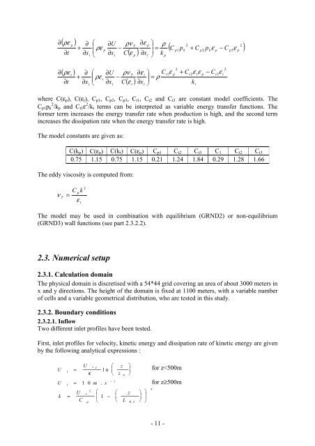
where C(ε p ), C(ε t ), C p1 , C p2 , C p3 , C t1 , C t2 and C t3 are constant model coefficients. The<br />
C p1 p k 2 /k p and C t1 ε 2 /k t terms can be interpreted as variable energy transfer functions. The<br />
former term increases the energy transfer r<strong>at</strong>e when production is high, and the second term<br />
increases the dissip<strong>at</strong>ion r<strong>at</strong>e when the energy transfer r<strong>at</strong>e is high.<br />
The model constants are given as:<br />
C(k p ) C(ε p ) C(k t ) C(ε p ) C p1 C t2 C t3 C 1 C t2 C t3<br />
0.75 1.15 0.75 1.15 0.21 1.24 1.84 0.29 1.28 1.66<br />
The eddy viscosity is computed from:<br />
ν<br />
T<br />
=<br />
C<br />
µ<br />
ε<br />
k<br />
t<br />
2<br />
The model may be used in combin<strong>at</strong>ion with equilibrium (GRND2) or non-equilibrium<br />
(GRND3) wall functions (see part 2.3.2.2).<br />
2.3. Numerical setup<br />
2.3.1. Calcul<strong>at</strong>ion domain<br />
The physical domain is discretised with a 54*44 grid covering an area of about 3000 meters in<br />
x and y directions. The height of the domain is fixed <strong>at</strong> 1100 meters, with a variable number<br />
of cells and a variable geometrical distribution, who are tested in this study.<br />
2.3.2. Boundary conditions<br />
2.3.2.1. Inflow<br />
Two different inlet profiles have been tested.<br />
First, inlet profiles for velocity, kinetic energy and dissip<strong>at</strong>ion r<strong>at</strong>e of kinetic energy are given<br />
by the following analytical expressions :<br />
U<br />
1<br />
=<br />
U<br />
κ<br />
* τ<br />
U = 1 0 m s<br />
k<br />
1<br />
⎛<br />
l n ⎜<br />
⎝<br />
z<br />
z<br />
0<br />
⎞<br />
⎟<br />
⎠<br />
for z