
You also want an ePaper? Increase the reach of your titles
YUMPU automatically turns print PDFs into web optimized ePapers that Google loves.
TOSHIBA Bar Code Printer<br />
B-<strong>SA4T</strong> <strong>Series</strong><br />
Key Operation Specification<br />
1st Edition : February 21, 2005<br />
2nd Edition : April 20, 2005<br />
3rd Edition : March 29, 2006<br />
4th Edition : June 30, 2006<br />
5th Edition : October 10, 2007<br />
6th Edition : February 14, 2008<br />
7th Edition : March 30, 2009<br />
8th Edition : May 6, 2010
TABLE OF CONTENTS<br />
Page<br />
1. SCOPE......................................................................................................................................... 1<br />
2. OUTLINE ..................................................................................................................................... 1<br />
3. OPERATION PANEL .................................................................................................................. 1<br />
4. KEY OPERATION FLOW............................................................................................................ 2<br />
5. ONLINE MODE............................................................................................................................ 3<br />
5.1 KEY FUNCTIONS .................................................................................................................. 3<br />
5.2 LED FUNCTIONS................................................................................................................... 3<br />
5.3 LCD FUNCTIONS .................................................................................................................. 3<br />
5.4 ONLINE MODE OPERATION EXAMPLE.............................................................................. 4<br />
5.5 THRESHOLD SETTING......................................................................................................... 5<br />
5.5.1 Outline of Threshold Setting ............................................................................................ 5<br />
5.5.2 Threshold Setting Operation Example............................................................................. 5<br />
5.6 RESET.................................................................................................................................... 7<br />
5.7 PARAMETER SETTING......................................................................................................... 8<br />
5.7.1 Parameter Setting Operation Example ............................................................................ 8<br />
5.7.2 Parameter Setting Items .................................................................................................. 13<br />
5.8 FINE ADJUSTMENT VALUE SETTING................................................................................. 16<br />
5.8.1 Fine Adjustment Value Setting Operation Example ........................................................ 16<br />
5.8.2 Fine Adjustment Value Setting Items............................................................................... 19<br />
5.9 DUMPING OF RECEIVE BUFFER ........................................................................................ 20<br />
5.9.1 Operation Example of Receive Buffer Dumping.............................................................. 20<br />
5.10 BASIC EXPANSION MODE................................................................................................... 23<br />
5.11 AUTOMATIC CALIBRATION SETTING................................................................................. 24<br />
5.11.1 Operation Example of Automatic Calibration Setting ...................................................... 24<br />
5.12 LAN ENABLE/DISABLE SETTING ........................................................................................ 27<br />
5.12.1 Operation Example of LAN Enable/Disable Setting ........................................................ 27<br />
5.13 REAL TIME CLOCK (RTC) SETTING.................................................................................... 29<br />
5.13.1 Operation Example of RTC Setting ................................................................................. 29<br />
5.14 BASIC SETTING .................................................................................................................... 32<br />
5.14.1 Operation Example of BASIC Setting .............................................................................. 32<br />
5.15 Z-MODE SETTING................................................................................................................. 35<br />
5.15.1 Operation Example of Z-Mode Setting ............................................................................ 35<br />
5.16 LCD MESSAGES AND LED INDICATIONS .......................................................................... 37<br />
5.17 LCD MESSAGES IN DIFFERENT LANGUAGES (UPPER LINE OF LCD) .......................... 40<br />
i
Page<br />
6. SYSTEM MODE........................................................................................................................... 42<br />
6.1 OUTLINE OF SYSTEM MODE .............................................................................................. 42<br />
6.2 SELF-TEST ............................................................................................................................ 44<br />
6.2.1 Self-test Operation Example ............................................................................................ 44<br />
6.2.2 Self-test Items .................................................................................................................. 48<br />
6.2.2.1 Details of Self-test Result....................................................................................... 53<br />
6.3 VARIOUS PARAMETERS SETTING..................................................................................... 64<br />
6.3.1 Various Parameters Setting Operation Example............................................................. 64<br />
6.3.2 Details of Various Parameter Setting............................................................................... 69<br />
6.4 FINE ADJUSTMENT VALUE SETTING................................................................................. 83<br />
6.4.1 Fine Adjustment Value Setting Operation Example ........................................................ 83<br />
6.4.2 Details of Fine Adjustment Value Setting ........................................................................ 85<br />
6.5 TEST PRINT........................................................................................................................... 93<br />
6.5.1 Test Print Operation Example.......................................................................................... 93<br />
6.5.2 Details of Test Print Setting ............................................................................................. 97<br />
6.5.3 Test Print Samples........................................................................................................... 101<br />
6.6 SENSOR DISPLAY/ADJUSTMENT....................................................................................... 105<br />
6.6.1 Sensor Display/Adjustment Operation Example.............................................................. 105<br />
6.6.2 Details of Sensor Adjustment Value Display ................................................................... 107<br />
6.7 RAM CLEAR........................................................................................................................... 108<br />
6.7.1 RAM Clear Operation Example........................................................................................ 108<br />
6.7.2 Details of RAM Clear ....................................................................................................... 110<br />
6.8 IP ADDRESS SETTING ......................................................................................................... 114<br />
6.8.1 IP Address Setting Operation Example ........................................................................... 114<br />
6.8.2 IP Address Setting Operation Flow.................................................................................. 121<br />
6.9 BASIC SETTING .................................................................................................................... 122<br />
6.9.1 BASIC Setting Operation Example .................................................................................. 122<br />
6.10 ADJUSTMENT MODE FOR FACTORY................................................................................. 125<br />
6.11 RFID SETTING....................................................................................................................... 127<br />
6.11.1 RFID Setting Operation Example..................................................................................... 127<br />
6.11.2 Details of RFID Setting .................................................................................................... 131<br />
6.12 Z-MODE SETTING................................................................................................................. 140<br />
6.12.1 Z-Mode Setting Operation Example ................................................................................ 140<br />
7. DOWNLOAD MODE.................................................................................................................... 143<br />
Copyright © 2005<br />
by TOSHIBA TEC CORPORATION<br />
All Rights Reserved<br />
570 Ohito,Izunokuni-shi,Shizuoka-ken,JAPAN<br />
ii
1. SCOPE<br />
This specification describes key operations of the B-<strong>SA4T</strong> <strong>Series</strong> general-purpose bar code printers<br />
(hereinafter referred to as “B-<strong>SA4T</strong>”) using the B-<strong>SA4T</strong> keys and the LCD display.<br />
2. OUTLINE<br />
The B-<strong>SA4T</strong> key operations are performed roughly in two modes: online mode and system mode. In<br />
online mode, where the B-<strong>SA4T</strong> is connected to a host device such as a personal computer, the key<br />
operations are performed mainly to pause or restart the B-<strong>SA4T</strong> and to display printer status messages<br />
and error messages on the LCD. In system mode, the key operations are performed mainly to conduct<br />
a self-test and to make various parameter settings. This specification describes the key operations in<br />
these two modes and in download mode.<br />
For explanation purposes, this specification uses English key names and LCD messages, although<br />
other languages are available for key names and LCD messages.<br />
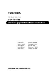
3. OPERATION PANEL<br />
O N L I N E<br />
B - S A 4 T - T V 1 . 2 A<br />
LCD (16 digits x 2 lines)<br />
ON LINE LED (Green)<br />
ERROR LED (Red)<br />
FEED Key<br />
RESTART key<br />
PAUSE key<br />
- 1 -
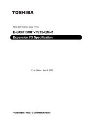
4. KEY OPERATION FLOW<br />
[Power OFF]<br />
Turn the power on.<br />
[Online]<br />
System mode<br />
[FEED] key<br />
[PAUSE] key<br />
While holding down the [FEED],<br />
[RESTART], and [PAUSE] keys,<br />
turn the power on.<br />
Online mode<br />
While holding down the [FEED] and [RESTART]<br />
keys, turn the power on.<br />
While holding down the [FEED] and [PAUSE] keys,<br />
turn the power on.<br />
[RESTART] key<br />
[RESTART] key<br />
[RESTART] key<br />
[RESTART] key<br />
[RESTART] key<br />
[RESTART] key<br />
[Self-test]<br />
[Parameter setting]<br />
[Feeds one label.]<br />
[Pause]<br />
[Fine adjustment value setting]<br />
[Test print]<br />
[FEED] key<br />
[FEED] key<br />
[FEED] key<br />
[FEED] key<br />
[Sensor display/adjustment]<br />
[FEED] key<br />
[RESTART] key<br />
Hold down the [PAUSE] key for a few seconds.<br />
Hold down the [RESTART] key<br />
for a few seconds.<br />
[Transmissive sensor threshold setting mode]<br />
[FEED] key<br />
[Reflective sensor threshold setting mode]<br />
[RESTART] key<br />
[RESTART] key<br />
[RESTART] key<br />
[RESTART] key<br />
[RESTART] key<br />
[RESTART] key<br />
[RESTART] key<br />
[RESTART] key<br />
[RESTART] key<br />
[RESTART] key<br />
[Reset]<br />
[FEED] key<br />
[Parameter setting]<br />
[FEED] key<br />
[Fine adjustment value setting]<br />
[FEED] key<br />
[Dump mode]<br />
[FEED] key<br />
[BASIC expansion mode]<br />
[FEED] key<br />
[Automatic calibration mode]<br />
[FEED] key<br />
[LAN Enable/Disable]<br />
[FEED] key<br />
[RTC setting]<br />
[BASIC setting]<br />
[Z-MODE]<br />
[FEED] key<br />
[FEED] key<br />
[FEED] key<br />
* Supported from C1.9A<br />
[RAM clear]<br />
[RESTART] key [FEED] key<br />
[IP address setting]<br />
[RESTART] key [FEED] key<br />
[BASIC setting]<br />
[RESTART] key [FEED] key<br />
[FOR FACTORY]<br />
[RESTART] key [FEED] key<br />
[RFID Setting]<br />
[RESTART] key [FEED] key<br />
[Z-MODE]<br />
* Supported from C1.9A<br />
[FEED] key<br />
[Self-test]<br />
Download mode<br />
[RESTART] key [FEED] key<br />
[Fine adjustment value setting]<br />
[RESTART] key [FEED] key<br />
[Test print]<br />
[FEED] key<br />
[RESTART] key<br />
[Parameter setting]<br />
[RESTART] key [FEED] key<br />
[RESTART] key [FEED] key<br />
[Z-MODE]<br />
- 2 -
5. ONLINE MODE<br />
5.1 KEY FUNCTIONS<br />
[FEED] key:<br />
(1) Feeds or ejects one label. This key is also used to adjust a label to a proper<br />
position. When the label is not properly positioned, feed one or two blank<br />
labels using this key before printing so that the printer can start printing at the<br />
proper position.<br />
(2) Prints data in the image buffer on one label according to the system mode<br />
setting.<br />
NOTE:<br />
When printing is initiated by the [FEED] key, a Clear command or a<br />
drawing command should not be sent during printing, otherwise the<br />
resulting printout will not be satisfactory showing an incorrect layout.<br />
The same may happen if the [FEED] key is pressed to start printing<br />
while data is being drawn in the image buffer.<br />
* For handling of labels having the label pitch of less than 22 mm in cut issue<br />
mode, refer to the section, “6.4 FINE ADJUSTMENT VALUE SETTING”.<br />
[RESTART] key:<br />
[PAUSE] key:<br />
(1) Resumes printing when the printer is in a pause state or an error state.<br />
(2) Restores the same state as when the power is turned off and on again.<br />
(3) Programs various parameters.<br />
(1) Stops printing temporarily.<br />
(2) Programs threshold values.<br />
5.2 LED FUNCTIONS<br />
[ON LINE] LED:<br />
[ERROR] LED:<br />
Indicates that the printer is ready for communication.<br />
Indicates that the printer is in an error state.<br />
5.3 LCD FUNCTIONS<br />
The LCD displays printer status messages.<br />
LCD Size: 16 digits × 2 lines<br />
- 3 -
5.4 ONLINE MODE OPERATION EXAMPLE<br />
Power ON<br />
O N<br />
L I N E<br />
B - S A 4 T - T V 1 . 2 A<br />
* This message is displayed while the printer is<br />
idling or printing normally.<br />
An error occurs.<br />
N O P A P E R 1 2 5<br />
B - S A 4 T - T V 1 . 2 A<br />
* An error message is displayed when an error<br />
occurs during printing, then the printing stops.<br />
(The number of remaining labels to be printed is<br />
displayed at the right of the LCD.)<br />
[RESTART]<br />
O N L I N E<br />
B - S A 4 T - T V 1 . 2 A<br />
Load label paper and press the [RESTART] key.<br />
* This message is displayed and the printing<br />
resumes.<br />
[PAUSE]<br />
P A U S E 5 2<br />
B - S A 4 T - T V 1 . 2 A<br />
Press the [PAUSE] key.<br />
* When the [PAUSE] key is pressed during printing,<br />
this message is displayed and the printing stops.<br />
(The number of remaining labels to be printed is<br />
displayed at the right of the LCD.)<br />
[RESTART]<br />
O N L I N E<br />
B - S A 4 T - T V 1 . 2 A<br />
Press the [RESTART] key.<br />
* This message is displayed and the printing<br />
resumes.<br />
NOTE: [Number of remaining labels to be printed] = [Total number of labels to be printed] -<br />
[Number of labels already printed before an error occurred or the printer stopped temporarily]<br />
- 4 -
5.5 THRESHOLD SETTING<br />
5.5.1 Outline of Threshold Setting<br />
To always start printing at a proper position, the printer automatically corrects a print start<br />
position using a transmissive or reflective sensor. However, the printer sometimes fails to<br />
correct the print start position properly.<br />
For label papers, a transmissive sensor is used to detect a gap between labels. When<br />
preprinted labels are used, transmissivity may vary due to inks used, and the printer may not be<br />
able to correct the print start position properly. For tag papers with black marks printed on the<br />
back side, a reflective sensor is used to detect the black marks. When reflectivity of the area<br />
other than the black marks varies, the printer may not be able to correct the print start position<br />
properly.<br />
In these cases, the printer can correct the print start position properly by using a transmissive<br />
sensor threshold value/reflective sensor threshold value manually determined and stored in a<br />
non-volatile memory (EEPROM) by performing the key operation explained in the subsequent<br />
section, “Threshold Setting Operation Example” and by setting the type of sensor for Issue and<br />
Feed commands to “3: Transmissive Sensor (when using a manual threshold value)” or “4:<br />
Reflective Sensor (when using a manual threshold value)”.<br />
5.5.2 Threshold Setting Operation Example<br />
Power ON<br />
O N L I N E (1) Idling<br />
B - S A 4 T - T V 1 . 2 A (2) Load a preprinted label paper.<br />
(No particular positioning is required.)<br />
P A U S E<br />
[PAUSE]<br />
B - S A 4 T - T V 1 . 2 A<br />
(3) Press the [PAUSE] key.<br />
(4) The printer enters a pause state.<br />
[PAUSE]<br />
T R A N S M I S S I V E<br />
B - S A 4 T - T V 1 . 2 A<br />
[FEED]<br />
R E F L E C T I V E<br />
B - S A 4 T - T V 1 . 2 A<br />
(5) Hold down the [PAUSE] key for 3 seconds or<br />
more while the printer is in a pause state.<br />
(6) A sensor, for which a manual threshold value<br />
is to be determined, is displayed.<br />
A message to select the transmissive sensor is<br />
displayed.<br />
(7) Press the [FEED] key.<br />
(8) A message to select the reflective sensor is<br />
displayed.<br />
[FEED]<br />
(9) Press the [FEED] key.<br />
- 5 -
T R A N S M I S S I V E<br />
B - S A 4 T - T V 1 . 2 A<br />
(10) A message to select the transmissive sensor is<br />
displayed.<br />
[PAUSE]<br />
T R A N S M I S S I V E<br />
B - S A 4 T - T V 1 . 2 A<br />
(11) Continue holding down the [PAUSE] key.<br />
(12) Release the [PAUSE] key when 1.5 or more<br />
labels are fed to stop printing. (The threshold<br />
setting for the selected sensor (transmissive<br />
sensor in this example) is completed.<br />
P A U S E<br />
(13) The printer enters a pause state.<br />
B - S A 4 T - T V 1 . 2 A<br />
[RESTART]<br />
(14) Press the [RESTART] key.<br />
O N L I N E (15) Idling<br />
B - S A 4 T - T V 1 . 2 A<br />
Command<br />
O N<br />
L I N E<br />
B - S A 4 T - T V 1 . 2 A<br />
(16) The printer starts printing according to a<br />
command sent from a PC.<br />
<br />
(1) When the [PAUSE] key is pressed and released within 3 seconds while the printer is<br />
paused, no action is taken.<br />
(2) To obtain an accurate threshold value, 1.5 or more labels should be fed. (If less than 1.5<br />
labels are fed, the threshold value may not be accurate enough to start printing at a proper<br />
print start position. If the print start position is not correct, the threshold setting operation<br />
should be performed again.)<br />
(3) When the [PAUSE] key is held down for 3 seconds or more with the head lifted, no action is<br />
taken.<br />
(4) While the printer is feeding labels to determine a threshold value, no errors, including paper<br />
end error and cutter error, are detected.<br />
(5) If the printer still does not start printing at the proper print start position after the threshold<br />
setting operation is performed, it can be suspected that a sensor adjustment is not proper.<br />
In this case, readjust the sensor in system mode, then perform the threshold setting<br />
operation again.<br />
When the backing paper of a label paper is too thick, the transmissive sensor should be<br />
readjusted.<br />
In addition, make sure that the type of sensor for Issue and Feed commands is set to “3:<br />
Transmissive sensor (when using a manual threshold value)” or “4: Reflective sensor (when<br />
using a manual threshold value)”.<br />
- 6 -
5.6 RESET<br />
Power ON<br />
O N L I N E (1) Idling or printing normally<br />
B - S A 4 T - T V 1 . 2 A<br />
[PAUSE]<br />
P A U S E 5 2<br />
B - S A 4 T - T V 1 . 2 A<br />
(2) Press the [PAUSE] key.<br />
* If the [PAUSE] key is pressed during printing, this<br />
message is displayed and printing stops.<br />
[RESTART]<br />
(3) Hold down the [RESTART] key for 3 seconds<br />
or more while the printer is in a pause state.<br />
< 1 > R E S E T (4) The reset menu is displayed.<br />
[PAUSE]<br />
O N L I N E<br />
B - S A 4 T - T V 1 . 2 A<br />
(5) Press the [PAUSE] key.<br />
(6) The printer returns to the same state as when<br />
the power is turned off and on again.<br />
<br />
(1) When pressing the [RESTART] key can clear an error (a recoverable error by the<br />
[RESTART] key), the printer enters reset mode and displays a reset menu when the<br />
[RESTART] key is pressed for 3 seconds or more.<br />
(2) When the [RESTART] key is pressed and released within 3 seconds in an error state or a<br />
pause state, the printer resumes printing. (The reset menu is not displayed on the LCD.)<br />
When the [RESTART] key is pressed in a communication error state or a command error<br />
state, the printer returns to the same state as when the power is turned off and on again,<br />
whether or not the [RESTART] key is held down for 3 seconds or more.<br />
- 7 -
5.7 PARAMETER SETTING<br />
5.7.1 Parameter Setting Operation Example<br />
Power ON<br />
O N L I N E (1) Idling or printing normally<br />
B - S A 4 T - T V 1 . 2 A<br />
[PAUSE]<br />
(2) Press the [PAUSE] key.<br />
P A U S E 5 2 (3) “PAUSE” is displayed.<br />
B - S A 4 T - T V 1 . 2 A<br />
[RESTART]<br />
(4) Hold down the [RESTART] key for 3 seconds<br />
or more while the printer is a pause state.<br />
< 1 > R E S E T (5) The reset menu is displayed.<br />
[FEED]<br />
(6) Press the [FEED] key.<br />
< 2 > P A R A M E T E R S E T (7) System mode menu display<br />
(Parameter setting)<br />
[PAUSE]<br />
< 2 > P A R A M E T E R S E T<br />
F O N T C O D E P C - 8 5 0<br />
(8) Press the [PAUSE] key.<br />
(9) Character code setting:<br />
Select a character code using the [FEED] and<br />
[RESTART] keys.<br />
[PAUSE]<br />
< 2 > P A R A M E T E R S E T<br />
Z E R O F O N T 0<br />
(10) Press the [PAUSE] key.<br />
(11) Font 0 setting:<br />
Select a style of zero (0) using the [FEED] and<br />
[RESTART] keys.<br />
[PAUSE]<br />
< 2 > P A R A M E T E R S E T<br />
S P E E D<br />
9 6 0 0 b p s<br />
(12) Press the [PAUSE] key.<br />
(13) RS232C communication speed setting:<br />
Select a communication speed using the<br />
[FEED] and [RESTART] keys.<br />
[PAUSE]<br />
< 2 > P A R A M E T E R S E T<br />
D A T A L E N G . 8 b i t s<br />
(14) Press the [PAUSE] key.<br />
(15) RS232C data length setting:<br />
Select a data length using the [FEED] and<br />
[RESTART] keys.<br />
[PAUSE]<br />
(16) Press the [PAUSE] key.<br />
- 8 -
2 > P A R A M E T E R S E T<br />
S T O P B I T 1 b i t<br />
(17) RS232C stop bit length setting:<br />
Select a stop bit length using the [FEED] and<br />
[RESTART] keys.<br />
[PAUSE]<br />
< 2 > P A R A M E T E R S E T<br />
P A R I T Y<br />
E V E N<br />
(18) Press the [PAUSE] key.<br />
(19) RS232C parity setting:<br />
Select a parity value using the [FEED] and<br />
[RESTART] keys.<br />
[PAUSE]<br />
< 2 > P A R A M E T E R S E T<br />
X O N + R E A D Y A U T O<br />
(20) Press the [PAUSE] key.<br />
(21) RS232C flow control method setting:<br />
Select a flow control method using the [FEED]<br />
and [RESTART] keys.<br />
[PAUSE]<br />
< 2 > P A R A M E T E R S E T<br />
L C D<br />
E N G L I S H<br />
(22) Press the [PAUSE] key.<br />
(23) Setting of language for LCD messages:<br />
Select a language for LCD messages using the<br />
[FEED] and [RESTART] keys.<br />
[PAUSE]<br />
< 2 > P A R A M E T E R S E T<br />
F O R W A R D W A I T O F F<br />
[PAUSE]<br />
< 2 > P A R A M E T E R S E T<br />
C O D E E S C , L F , N U L<br />
(24) Press the [PAUSE] key.<br />
(25) Setting of forward feed standby after an issue:<br />
Enable/disable the forward feed standby<br />
function using the [FEED] and [RESTART]<br />
keys.<br />
(26) Press the [PAUSE] key.<br />
(27) Control code setting:<br />
Select a control code using the [FEED] and<br />
[RESTART] keys.<br />
[PAUSE]<br />
< 2 > P A R A M E T E R S E T<br />
P E E L O F F S T S O F F<br />
(28) Press the [PAUSE] key.<br />
(29) Strip wait status setting:<br />
Enable/disable the strip wait status function<br />
using the [FEED] and [RESTART] keys.<br />
[PAUSE]<br />
< 2 > P A R A M E T E R S E T<br />
F E E D K E Y F E E D<br />
(30) Press the [PAUSE] key.<br />
(31) [FEED] key function setting:<br />
Select a function of the [FEED] key using the<br />
[FEED] and [RESTART] keys.<br />
[PAUSE]<br />
< 2 > P A R A M E T E R S E T<br />
K A N J I C O D E T Y P E 1<br />
(32) Press the [PAUSE] key.<br />
(33) Kanji code setting:<br />
Select a Kanji code using the [FEED] and<br />
[RESTART] keys.<br />
[PAUSE]<br />
(34) Press the [PAUSE] key.<br />
- 9 -
2 > P A R A M E T E R S E T<br />
E U R O C O D E B 0<br />
(35) Euro code setting:<br />
Select a Euro code using the [FEED] and<br />
[RESTART] keys.<br />
[PAUSE]<br />
< 2 > P A R A M E T E R S E T<br />
A U T O H D C H K O F F<br />
(36) Press the [PAUSE] key.<br />
(37) Automatic head broken dots check setting:<br />
Enable/disable the automatic head broken dots<br />
check using the [FEED] and [RESTART] keys.<br />
[PAUSE]<br />
< 2 > P A R A M E T E R S E T<br />
A C K / B U S Y T Y P E 1<br />
(38) Press the [PAUSE] key.<br />
(39) Centronics ACK/BUSY timing setting:<br />
Select an ACK/BUSY timing using the [FEED]<br />
and [RESTART] keys.<br />
[PAUSE]<br />
< 2 > P A R A M E T E R S E T<br />
W E B P R I N T E R O F F<br />
(40) Press the [PAUSE] key.<br />
(41) Web printer function setting:<br />
Enable/disable the web printer function using<br />
the [FEED] and [RESTART] keys.<br />
[PAUSE]<br />
< 2 > P A R A M E T E R S E T<br />
I N P U T P R I M E O N<br />
[PAUSE]<br />
< 2 > P A R A M E T E R S E T<br />
R B N N E A R E N D 7 0 m<br />
[PAUSE]<br />
< 2 > P A R A M E T E R S E T<br />
E X . I / O T Y P E 1<br />
(42) Press the [PAUSE] key.<br />
(43) Setting of reset process when the nInit signal is<br />
ON:<br />
Enable/disable the reset process function<br />
using the [FEED] and [RESTART] keys.<br />
(44) Press the [PAUSE] key.<br />
(45) Ribbon near end detection setting:<br />
Select a remaining ribbon length to be detected<br />
as a ribbon near end state using the [FEED]<br />
and [RESTART] keys.<br />
(46) Press the [PAUSE] key.<br />
(47) Expansion I/O operation mode setting:<br />
Select an expansion I/O operation mode using<br />
the [FEED] and [RESTART] keys.<br />
[PAUSE]<br />
< 2 > P A R A M E T E R S E T<br />
P L U G & P L A Y O F F<br />
[PAUSE]<br />
< 2 > P A R A M E T E R S E T<br />
L B L / R B N E N D T Y P 1<br />
(48) Press the [PAUSE] key.<br />
(49) Plug-and-play operation setting:<br />
Enable/disable the plug-and-play operation<br />
function using the [FEED] and [RESTART]<br />
keys.<br />
(50) Press the [PAUSE] key.<br />
(51) Label end/ribbon error process setting:<br />
Select a label end/ribbon error process using<br />
the [FEED] and [RESTART] keys.<br />
[PAUSE]<br />
(52) Press the [PAUSE] key.<br />
- 10 -
2 > P A R A M E T E R S E T<br />
P R E P E E L O F F O F F<br />
(53) Pre-strip function setting:<br />
Enable/disable the pre-strip function using the<br />
[FEED] and [RESTART] keys.<br />
[PAUSE]<br />
< 2 > P A R A M E T E R S E T<br />
B A C K S P E E D S T D<br />
(54) Press the [PAUSE] key.<br />
(55) Reverse feed speed setting:<br />
Select a reverse feed speed using the [FEED]<br />
and [RESTART] keys.<br />
[PAUSE]<br />
< 2 > P A R A M E T E R S E T<br />
M A X I C O D E T Y P E 1<br />
(56) Press the [PAUSE] key.<br />
(57) MaxiCode specification setting:<br />
Select a type of MaxiCode specification using<br />
the [FEED] and [RESTART] keys.<br />
[PAUSE]<br />
< 2 > P A R A M E T E R S E T<br />
K B I / F O F F<br />
(58) Press the [PAUSE] key.<br />
(59) Keyboard I/F setting:<br />
Enable/disable the keyboard I/F using the<br />
[FEED] and [RESTART] keys.<br />
[PAUSE]<br />
< 2 > P A R A M E T E R S E T<br />
P E E L O F F T R Q R 0<br />
(60) Press the [PAUSE] key.<br />
(61) Strip motor torque setting:<br />
Select a strip motor torque using the [FEED]<br />
and [RESTART] keys.<br />
[PAUSE]<br />
< 2 > P A R A M E T E R S E T<br />
T O N E T A B L E T Y P E 1<br />
(62) Press the [PAUSE] key.<br />
(63) Print head applied current table setting:<br />
Select the type of table using the [FEED] or<br />
[RESTART] key.<br />
[PAUSE]<br />
< 2 > P A R A M E T E R S E T<br />
C U T M O D E T Y P E 1<br />
(64) Press the [PAUSE] key.<br />
(65) High speed cut issue:<br />
Select a cut issue type using the [FEED] and<br />
[RESTART] keys.<br />
[PAUSE]<br />
< 2 > P A R A M E T E R S E T<br />
M U L T I L A B E L O F F<br />
(66) Press the [PAUSE] key.<br />
(67) Multiple-label set issue:<br />
Enable or disable the function using the<br />
[FEED] or [RESTART] key.<br />
[PAUSE]<br />
< 2 > P A R A M E T E R S E T<br />
P A S S W O R D O F F - - - -<br />
(68) Press the [PAUSE] key.<br />
(69) System mode password operation setting:<br />
Set the system mode password operation<br />
setting using the [FEED] or [RESTART] key.<br />
[PAUSE]<br />
(70) Press the [PAUSE] key.<br />
- 11 -
2 > P A R A M E T E R S E T (71) The parameter setting menu is displayed.<br />
- 12 -
5.7.2 Parameter Setting Items<br />
For details, refer to the section, “6.3 VARIOUS PARAMETER SETTING”.<br />
(1) Character code (FONT CODE)<br />
• PC-850 • PC-852<br />
• PC-857 • PC-8<br />
• PC-851 • PC-855<br />
• PC-1250 • PC-1251<br />
• PC-1252 • PC-1253<br />
• PC-1254 • PC-1257<br />
• LATIN9 • Arabic<br />
• PC-855 • PC-866<br />
• UTF-8<br />
(2) Font 0 (ZERO FONT)<br />
• 0 (without slash)<br />
• 0 (with slash)<br />
(3) RS-232C communication speed (SPEED)<br />
• 2400 bps<br />
• 4800 bps<br />
• 9600 bps<br />
• 19200 bps<br />
• 38400 bps<br />
• 115200 bps<br />
(4) RS-232C data length (DATA LENG.)<br />
• 7 bits<br />
• 8 bits<br />
(5) RS-232C stop bit length (STOP BIT)<br />
• 1 bit<br />
• 2 bits<br />
(6) RS-232C parity (PARITY)<br />
• NONE<br />
• EVEN<br />
• ODD<br />
(7) RS-232C flow control method (XON+READY)<br />
• XON/XOFF protocol<br />
• READY/BUSY (DTR) protocol<br />
• XON/XOFF + READY/BUSY (DTR) protocol<br />
• XON/XOFF protocol<br />
• RTS protocol<br />
(An XON is not output when the power is<br />
on and an XOFF is not output when the<br />
power is off.)<br />
(An XON is not output when the power is<br />
on and an XOFF is not output when the<br />
power is off.)<br />
(An XON is output when the power is on<br />
and an XOFF is output when the power is<br />
off)<br />
(An XON is output when the power is on<br />
and an XOFF is output when the power is<br />
off)<br />
(An XON is not output when the power is<br />
on and an XOFF is not output when the<br />
power is off)<br />
- 13 -
(8) Language for LCD messages (LCD)<br />
• ENGLISH<br />
• GERMAN<br />
• FRENCH<br />
• DUTCH<br />
• SPANISH<br />
• JAPANESE<br />
• ITALIAN<br />
NOTE: Japanese character codes are slightly different from those of other languages.<br />
For details, refer to the External Equipment Interface Specification (TAA-2165).<br />
(9) Forward feed standby after an issue (FORWARD WAIT)<br />
• ON: The forward feed standby after an issue function is enabled.<br />
• POSITION: A fine adjustment value for a stop position after a forward feed is set.<br />
• OFF: The forward feed standby after an issue function is disabled.<br />
NOTE:<br />
When the forward feed standby after an issue parameter is set to ON, the printer<br />
enters a pause state after a label is issued. The printer automatically starts to<br />
feed the label approximately 17 mm forward when a time of 1 second or more<br />
passes in the pause state, then stops.<br />
(10) Control code (CODE)<br />
• Automatic selection (ESC, LF, NUL/{ | })<br />
• Manual selection (ESC, LF, NUL method)<br />
• Manual selection ({ | } method)<br />
• Any code set<br />
• Manual selection ( | ) method) Note: Only for the Japan model.<br />
(11) Strip wait status (PEEL OFF STS)<br />
• ON: The strip wait status function is enabled.<br />
• OFF: The strip wait status function is disabled.<br />
(12) [FEED] key function (FEED KEY)<br />
• FEED: Feeds one label.<br />
• PRINT: Prints data in the image buffer on one label.<br />
(13) Kanji code (KANJI CODE)<br />
• TYPE1 (For Windows codes)<br />
• TYPE2 (For original codes)<br />
(14) Euro code (EURO CODE)<br />
• 20H to FFH<br />
(15) Automatic head broken dots check (AUTO HD CHK)<br />
• ON: A head broken dots check is automatically performed when the power is turned<br />
on.<br />
• OFF: A head broken dots check is not automatically performed when the power is<br />
turned on.<br />
(16) Centronics ACK/BUSY timing (ACK/BUSY)<br />
• TYPE1 BUSY goes low at the same time as when ACK goes high.<br />
• TYPE2 BUSY goes low at the same time as when ACK goes low.<br />
(17) Web printer function (WEB PRINTER)<br />
• ON: The web printer function is enabled.<br />
• OFF: The web printer function is disabled.<br />
(18) Reset process when the nInit signal is ON (INPUT PRIME)<br />
• ON: The reset process is performed.<br />
• OFF: The reset process is not performed.<br />
- 14 -
(19) Ribbon near end detection (RBN NEAR END)<br />
• OFF: A ribbon near end state is not detected.<br />
• 30 m: A ribbon near end state is detected when the remaining ribbon length is<br />
approximately 30 m.<br />
• 70 m: A ribbon near end state is detected when the remaining ribbon length is<br />
approximately 70 m.<br />
(20) Expansion I/O operation mode (EX. I/O)<br />
• TYPE1: Standard mode<br />
• TYPE2: In-line mode<br />
(21) Plug-and-play operation (PLUG & PLAY)<br />
• ON: A plug-and-play operation is performed.<br />
• OFF: A plug-and-play operation is performed.<br />
(22) Label end/ribbon error process (LBL/RBN END)<br />
• TYPE1: When a label end or ribbon error state is detected, the printer stops even if it is<br />
printing.<br />
• TYPE2: When a label end or ribbon error state is detected, the printer prints the current<br />
label as far as possible, then stops.<br />
(23) Pre-strip process (PRE PEEL OFF)<br />
• OFF: A pre-strip operation is not performed.<br />
• ON: A pre-strip operation is performed.<br />
NOTE: When the pre-strip operation parameter is set to ON, a 6-mm forward feed is<br />
performed, then a 6-mm reverse feed before printing on the label starts. The<br />
amount of feed can be finely adjusted.<br />
(24) Reverse feed speed (BACK SPEED)<br />
• STD: 3 ips<br />
• LOW: 2 ips<br />
(25) MaxiCode specification (MAXI CODE)<br />
• TYPE1: Compatible with a current version<br />
• TYPE2: Special specification<br />
(26) Keyboard I/F (KB I/F)<br />
• OFF: (Disabled)<br />
• KB60(1): KB-60 Old version<br />
• KB60(2): KB-60 Current version<br />
• KB80: KB-80<br />
(27) Strip motor torque (PEEL OFF TRQ)<br />
• R0: Low<br />
• R1: ↑<br />
• R2: ↓<br />
• R3: High<br />
(28) Print head applied current table setting (TONE TABLE)<br />
• TYPE1: Standard table<br />
• TYPE2: Additional table 1<br />
(29) High speed cut issue (CUT MODE)<br />
• TYPE1: Normal cut issue<br />
• TYPE2: High speed cut issue<br />
(30) Multiple-label set issue (MULTI LABEL)<br />
• OFF: Disabled (Normal operation)<br />
• ON: Enabled (Multiple-label set issue)<br />
(31) System mode password setting (PASSWORD)<br />
• OFF: Password is not asked to enter the system mode.<br />
• ON: Password is asked to enter the system mode.<br />
- 15 -
5.8 FINE ADJUSTMENT VALUE SETTING<br />
5.8.1 Fine Adjustment Value Setting Operation Example<br />
Power ON<br />
O N L I N E (1) Idling<br />
B - S A 4 T - T V 1 . 2 A<br />
P A U S E<br />
[PAUSE]<br />
B - S A 4 T - T V 1 . 2 A<br />
(2) Press the [PAUSE] key.<br />
(3) “PAUSE” is displayed.<br />
[RESTART]<br />
(4) Hold down the [RESTART] key for 3 seconds<br />
or more while the printer is in a pause state.<br />
< 1 > R E S E T (5) The reset menu is displayed.<br />
[FEED]<br />
(6) Press the [FEED] key.<br />
< 2 > P A R A M E T E R S E T (7) System mode menu display<br />
(Parameter setting)<br />
[FEED]<br />
(8) Press the [FEED] key.<br />
< 3 > A D J U S T S E T (9) System mode menu display<br />
(Fine adjustment value setting)<br />
[PAUSE]<br />
< 3 > A D J U S T S E T<br />
F E E D A D J . + 1 0 . 0 m m<br />
(10) Press the [PAUSE] key.<br />
(11) Feed amount fine adjustment:<br />
Set a fine adjustment value using the [FEED]<br />
and [RESTART] keys.<br />
[PAUSE]<br />
< 3 > A D J U S T S E T<br />
C U T A D J . + 5 . 0 m m<br />
(12) Press the [PAUSE] key.<br />
(13) Cut (strip) position fine adjustment:<br />
Set a fine adjustment value using the [FEED]<br />
and [RESTART] keys.<br />
[PAUSE]<br />
< 3 > A D J U S T S E T<br />
B A C K A D J . - 3 . 0 m m<br />
(14) Press the [PAUSE] key.<br />
(15) Back feed amount fine adjustment:<br />
Set a fine adjustment value using the [FEED]<br />
and [RESTART] keys.<br />
[PAUSE]<br />
(16) Press the [PAUSE] key.<br />
- 16 -
3 > A D J U S T S E T<br />
X A D J U S T + 5 0 . 0 m m<br />
(17) X-coordinate fine adjustment:<br />
Set a fine adjustment value using the [FEED]<br />
and [RESTART] keys.<br />
[PAUSE]<br />
< 3 > A D J U S T S E T<br />
T O N E A D J . < T > + 3<br />
[PAUSE]<br />
< 3 > A D J U S T S E T<br />
T O N E A D J . < D > - 2<br />
[PAUSE]<br />
< 3 > A D J U S T S E T<br />
R B N A D J < F W > - 1 0<br />
[PAUSE]<br />
< 3 > A D J U S T S E T<br />
R B N A D J < B K > - 5<br />
[PAUSE]<br />
< 3 > A D J U S T S E T<br />
T H R E S H O L D < R > 1 . 0 V<br />
[PAUSE]<br />
< 3 > A D J U S T S E T<br />
T H R E S H O L D < T > 1 . 4 V<br />
[PAUSE]<br />
(18) Press the [PAUSE] key.<br />
(19) Print tone fine adjustment<br />
(Thermal transfer print mode):<br />
Set a fine adjustment value using the [FEED]<br />
and [RESTART] keys.<br />
(20) Press the [PAUSE] key.<br />
(21) Print tone fine adjustment<br />
(Direct thermal print mode):<br />
Set a fine adjustment value using the [FEED]<br />
and [RESTART] keys.<br />
(22) Press the [PAUSE] key.<br />
(23) Ribbon motor drive voltage fine adjustment<br />
(Take-up):<br />
Set a fine adjustment value using the [FEED]<br />
and [RESTART] keys.<br />
(24) Press the [PAUSE] key.<br />
(25) Ribbon motor drive voltage fine adjustment<br />
(Feed):<br />
Set a fine adjustment value using the [FEED]<br />
and [RESTART] keys.<br />
(26) Press the [PAUSE] key.<br />
(27) Reflective sensor manual threshold fine<br />
adjustment:<br />
Set a fine adjustment value using the [FEED]<br />
and [RESTART] keys.<br />
(28) Press the [PAUSE] key.<br />
(29) Transmissive sensor manual threshold fine<br />
adjustment:<br />
Set a fine adjustment value using the [FEED]<br />
and [RESTART] keys.<br />
(30) Press the [PAUSE] key.<br />
< 3 > A D J U S T S E T (31) The find adjustment value setting menu is<br />
displayed.<br />
[RESTART]<br />
(32) Press the [RESTART] key.<br />
< 2 > P A R A M E T E R S E T (33) The parameter setting menu is displayed.<br />
[RESTART]<br />
(34) Press the [RESTART] key.<br />
- 17 -
1 > R E S E T (35) The reset menu is displayed.<br />
[PAUSE]<br />
O N L I N E<br />
B - S A 4 T - T V 1 . 2 A<br />
(36) Press the [PAUSE] key.<br />
(37) The printer returns to the same state as when<br />
the power is turned off and on again.<br />
- 18 -
5.8.2 Fine Adjustment Value Setting Items<br />
For details, refer to the section, “6.4 VARIOUS FINE ADJUSTMENT VALUE SETTING”.<br />
(1) Feed fine adjustment (FEED ADJ.)<br />
-50.0 mm to +50.0 mm (in 0.1 mm units)<br />
(2) Cut (strip) position fine adjustment (CUT ADJ.)<br />
-50.0 mm to +50.0 mm (in 0.1 mm units)<br />
(3) Back feed fine adjustment (BACK ADJ.)<br />
-9.9 mm to +9.9 mm (in 0.1 mm units)<br />
(4) X-coordinate fine adjustment (X ADJUST)<br />
-99.9 mm to +99.9 mm (in 0.1 mm units)<br />
(5) Print density fine adjustment (Thermal transfer print mode) (TONE ADJ.)<br />
-10 step to +10 step (in units of 1 step)<br />
(6) Print density fine adjustment (Direct thermal print mode) (TONE ADJ.)<br />
-10 step to +10 step (in units of 1 step)<br />
(7) Ribbon motor drive voltage fine adjustment (Take-up) (RBN ADJ )<br />
-15 step to +2 step (in units of 1 step)<br />
(8) Ribbon motor drive voltage fine adjustment (Feed) (RBN ADJ )<br />
-15 step to +10 step (in units of 1 step)<br />
(9) Reflective sensor manual threshold fine adjustment (THRESHOLD )<br />
0.0 V to 4.0 V<br />
(10) Transmissive sensor manual threshold fine adjustment (THRESHOLD )<br />
0.0 V to 4.0 V<br />
- 19 -
5.9 DUMPING OF RECEIVE BUFFER<br />
5.9.1 Operation Example of Receive Buffer Dumping<br />
Power ON<br />
O N L I N E (1) Idling<br />
B - S A 4 T - T V 1 . 2 A<br />
P A U S E<br />
[PAUSE]<br />
B - S A 4 T - T V 1 . 2 A<br />
(2) Press the [PAUSE] key.<br />
(3) “PAUSE” is displayed.<br />
[RESTART]<br />
(4) Hold down the [RESTART] key for 3 seconds<br />
or more while the printer is in a pause state.<br />
< 1 > R E S E T (5) The reset menu is displayed.<br />
[FEED]<br />
(6) Press the [FEED] key.<br />
< 2 > P A R A M E T E R S E T (7) System mode menu display<br />
(Parameter setting)<br />
[FEED]<br />
(8) Press the [FEED] key.<br />
< 3 > A D J U S T S E T (9) System mode menu display<br />
(Fine adjustment value setting)<br />
[FEED]<br />
(10) Press the [FEED] key.<br />
< 4 > D U M P M O D E (11) The receive buffer dumping menu is displayed.<br />
[PAUSE]<br />
< 4 > D U M P M O D E<br />
B U F F E R R S - 2 3 2 C<br />
(12) Press the [PAUSE] key.<br />
(13) Setting of receive buffer to be dumped:<br />
Select a receive buffer to be dumped using the<br />
[FEED] and [RESTART] keys<br />
[PAUSE]<br />
< 4 > D U M P M O D E<br />
P R I N T O N D E M A N D<br />
(14) Press the [PAUSE] key.<br />
(15) Print method setting:<br />
Select a print method using the [FEED] and<br />
[RESTART] keys.<br />
[PAUSE]<br />
(16) Press the [PAUSE] key.<br />
- 20 -
4 > D U M P M O D E<br />
N O W P R I N T I N G . . .<br />
(17) Start of printing receive buffer data<br />
(18) 166 lines of data are printed.<br />
< 4 > D U M P M O D E<br />
P R I N T O N D E M A N D<br />
(19) Print method setting:<br />
Select a print method using the [FEED] and<br />
[RESTART] keys.<br />
[RESTART]<br />
< 4 > D U M P M O D E<br />
P R I N T A L L<br />
(20) Press the [RESTART] key.<br />
(21) Print method setting:<br />
Select a print method using the [FEED] and<br />
[RESTART] keys.<br />
[PAUSE]<br />
< 4 > D U M P M O D E<br />
N O W P R I N T I N G . . .<br />
(22) Press the [PAUSE] key.<br />
(23) Start of printing the remaining receive buffer<br />
data<br />
(24) All of the remaining data is printed.<br />
< 4 > D U M P M O D E (25) After printing is completed, the display is<br />
returned to the receive buffer dumping menu.<br />
Receive buffer (BUFFER)<br />
RESTART<br />
FEED<br />
• RS-232C<br />
• CENTRO.<br />
• NETWORK<br />
• BASIC1<br />
• BASIC2<br />
• USB<br />
• RF-ID<br />
RS-232C receive buffer<br />
Centronics receive buffer<br />
Network I/F receive buffer<br />
Buffer between the BASIC interpreter I/F and the Interpreter<br />
Buffer between the BASIC interpreter and the printer<br />
USB receive buffer<br />
RFID receive buffer<br />
Print method (PRINT)<br />
RESTART<br />
FEED<br />
• ON DEMAND Prints 166 lines of data (approx. 50 cm), then stops.<br />
• ALL<br />
Prints all data in the receive buffer, then stops.<br />
- 21 -
Data in the receive buffer is printed in the format below.<br />
00 00 00 00 00 00 00 00 00 00 00 00 00 00 00 00 ................<br />
00 00 00 00 00 00 00 00 00 00 00 00 00 00 00 00 ................<br />
00 00 00 00 00 00 00 00 00 00 00 00 00 00 00 00 ................<br />
00 00 00 00 00 00 00 00 00 00 00 00 00 00 00 00 ................<br />
7B 41 58 3B 2B 30 30 30 2C 2B 30 30 30 2C 2B 30 {AX;+000,+000,+0<br />
30 7C 7D 7B 44 30 37 37 30 2C 31 31 30 30 2C 30 0|}{D0760,1100,0<br />
37 34 30 7C 7D 7B 43 7C 7D 7B 4C 43 3B 30 30 33 740|}{C|}{LC;003<br />
30 2C 30 30 32 30 2C 30 30 33 30 2C 30 36 36 30 0,0020,0030,0660<br />
2C 30 2C 32 7C 7D 7B 4C 43 3B 30 30 37 30 2C 30 ,0,2|}{LC;0070,0<br />
30 32 30 2C 30 30 37 30 2C 30 36 36 30 2C 30 2C 020,0070,0660,0,<br />
39 7C 7D 7B 4C 43 3B 30 30 35 30 2C 30 30 32 30 9|}{LC;0050,0020<br />
Feed<br />
direction<br />
44 45 46 47 48 49 4A 7C 7D 7B 50 43 31 30 3B 30 DEFGHIJ|}{PC10;0<br />
33 35 30 2C 30 34 30 30 2C 31 2C 31 2C 4B 2C 30 350,0400,1,1,K,0<br />
30 2C 42 3D 41 42 43 44 65 66 67 68 69 6A 6B 6C 0,B=ABCDefghijkl<br />
6D 6E 6F 70 7C 7D 7B 50 56 30 32 3B 30 33 33 30<br />
mnop|}{PV02;0330<br />
2C 30 36 36 30 2C 30 32 37 30 2C 30 32 35 30 2C ,0660,0270,0250,<br />
41 2C 30 30 2C 42 3D 42 7C 7D 7B 50 56 30 33 3B A,00,B=B|}{PV03;<br />
3B 30 39 30 30 2C 30 31 38 30 2C 54 2C 48 2C 30<br />
;0900,0180,T,H,0<br />
35 2C 41 2C 30 3D 31 32 33 34 35 36 37 38 39 30 5,A,0=1234567890<br />
41 42 43 44 45 7C 7D 00 00 00 00 00 00 00 00 00 ABCDE|}.........<br />
- 22 -
Print conditions:<br />
• Print width: Approximately 100 mm<br />
• Sensor:<br />
Not used<br />
• Print speed: 4 ips<br />
• A currently selected print mode (thermal transfer/direct thermal) is used.<br />
• Data of 16 bytes is printed on one line.<br />
• Data is printed, starting from new data to old data.<br />
• Data pointed by a receive buffer write pointer is printed in bold type.<br />
Size of receive buffer<br />
RS-232C:<br />
Centronics:<br />
Network I/F:<br />
BASIC1:<br />
BASIC2:<br />
USB:<br />
RFID:<br />
1 MB (Max. 65536 lines)<br />
1 MB (Max. 65536 lines)<br />
1 MB (Max. 65536 lines)<br />
8 KB (Max. 512 lines)<br />
8 KB (Max. 512 lines)<br />
1 MB (Max. 65536 lines)<br />
8 KB (Max. 512 lines)<br />
NOTES:<br />
1. To print all data in a receive buffer, the following label length is required.<br />
RS-232C:<br />
Centronics:<br />
Network I/F:<br />
BASIC1:<br />
BASIC2:<br />
USB:<br />
RFID:<br />
198.2 m<br />
198.2 m<br />
198.2 m<br />
2 m<br />
2 m<br />
198.2 m<br />
2 m<br />
2. If an error occurs during printing in receive buffer dump mode, the printer displays an<br />
error message, then stops. The error is cleared by pressing the [PAUSE] key, and the<br />
display is returned to the receive buffer dumping menu “ DUMP MODE”. After the<br />
error is cleared, data is not automatically reprinted.<br />
5.10 BASIC EXPANSION MODE<br />
It is possible to execute the BASIC expansion mode program in BASIC expansion mode under the<br />
following conditions:<br />
- The BASIC expansion mode program has already been loaded.<br />
- The BASIC enable setting mode is selected.<br />
The basic expansion mode ends when the basic expansion program is exited.<br />
- 23 -
5.11 AUTOMATIC CALIBRATION SETTING<br />
5.11.1 Operation Example of Automatic Calibration Setting<br />
Power ON<br />
O N L I N E (1) Idling or printing normally<br />
B - S A 4 T - T V 1 . 2 A<br />
P A U S E<br />
[PAUSE]<br />
B - S A 4 T - T V 1 . 2 A<br />
(2) Press the [PAUSE] key.<br />
(3) “PAUSE” is displayed.<br />
[RESTART]<br />
(4) Hold down the [RESTART] key for 3 seconds<br />
or more while the printer is in a pause state.<br />
< 1 > R E S E T (5) The reset menu is displayed.<br />
[FEED]<br />
(6) Press the [FEED] key.<br />
< 2 > P A R A M E T E R S E T (7) System mode menu display<br />
(Parameter setting)<br />
[FEED]<br />
(8) Press the [FEED] key.<br />
< 3 > A D J U S T S E T (9) System mode menu display<br />
(Fine adjustment value setting)<br />
[FEED]<br />
(10) Press the [FEED] key.<br />
< 4 > D U M P M O D E (11) The receive buffer dumping menu is displayed.<br />
[FEED]<br />
(12) Press the [FEED] key.<br />
< 5 > E X P A N D M O D E (13) The BASIC expansion mode menu is<br />
displayed.<br />
[FEED]<br />
(14) Press the [FEED] key.<br />
< 6 > A U T O C A L I B (15) The automatic calibration menu is displayed.<br />
[PAUSE]<br />
(16) Press the [PAUSE] key.<br />
- 24 -
6 > A U T O C A L I B<br />
(17) The current setting is displayed.<br />
O F F<br />
[FEED] [RESTART]<br />
< 6 > A U T O C A L I B<br />
O N T R A N S .<br />
(18) Change the setting using the [FEED] and<br />
[RESTART] keys.<br />
(19) The new setting is displayed.<br />
[FEED] [RESTART]<br />
< 6 > A U T O C A L I B<br />
O N R E F L E C T<br />
(20) Change the setting using the [FEED] and<br />
[RESTART] keys.<br />
(21) The new setting is displayed<br />
[PAUSE]<br />
(22) Press the [PAUSE] key to save the setting.<br />
< 6 > A U T O C A L I B (23) The automatic calibration menu is displayed.<br />
Automatic calibration setting (AUTO CALIB)<br />
RESTART<br />
FEED<br />
• OFF<br />
• ON TRANS.<br />
• ON REFLECT<br />
Disabled<br />
The transmissive sensor is enabled.<br />
The reflective sensor is enabled.<br />
Explanation of operation<br />
(1) When AUTO CALIB is enabled, automatic calibration starts at open/close of the head after the<br />
power is turned on.<br />
(2) When AUTO CALIB is enabled, operation parameters specified by commands, including paper<br />
length, effective print length, and sensor type, are ignored.<br />
(3) When ON REFLECT is selected, an area of the lowest sensor input value is regarded as a black<br />
mark. A threshold value for the black mark is determined by adding a reflective sensor’s finely<br />
adjusted manual threshold value to the lowest input value.<br />
(4) When ON TRANS. is selected, an area of the highest sensor input value is regarded as a gap. A<br />
threshold value for the gap is determined by deducting a transmissive sensor’s finely adjusted<br />
manual threshold value from the highest input value.<br />
(5) Samples of the sensor input value are taken until paper is fed 160.0 mm after the start of operation<br />
and the threshold value is determined. If two or more black marks/gaps have been found, the<br />
paper length is calculated and the paper feed stops having 1 mm distance to the trailing edge of a<br />
measured black mark/gap.<br />
- 25 -
(6) If the second black mark/gap has not been found under the above conditions, the paper feed<br />
continues. If the second black mark/gap is not found even after paper is fed at a maximum of<br />
1,000.0 mm, it is regarded as a paper feed jam and the paper feed stops.<br />
(7) Paper pitch to be supported is 10.0 mm to 355.6 (14 inches) mm.<br />
(8) When the cutter is installed and a previous issue was performed in cut issue mode, paper is cut<br />
and ejected after automatic calibration completes.<br />
(9) When the automatic calibration is in operation, paper does not stop at a strip position even in strip<br />
or special strip mode.<br />
(10) When the automatic calibration is in operation, a label end error or head open error causes the<br />
printer to stop. Opening the head can clear the error and the automatic calibration resumes.<br />
(11) Whenever the automatic calibration is in operation, the ribbon is driven. Even when a no ribbon<br />
state is detected, it does not cause a ribbon error. No ribbon is included in the operation<br />
conditions after the automatic calibration completes.<br />
- 26 -
5.12 LAN ENABLE/DISABLE SETTING<br />
5.12.1 Operation Example of LAN Enable/Disable Setting<br />
Power ON<br />
O N L I N E (1) Idling or printing normally<br />
B - S A 4 T - T V 1 . 2 A<br />
[PAUSE]<br />
P A U S E<br />
B - S A 4 T - T V 1 . 2 A<br />
[RESTART]<br />
(2) Press the [PAUSE] key.<br />
(3) “PAUSE” is displayed.<br />
(4) Hold down the [RESTART] key for 3 seconds<br />
or more while the printer is in a pause state.<br />
< 1 > R E S E T (5) The reset menu is displayed.<br />
[RESTART]<br />
(6) Press the [RESTART] key.<br />
< 7 > L A N (7) LAN enable/disable setting menu display<br />
[PAUSE]<br />
< 7 > L A N<br />
O N S N M P O N<br />
[FEED] [RESTART]<br />
< 7 > L A N<br />
(8) Press the [PAUSE] key.<br />
(9) The current setting is displayed.<br />
(10) Change the setting from LAN ON to OFF using<br />
the [FEED] and [RESTART] keys.<br />
(11) The new setting is displayed.<br />
O F F<br />
< 7 > L A N<br />
[FEED] [RESTART]<br />
(12) Change the setting from LAN OFF to ON using<br />
the [FEED] and [RESTART] keys.<br />
(13) The new setting is displayed.<br />
O N S N M P O N<br />
< 7 > L A N<br />
[FEED] [RESTART]<br />
(14) Change the setting from SNMP ON to OFF<br />
using the [FEED] and [RESTART] keys.<br />
(15) The new setting is displayed.<br />
O N S N M P O F F<br />
[PAUSE]<br />
(16) Press the [PAUSE] key.<br />
< 7 > L A N (17) LAN enable/disable setting menu display<br />
- 27 -
LAN Enable/Disable Setting (LAN)<br />
RESTART<br />
FEED<br />
• OFF<br />
• ON SNMP ON<br />
• ON SNMP OFF<br />
Disabled<br />
LAN is enabled, SNMP is enabled.<br />
LAN is enabled, SNMP is disabled.<br />
- 28 -
5.13 REAL TIME CLOCK (RTC) SETTING<br />
5.13.1 Operation Example of RTC Setting<br />
Power ON<br />
O N L I N E (1) Idling or printing normally<br />
B - S A 4 T - T V 1 . 2 A<br />
P A U S E<br />
[PAUSE]<br />
B - S A 4 T - T V 1 . 2 A<br />
(2) Press the [PAUSE] key.<br />
(3) “PAUSE” is displayed.<br />
[RESTART]<br />
(4) Hold down the [RESTART] key for 3 seconds<br />
or more while the printer is in a pause state.<br />
< 1 > R E S E T (5) The reset menu is displayed.<br />
[FEED]<br />
(6) Press the [FEED] key for 7 times.<br />
< 8 > R T C S E T (7) RTC setting menu display<br />
< 8 > R T C S E T<br />
[PAUSE]<br />
D A T E 0 5 / 0 1 / 0 1<br />
(8) Press the [PAUSE] key.<br />
(9) The current date (Year/Month/Day) is<br />
displayed.<br />
< 8 > R T C S E T<br />
[PAUSE]<br />
D A T E Y 0 5 / 0 1 / 0 1<br />
(10) Press the [PAUSE] key.<br />
(11) Change the year using the [FEED] and<br />
[RESTART] keys.<br />
< 8 > R T C S E T<br />
[PAUSE]<br />
D A T E M 0 6 / 0 1 / 0 1<br />
(12) Press the [PAUSE] key.<br />
(13) Change the month using the [FEED] and<br />
[RESTART] keys.<br />
[PAUSE]<br />
(14) Press the [PAUSE] key.<br />
- 29 -
8 > R T C S E T<br />
D A T E D 0 5 / 0 3 / 0 1<br />
(15) Change the day using the [FEED] and<br />
[RESTART] keys.<br />
< 8 > R T C S E T<br />
[PAUSE]<br />
T I M E 0 0 / 0 0 / 0 0<br />
(16) Press the [PAUSE] key to save the setting.<br />
(17) The current time is displayed.<br />
< 8 > R T C S E T<br />
[PAUSE]<br />
T I M E H 0 0 / 0 0 / 0 0<br />
(18) Press the [PAUSE] key.<br />
(19) Change the hour using the [FEED] and<br />
[RESTART] keys.<br />
< 8 > R T C S E T<br />
[PAUSE]<br />
T I M E M 0 0 / 0 0 / 0 0<br />
(20) Press the [PAUSE] key.<br />
(21) Change the minute using the [FEED] and<br />
[RESTART] keys.<br />
< 8 > R T C S E T<br />
[PAUSE]<br />
T I M E S 0 0 / 0 0 / 0 0<br />
(22) Press the [PAUSE] key.<br />
(23) Change the second using the [FEED] and<br />
[RESTART] keys.<br />
< 8 > R T C S E T<br />
[PAUSE]<br />
L O W B A T T . C H E C K<br />
(24) Press the [PAUSE] key to save the setting.<br />
(25) The low battery check setting menu is<br />
displayed.<br />
< 8 > R T C S E T<br />
[PAUSE]<br />
L O W B A T T . O F F<br />
(26) Press the [PAUSE] key.<br />
(27) The current setting is displayed.<br />
Change the setting using the [FEED] and<br />
[RESTART] keys.<br />
< 8 > R T C S E T<br />
R E N E W A L<br />
[PAUSE]<br />
(28) Press the [PAUSE] key to save the setting.<br />
(29) The RTC data renewal timing setting menu is<br />
displayed.<br />
[PAUSE]<br />
< 8 > R T C S E T<br />
R E N E W A L<br />
B A T C H<br />
(30) Press the [PAUSE] key.<br />
(31) The current setting is displayed.<br />
Change the setting using the [FEED] and<br />
[RESTART] keys.<br />
[PAUSE]<br />
(32) Press the [PAUSE] key to save the setting.<br />
- 30 -
8 > R T C S E T<br />
(33) The current date is displayed.<br />
D A T E 0 6 / 0 3 / 0 1<br />
[FEED] [RESTART]<br />
(34) Press the [FEED] and [RESTART] keys.<br />
< 8 > R T C S E T (35) The RTC setting menu is displayed.<br />
RTC low battery check (LOWBATT. CHECK)<br />
RESTART<br />
FEED<br />
• OFF<br />
• ON<br />
Disabled<br />
Enabled<br />
RTC data renewal timing (RENEWAL)<br />
RESTART<br />
FEED<br />
• BATCH<br />
• PAGE<br />
Per batch<br />
Per page<br />
NOTES:<br />
• Be sure to load the battery whenever the RTC data is used.<br />
• If the battery is not loaded or the battery voltage is low, the RTC data is erased at the power off time.<br />
• When the low battery check function is set to ON, the printer stops at the power on time due to a<br />
“LOW BATTERY” error if the battery voltage is 1.9V or less. As a restart is invalidated in this case,<br />
hold down the [RESTART] key to cause the printer to enter RESET mode, access the Real Time<br />
Clock setting mode, and set the low battery function to OFF.<br />
• The factory setting for the low battery check function is OFF.<br />
• To enable the real time clock function, set the low battery check to ON.<br />
• When the low battery check is set to OFF, the RTC function is available even in a low battery state.<br />
However, the setting and check of the real time clock is required whenever the power is turned on.<br />
• When the RTC data renewal timing is set to “PAGE”, the printer stops between labels ignoring the onthe-fly<br />
issue even when an Issue command is sent to print more than one label.<br />
- 31 -
5.14 BASIC SETTING<br />
5.14.1 Operation Example of BASIC Setting<br />
Power ON<br />
O N L I N E (1) Idling or printing normally<br />
B - S A 4 T - T V 1 . 2 A<br />
P A U S E<br />
[PAUSE]<br />
B - S A 4 T - T V 1 . 2 A<br />
(2) Press the [PAUSE] key.<br />
(3) “PAUSE” is displayed.<br />
[RESTART]<br />
(4) Hold down the [RESTART] key for 3 seconds<br />
or more while the printer is in a pause state.<br />
< 1 > R E S E T (5) The reset menu is displayed.<br />
[RESTART]<br />
(6) Press the [RESTART] key.<br />
< 9 > B A S I C S E T T I N G (7) BASIC setting menu display<br />
[PAUSE]<br />
< 9 > B A S I C S E T T I N G<br />
B A S I C E N A B L E<br />
(8) Press the [PAUSE] key.<br />
(9) BASIC function enabling/disabling menu is<br />
displayed.<br />
[RESTART]<br />
< 9 > B A S I C S E T T I N G<br />
F I L E M A I N T E N A N C E<br />
(10) Press the [RESTART] key.<br />
(11) BASIC file browser is displayed.<br />
[RESTART]<br />
< 9 > B A S I C S E T T I N G<br />
B A S I C T R A C E<br />
(12) Press the [RESTART] key.<br />
(13) BASIC trace menu is displayed.<br />
[RESTART]<br />
(14) Press the [RESTART] key.<br />
- 32 -
9 > B A S I C S E T T I N G<br />
(15) BASIC expansion menu is displayed.<br />
E X P A N D<br />
M O D E<br />
[RESTART]<br />
< 9 > B A S I C S E T T I N G<br />
B A S I C E N A B L E<br />
(16) Press the [RESTART] key.<br />
(17) BASIC function enable/disable setting menu is<br />
displayed.<br />
[PAUSE]<br />
< 9 > B A S I C S E T T I N G<br />
B A S I C<br />
O F F<br />
(18) Press the [PAUSE] key.<br />
(19) BASIC function is disabled.<br />
[FEED]<br />
< 9 > B A S I C S E T T I N G<br />
B A S I C<br />
O N<br />
(20) Press the [FEED] key.<br />
(21) BASIC function is enabled.<br />
[PAUSE]<br />
< 9 > B A S I C S E T T I N G<br />
F I L E M A I N T E N A N C E<br />
(22) Press the [PAUSE] key.<br />
(23) BASIC file browser is displayed.<br />
[PAUSE]<br />
< 9 > B A S I C S E T T I N G<br />
0 0 T E S T . B A S<br />
(24) Press the [PAUSE] key to save the setting.<br />
(25) Program file is displayed.<br />
[RESTART]<br />
< 9 > B A S I C S E T T I N G<br />
0 1 T E S T . D A T<br />
< 9 > B A S I C S E T T I N G<br />
(26) Press the [RESTART] key.<br />
(27) Data file is displayed.<br />
(28) Names of data files in the BASIC file area are<br />
displayed.<br />
(29) Program file is displayed.<br />
0 0 T E S T . B A S<br />
[PAUSE]<br />
< 9 > B A S I C S E T T I N G<br />
B A S I C T R A C E<br />
(30) Press the [PAUSE] key.<br />
(31) BASIC trace menu is displayed.<br />
[PAUSE]<br />
(32) Press the [PAUSE] key.<br />
- 33 -
9 > B A S I C S E T T I N G<br />
(33) BASIC trace function is disabled.<br />
T R A C E<br />
O F F<br />
[FEED]<br />
< 9 > B A S I C S E T T I N G<br />
T R A C E<br />
O N<br />
(34) Press the [FEED] key.<br />
(35) BASIC trace function is enabled.<br />
[PAUSE]<br />
< 9 > B A S I C S E T T I N G<br />
E X P A N D<br />
M O D E<br />
(36) Press the [PAUSE] key.<br />
(37) BASIC expansion menu is displayed.<br />
(38) When the program for the BASIC expansion<br />
mode has been loaded, it will be executed by<br />
pressing the [PAUSE] key.<br />
[PAUSE]<br />
How to exit the program depends on the<br />
program for the BASIC expansion mode.<br />
< 9 > B A S I C S E T T I N G (39) BASIC setting menu display<br />
- 34 -
5.15 Z-MODE SETTING (SUPPORTED FROM C1.9A)<br />
5.15.1 Outline of the Z-Mode<br />
The Z-Mode is a feature intended for enabling much easier start-up of the BASIC program. Although<br />
the Z-Mode is similar to the BASIC setting menu, it contains only two functions: Enabling or disabling the<br />
BASIC program and starting the BASIC system mode program.<br />
The display and the procedure are different, but “Z-MODE ON” equals to “BASIC ON” and they are<br />
linked with each other.<br />
5.15.2 Operation Example of Z-Mode Setting<br />
Power ON<br />
O N L I N E (1) Idling or printing normally<br />
B - S A 4 T - T C 1 . 9 A<br />
[PAUSE]<br />
P A U S E<br />
B - S A 4 T - T C 1 . 9 A<br />
[RESTART]<br />
(2) Press the [PAUSE] key.<br />
(3) “PAUSE” is displayed.<br />
(4) Hold down the [RESTART] key for 3 seconds<br />
or more while the printer is in a pause state.<br />
< 1 > R E S E T (5) The reset menu is displayed.<br />
[RESTART]<br />
(6) Press the [RESTART] key.<br />
< 1 0 > Z - M O D E (7) Z-Mode setting menu display<br />
< 1 0 > Z - M O D E<br />
O F F<br />
[PAUSE]<br />
(8) Press the [PAUSE] key.<br />
(9) The current setting is displayed.<br />
(10) Enable the Z-Mode using the [RESTART] key.<br />
[RESTART]<br />
< 1 0 > Z - M O D E<br />
O N S E T T I N G O F F<br />
[RESTART]<br />
< 1 0 > Z - M O D E<br />
O N S E T T I N G O N<br />
(11) The Z-Mode (BASIC program) is enabled, but<br />
the system mode program is not.<br />
(12) Enable both Z-Mode (BASIC program) and<br />
system mode program using the [RESTART]<br />
key.<br />
(13) The Z-Mode and the system mode program<br />
are enabled.<br />
(14) Press the [PAUSE] key.<br />
[PAUSE]<br />
- 35 -
(Display of the BASIC system mode program)<br />
(15) The BASIC system mode program is started if<br />
it has been downloaded. The display<br />
depends on the program.<br />
(16) The BASIC system mode program exits.<br />
(How to exit the program is depending on the<br />
BASIC system mode program in use.)<br />
< 1 0 > Z - M O D E (17) Z-Mode setting menu display<br />
Z-Mode Setting<br />
Z-MODE<br />
[FEED] + [RESTART]<br />
[PAUSE]<br />
[FEED] + [RESTART]<br />
[PAUSE]<br />
Z-MODE<br />
OFF<br />
[FEED]<br />
[FEED] + [RESTART]: Cancel<br />
[FEED]<br />
[RESTART]<br />
[PAUSE]: Enter<br />
[FEED] + [RESTART]<br />
[PAUSE]<br />
Z-MODE<br />
ON SETTING OFF<br />
[FEED] + [RESTART]<br />
[FEED]<br />
Z-MODE<br />
ON SETTING ON<br />
[RESTART]<br />
[RESTART]<br />
[PAUSE]<br />
(Display of the BASIC system<br />
mode program)<br />
The BASIC system mode program exits.<br />
Or, the BASIC system mode program has not been loaded.<br />
OFF:<br />
ON SETTING OFF:<br />
ON SETTING ON:<br />
Disabled.<br />
Z-Mode is enabled, but the BASIC<br />
system mode program is not enabled.<br />
Both Z-Mode and BASIC system mode<br />
program are enabled.<br />
- 36 -
5.16 LCD MESSAGES AND LED INDICATIONS<br />
The model, the print head type, and firmware version are displayed on the lower line of the LCD.<br />
No.<br />
LCD Messages on<br />
Upper line<br />
LED Indication<br />
(English) ON LINE ERROR<br />
Printer Status<br />
Recoverable<br />
by the<br />
[RESTART]<br />
key<br />
Yes/No<br />
Acceptance<br />
of Status<br />
Request and<br />
Reset<br />
Commands<br />
Yes/No<br />
1 ON LINE ◦ • Online mode - Yes<br />
ON LINE • Online mode<br />
- Yes<br />
(Communicating)<br />
2 HEAD OPEN • • The head was opened in online mode. - Yes<br />
3 PAUSE **** • • Pause state Yes Yes<br />
4 COMMS ERROR • ◦ A parity error or a framing error<br />
Yes Yes<br />
occurred during communication by RS-<br />
232C.<br />
5 PAPER JAM **** • ◦ A paper jam occurred during paper Yes Yes<br />
feed.<br />
6 CUTTER ERROR**** • ◦ An abnormal condition occurred at the Yes Yes<br />
cutter.<br />
7 NO PAPER **** • ◦ The label has run out. Yes Yes<br />
8 HEAD OPEN **** • ◦ A feed or an issue was attempted with Yes Yes<br />
the head opened.<br />
(except when the [FEED] key is<br />
pressed or in expansion I/O operation<br />
mode)<br />
9 HEAD ERROR • ◦ A broken dot error occurred in the Yes Yes<br />
thermal head.<br />
10 EXCESS HEAD TEMP • ◦ The thermal head temperature is No Yes<br />
excessively high.<br />
11 RIBBON ERROR**** • ◦ The ribbon has run out.<br />
Yes Yes<br />
An abnormal condition occurred in the<br />
sensor used for determining a torque<br />
for the ribbon motor.<br />
12 COVER OPEN **** • ◦ A feed or an issue was attempted with Yes Yes<br />
the front cover opened.<br />
13 SAVING #### &&&& ◦ • In writable character or PC command<br />
save mode<br />
- Yes<br />
14 FLASH WRITE ERR. • ◦ An error occurred in writing data into<br />
memory for storage (flash ROM on the<br />
CPU board).<br />
15 FORMAT ERROR • ◦ An error occurred in formatting memory<br />
for storage (flash ROM on the CPU<br />
board).<br />
16 FLASH CARD FULL • ◦ Saving failed because of an insufficient<br />
capacity of memory for storage (flash<br />
ROM on the CPU board).<br />
17 Display of error<br />
command<br />
(See NOTE 1.)<br />
• ◦ A command error occurred in analyzing<br />
a command.<br />
18 POWER FAILURE • ◦ A momentary power interruption<br />
occurred.<br />
No<br />
No<br />
No<br />
Yes<br />
No<br />
Yes<br />
Yes<br />
Yes<br />
Yes<br />
No<br />
- 37 -
No.<br />
LCD Messages on<br />
Upper line<br />
LED Indication<br />
(English) ON LINE ERROR<br />
Printer Status<br />
19 INITIALIZING… • • Memory for storage is being initialized.<br />
(Initialization is carried out for a<br />
maximum of approximately 15<br />
seconds.)<br />
20 EEPROM ERROR • ◦ Data cannot be read from/written to a<br />
backup EEPROM properly.<br />
21 SYSTEM ERROR • ◦ When the following abnormal<br />
operations are performed, a system<br />
error occurs:<br />
(a) Command fetch from an odd<br />
address<br />
(b) Access to word data at an odd<br />
address<br />
(c) Access to long-word data at an<br />
odd address<br />
(d) Access to the area of 80000000H<br />
to FFFFFFFFH in the logic space<br />
in user mode.<br />
(e) An undefined instruction in an area<br />
other than a delay slot was<br />
decoded.<br />
(f) An undefined instruction in a delay<br />
slot was decoded.<br />
(g) An instruction to rewrite a delay<br />
slot was decoded.<br />
22 100BASE LAN<br />
INITIALIZING…<br />
Recoverable<br />
by the<br />
[RESTART]<br />
key<br />
Yes/No<br />
Acceptance<br />
of Status<br />
Request and<br />
Reset<br />
Commands<br />
Yes/No<br />
– –<br />
• • The 100BASE LAN is being initialized. – –<br />
23 DHCP CLIENT<br />
INITIALIZING…<br />
• • The DHCP client is being initialized.<br />
* When the DHCP function is enabled.<br />
24 RFID WRITE ERROR • ◦ The printer did not succeed in<br />
writing data onto an RFID tag after<br />
having retried for a specified times.<br />
25 RFID ERROR • ◦ The printer cannot communicate<br />
with an RFID module.<br />
26 LOW BATTERY • ◦ The voltage of the battery<br />
connected to the real time<br />
clock is approximately 1.9 V or<br />
less.<br />
27 INPUT PASSWORD • • The printer is waiting for a<br />
password to be entered.<br />
28 PASSWORD INVALID<br />
Please Power OFF<br />
(This message is<br />
displayed on two lines)<br />
• • Password entered was not correct<br />
consecutively for three times.<br />
No<br />
No<br />
No<br />
No<br />
– –<br />
Yes<br />
No<br />
No<br />
No<br />
No<br />
Yes<br />
Yes<br />
Yes<br />
No<br />
No<br />
- 38 -
NOTE 1: When a command produces an error, 16 bytes of the command code of the erroneous<br />
command are displayed on the upper line of the LCD. (However, [LF] and [NUL] are not displayed.)<br />
[Example 1] [ESC] PC001; 0A00, 0300, 2, 2, A, 00, B [LF] [NUL]<br />
Command error<br />
LCD display<br />
PC001;0A00,0300,<br />
B-<strong>SA4T</strong>-T V1.2A<br />
[Example 2]<br />
[ESC] T20 G30 [LF] [NUL]<br />
LCD display<br />
T20G30<br />
B-<strong>SA4T</strong>-T<br />
Command error<br />
V1.2A<br />
[Example 3]<br />
[ESC] XR; 0200, 0300, 0450, 1200, 1 [LF] [NUL]<br />
LCD display<br />
XR;0200,0300,045<br />
B-<strong>SA4T</strong>-T V1.2A<br />
Command error<br />
NOTE 2: When a command error is displayed, “? (3FH)” is displayed for codes other than 20H to 7FH<br />
and A0H to DFH.<br />
NOTE 3: ◦: ON<br />
: Blinking<br />
•: OFF<br />
****: Number of remaining labels to be printed to 9999 (in units of 1 label/tag)<br />
###: Remaining memory capacity of PC save area of a flash memory on the CPU:<br />
0 to 3072 (in K bytes)<br />
&&&&: Remaining memory capacity of writable character storage area for a flash memory on the<br />
CPU<br />
0 to 3072 (in K bytes)<br />
NOTE 4: When a ribbon near end detection setting is enabled, the ERROR LED blinks slowly, while the<br />
printer is in a ribbon near end state and displays a message 1, 2, or 3.<br />
- 39 -
5.17 LCD MESSAGES IN DIFFERENT LANGUAGES (UPPER LINE ON LCD)<br />
No. ENGLISH No. GERMAN No. FRENCH<br />
1 ON LINE 1 ON LINE 1 PRETE<br />
2 HEAD OPEN 2 KOPF OFFEN 2 TETE OUVERTE<br />
3 PAUSE **** 3 PAUSE **** 3 PAUSE ****<br />
4 COMMS ERROR 4 UEBERTR.-FEHLER 4 ERR. COMMUNICAT.<br />
5 PAPER JAM **** 5 PAPIERSTAU **** 5 PB. PAPIER ****<br />
6 CUTTER ERROR**** 6 MESSERFEHL. **** 6 PB. CUTTER ****<br />
7 NO PAPER **** 7 PAPIERENDE **** 7 FIN PAPIER ****<br />
8 HEAD OPEN **** 8 KOPF OFFEN **** 8 TETE OUVERTE****<br />
9 HEAD ERROR 9 KOPF DEFEKT 9 ERREUR TETE<br />
10 EXCESS HEAD TEMP 10 KOPF UEBERHITZT 10 TETE TROP CHAUDE<br />
11 RIBBON ERROR**** 11 FB-FEHLER **** 11 ERREUR RUBAN****<br />
12 COVER OPEN **** 12 DECKEL OFFEN**** 12 ERR.CAPOT ****<br />
13 SAVING #### &&&& 13 SP.-MOD #### &&&& 13 MEM LIB #### &&&&<br />
14 FLASH WRITE ERR. 14 FLASH FEHLER 14 ERREUR MEM FLASH<br />
15 FORMAT ERROR 15 FORMATFEHLER 15 ERREUR DE FORMAT<br />
16 FLASH CARD FULL 16 FLASH ZU KLEIN 16 MEM INSUFFISANTE<br />
17 INITIALIZING... 17 INITIALIZING... 17 INITIALIZING...<br />
18 POWER FAILURE 18 POWER FAILURE 18 POWER FAILURE<br />
19 EEPROM ERROR 19 EEPROM ERROR 19 EEPROM ERROR<br />
20 SYSTEM ERROR 20 SYSTEM ERROR 20 SYSTEM ERROR<br />
21 RFID WRITE ERROR 21 RFID WRITE ERROR 21 RFID WRITE ERROR<br />
22 RFID ERROR 22 RFID ERROR 22 RFID ERROR<br />
23 LOW BATTERY 23 LOW BATTERY 23 LOW BATTERY<br />
24 INPUT PASSWORD 24 INPUT PASSWORD 24 INPUT PASSWORD<br />
25 PASSWORD INVALID 25 PASSWORD INVALID 25 PASSWORD INVALID<br />
No. DUTCH No. SPANISH No. JAPANESE<br />
1 IN LIJN 1 ON LINE 1<br />
2 KOP OPEN 2 CABEZAL ABIERTO 2<br />
3 PAUZE **** 3 PAUSA **** 3<br />
4 COMM. FOUT 4 ERROR COMUNICACI 4<br />
5 PAPIER VAST **** 5 ATASCO PAPEL**** 5<br />
6 SNIJMES FOUT**** 6 ERROR CORTAD**** 6<br />
7 PAPIER OP **** 7 SIN PAPEL **** 7<br />
8 KOP OPEN **** 8 CABEZA ABIER**** 8<br />
9 PRINTKOP DEFECT 9 ERROR DE CABEZAL 9<br />
10 TEMP. FOUT 10 TEMP.CABEZA ALTA 10<br />
11 LINT FOUT **** 11 ERROR CINTA **** 11<br />
12 DEUR OPEN **** 12 TAPA ABIERTA**** 12<br />
13 MEM #### &&&& 13 SALVAR #### &&&& 13<br />
14 FLASH MEM FOUT 14 ERROR ESCRITURA 14<br />
15 FORMAAT FOUT 15 ERROR DE FORMATO 15<br />
16 GEHEUGEN VOL 16 MEMORIA INSUFICI 16<br />
17 INITIALIZING... 17 INITIALIZING... 17<br />
18 POWER FAILURE 18 POWER FAILURE 18<br />
19 EEPROM ERROR 19 EEPROM ERROR 19<br />
20 SYSTEM ERROR 20 SYSTEM ERROR 20<br />
21 RFID WRITE ERROR 21 RFID WRITE ERROR 21<br />
22 RFID ERROR 22 RFID ERROR 22<br />
23 LOW BATTERY 23 LOW BATTERY<br />
24 INPUT PASSWORD 24 INPUT PASSWORD<br />
25 PASSWORD INVALID 25 PASSWORD INVALID<br />
* Japanese messages are omitted here.<br />
- 40 -
No. <strong>Italia</strong>n<br />
1 PRONTA<br />
2 TESTA APERTA<br />
3 PAUSA ****<br />
4 ERR. COMUNICAZ.<br />
5 CARTA INCEP.****<br />
6 ERR. TAGL. ****<br />
7 NO CARTA ****<br />
8 TESTA APERTA****<br />
9 ERROR TESTA<br />
10 TEMP. TESTA ALTA<br />
11 ERR. NASTRO ****<br />
12 COVER OPEN ****<br />
13 SALVA #### &&&&<br />
14 ERR.SCRITT.CARD<br />
15 ERR. FORMATTAZ.<br />
16 MEM. CARD PIENA<br />
17 INITIALIZING...<br />
18 POWER FAILURE<br />
19 EEPROM ERROR<br />
20 SYSTEM ERROR<br />
21 RFID WRITE ERROR<br />
22 RFID ERROR<br />
23 LOW BATTERY<br />
24 INPUT PASSWORD<br />
25 PASSWORD INVALID<br />
- 41 -
6. SYSTEM MODE<br />
6.1 OUTLINE OF SYSTEM MODE<br />
In this mode, self-test and parameter settings are performed. Described below is the key operation<br />
procedure in system mode.<br />
•System mode for service persons and system administrators (All menu items are available.)<br />
[RESTART]<br />
Power OFF<br />
While holding the [FEED] and [PAUSE] keys down, turn the power on.<br />
DIAG.<br />
[RESTART] [FEED]<br />
PARAMETER SET<br />
[RESTART] [FEED]<br />
Printing of maintenance counter values and various parameter<br />
values<br />
Printer self-test operation and printing of results<br />
Character code, Font “0”, RS232C communication speed, RS232C data<br />
length, RS232C stop bit length, RS232C parity, RS232C flow control<br />
method, Language for LCD messages, Forward feed standby after an<br />
issue, Strip wait status, Control code, Kanji code, [FEED] key function,<br />
Automatic head broken dots check, Euro code, Web printer function,<br />
Centronics ACK/BUSY timing, Reset process when the nInit signal is<br />
ON, Ribbon near end detection, Label end/ribbon error process,<br />
Expansion I/O operation mode, Reverse feed speed, Plug-and-Play<br />
operation, MaxiCode specification, Pre-strip process, Keyboard I/F, Strip<br />
motor torque, Print head applied current table setting, High speed cut<br />
issue, Multiple-label set issue, System mode password operation setting<br />
ADJUST SET<br />
[RESTART]<br />
[FEED]<br />
Feed amount fine adjustment, Cut (strip) position fine adjustment,<br />
Reverse feed amount fine adjustment, X-coordinate fine adjustment,<br />
Print tone fine adjustment (Thermal transfer/Direct thermal print<br />
mode), Ribbon motor drive voltage fine adjustment, Transmissive<br />
sensor manual threshold fine adjustment, Reflective sensor manual<br />
threshold fine adjustment<br />
TEST PRINT<br />
[RESTART] [FEED]<br />
SENSOR ADJ.<br />
[RESTART] [FEED]<br />
RAM CLEAR<br />
[RESTART] [FEED]<br />
IP ADDRESS<br />
[RESTART] [FEED]<br />
BASIC<br />
[RESTART] [FEED]<br />
FOR FACTORY<br />
Test print condition parameters, 1-dot slant line print, 3-dot slant line<br />
print, Character print, Bar code print, Non-printing, Line print for<br />
assembly process, Assembly process automatic print (Transmissive<br />
sensor/Reflective sensor)<br />
Thermal head temperature sensor display, Open-air temperature<br />
sensor display, Reflective sensor display/adjustment,<br />
Transmissive sensor display/adjustments,<br />
Sensor status without paper<br />
Maintenance counter clear, Various parameter clear<br />
Printer IP address setting, Gateway IP address setting,<br />
Submask setting, Socket communication port number setting, DHCP<br />
setting, DHCP client ID setting, DHCP host name setting<br />
BASIC setting, BASIC file browser, BASIC trace setting,<br />
BASIC expansion mode<br />
Optional check for the process<br />
Continued on the following page.<br />
- 42 -
Continued from the previous page.<br />
[RESTART] [FEED]<br />
RFID<br />
[RESTART] [FEED]<br />
Z-MODE<br />
[RESTART] [FEED]<br />
RFID read test, RFID module type, Carrier sense (Not available to<br />
B-SA704-RFID-U2-EU-R), RFID tag type, RFID module’s<br />
destination code setting (user-inaccessible setting), (RFID error tag<br />
detection, Maximum number of issue retries, Maximum number of<br />
read retries, Read retry time-out, Maximum number of write retries,<br />
Write retry time-out, RFID adjustment for retry, RFID output power<br />
level, AGC threshold, RFID channel (Not available to B-SA704-<br />
RFID-U2-EU-R), Q value, AGC threshold for data write, AGC<br />
threshold lower limit for retry, Hibiki tag multi-word write, Password<br />
to protect error tag detection, Access password setting, Automatic<br />
unlock function setting<br />
Z-Mode setting, BASIC system mode program setting<br />
(Supported from C1.9A)<br />
•System mode for users (Available menu items are limited.)<br />
[RESTART]<br />
Power OFF<br />
While holding the [FEED] and [RESTART] keys down, turn the power on.<br />
DIAG.<br />
[RESTART]<br />
[FEED]<br />
Printing of maintenance counter values and various parameter<br />
values<br />
Printer self-test operation and printing of results<br />
PARAMETER SETTING<br />
[RESTART]<br />
[FEED]<br />
ADJUST SET<br />
[RESTART]<br />
[FEED]<br />
Feed amount fine adjustment, Cut (strip) position fine adjustment,<br />
Reverse feed amount fine adjustment, X-coordinate fine<br />
adjustment, Print tone fine adjustment (Thermal transfer/Direct<br />
thermal print mode), Ribbon motor drive voltage fine adjustment,<br />
Transmissive sensor manual threshold fine adjustment, Reflective<br />
sensor manual threshold fine adjustment<br />
TEST PRINT<br />
[FEED]<br />
Test print condition parameters, 1-dot slant line print, 3-dot slant<br />
line print, Character print, Bar code print, Non-printing, Line print<br />
for assembly process, Assembly process automatic print<br />
(Transmissive sensor/Reflective sensor)<br />
- 43 -
6.2 SELF-TEST<br />
6.2.1 Self-test Operation Example<br />
(1) Printing of maintenance counter values, various parameter values, and automatic self-test<br />
result<br />
Power OFF<br />
[FEED] [PAUSE]<br />
(1) Power off state<br />
(2) While holding the [FEED] and [PAUSE] keys<br />
down, turn the power on.<br />
< 1 > D I A G . V 1 . 2 A (3) The self-test menu is displayed.<br />
[PAUSE]<br />
< 1 > D I A G . V 1 . 2 A<br />
P R T T Y P E T R A N S F R<br />
(4) Press the [PAUSE] key.<br />
(5) Print type setting mode<br />
[PAUSE]<br />
< 1 > D I A G . V 1 . 2 A<br />
T Y P E [ S ] N O C U T<br />
(6) Press the [PAUSE] key.<br />
(7) Issue type setting mode<br />
[PAUSE]<br />
< 1 > D I A G . V 1 . 2 A<br />
M A I N T E N A N C E C O N T<br />
(8) Press the [PAUSE] key.<br />
(9) Print mode for maintenance counter values<br />
and various parameter values<br />
[PAUSE]<br />
< 1 > D I A G . V 1 . 2 A<br />
C H E C K I N G & P R I N T<br />
(10) Press the [PAUSE] key.<br />
(11) A check of maintenance counter values and<br />
various parameter values starts.<br />
(12) The results are printed out.<br />
< 1 > D I A G . V 1 . 2 A (13) The self-test menu is displayed.<br />
[PAUSE]<br />
< 1 > D I A G . V 1 . 2 A<br />
P R T T Y P E T R A N S F R<br />
(14) Press the [PAUSE] key.<br />
(15) Print type setting mode<br />
[PAUSE]<br />
(16) Press the [PAUSE] key.<br />
- 44 -
1 > D I A G . V 1 . 2 A<br />
(17) Issue type setting mode<br />
T Y P E [ S ] N O C U T<br />
[PAUSE]<br />
< 1 > D I A G . V 1 . 2 A<br />
A U T O D I A G N O S T I C<br />
(18) Press the [PAUSE] key.<br />
(19) Automatic self-test mode<br />
[PAUSE]<br />
< 1 > D I A G . V 1 . 2 A<br />
C H E C K I N G & P R I N T<br />
(20) Press the [PAUSE] key.<br />
(21) Start of automatic self-test<br />
(22) The results are printed out.<br />
< 1 > D I A G . V 1 . 2 A (23) The self-test menu is displayed.<br />
Print type (PRT TYPE)<br />
RESTART<br />
FEED<br />
• TRANSFR<br />
• DIRECT<br />
(Thermal transfer printing)<br />
(Direct thermal printing)<br />
Issue type (TYPE)<br />
RESTART<br />
FEED<br />
• [S]NO CUT<br />
• [C]WITH CUT<br />
(Batch issue)<br />
(Issue with a cut)<br />
NOTE: When an error occurs while printing the result of a self-test, an error message is<br />
displayed and printing stops. The error is cleared by pressing the [PAUSE] key, then<br />
the system mode menu is displayed again. Printing is not automatically resumed after<br />
the error is cleared.<br />
- 45 -
(2) Head broken dots check<br />
Power OFF<br />
[FEED] [PAUSE]<br />
(1) Power off state<br />
(2) While holding the [FEED] and [PAUSE] keys<br />
down, turn the power on.<br />
< 1 > D I A G . V 1 . 2 A (3) The self-test menu is displayed.<br />
[PAUSE]<br />
< 1 > D I A G . V 1 . 2 A<br />
P R T T Y P E T R A N S F R<br />
(4) Press the [PAUSE] key.<br />
(5) Print type setting mode<br />
[PAUSE]<br />
< 1 > D I A G . V 1 . 2 A<br />
T Y P E [ S ] N O C U T<br />
(6) Press the [PAUSE] key.<br />
(7) Issue type setting mode<br />
[PAUSE]<br />
< 1 > D I A G . V 1 . 2 A<br />
M A I N T E N A N C E C O N T<br />
(8) Press the [PAUSE] key.<br />
(9) Print mode for maintenance counter values<br />
and various parameter values<br />
[FEED]<br />
< 1 > D I A G . V 1 . 2 A<br />
(10) Press the [FEED] key.<br />
(11) Automatic self-test mode<br />
A U T O<br />
D I A G N O S T I C<br />
[FEED]<br />
< 1 > D I A G . V 1 . 2 A<br />
(12) Press the [FEED] key.<br />
(13) Head broken dots check mode<br />
H E A D<br />
C H E C K<br />
[PAUSE]<br />
(14) Press the [PAUSE] key.<br />
- 46 -
1 > D I A G . V 1 . 2 A<br />
(15) Start of head broken dots check<br />
C H E C K I N G<br />
[When a broken dot error is not found]<br />
< 1 > D I A G . V 1 . 2 A<br />
(16) The results are displayed. (Normal end)<br />
N O R M A L<br />
E N D<br />
[PAUSE]<br />
(17) Press the [PAUSE] key.<br />
< 1 > D I A G . V 1 . 2 A (18) The self-test menu is displayed.<br />
[When a broken<br />
dot error is found]<br />
< 1 > D I A G . V 1 . 2 A<br />
(16’) The results are displayed. (Error end)<br />
H E A D<br />
E R R O R<br />
[PAUSE]<br />
(17’) Press the [PAUSE] key.<br />
< 1 > D I A G . V 1 . 2 A (18’) The self-test menu is displayed.<br />
- 47 -
6.2.2 Self-test Items<br />
(1) Printing of maintenance counter values and various parameter values<br />
Maintenance counter values<br />
• Total label distance covered (cannot be cleared)<br />
• Label distance covered<br />
• Print distance<br />
• Cut count<br />
• Ribbon motor drive time<br />
• RS-232C hardware error count<br />
• System error count<br />
• Momentary power interruption count<br />
Various parameter values<br />
[Value programmed on the PC]<br />
• Feed amount fine adjustment value<br />
• Cut (strip) position fine adjustment value<br />
• Reverse feed amount fine adjustment value<br />
• Print tone fine adjustment value (Thermal transfer print mode)<br />
• Print tone fine adjustment value (Direct thermal print mode)<br />
• Ribbon motor drive voltage fine adjustment (Take-up)<br />
• Ribbon motor drive voltage fine adjustment (Feed)<br />
[Value programmed using the keys]<br />
• Feed amount fine adjustment value<br />
• Cut (strip) position fine adjustment value<br />
• Reverse feed amount fine adjustment value<br />
• Print tone fine adjustment value (Thermal transfer print mode)<br />
• Print tone fine adjustment value (Direct thermal print mode)<br />
• Ribbon motor drive voltage fine adjustment (Take-up)<br />
• Ribbon motor drive voltage fine adjustment (Feed)<br />
• X-coordinate fine adjustment value<br />
• Reflective sensor manual threshold fine adjustment<br />
• Transmissive sensor manual threshold fine adjustment<br />
• Character code<br />
• Font “0”<br />
• RS232C communication speed<br />
• RS232C data length<br />
• RS232C stop bit length<br />
• RS232C parity<br />
• RS232C flow control method<br />
• Language for LCD messages<br />
• Forward feed standby after an issue<br />
• Control code type<br />
• Strip wait status<br />
• [FEED] key function<br />
• Kanji code<br />
• Euro code<br />
• Automatic head broken dots check<br />
• Centronics ACK/BUSY timing<br />
• Web printer function<br />
• Reset process when the nInit signal is ON<br />
• Ribbon near end detection<br />
• Expansion I/O operation mode<br />
• Plug-and-play operation<br />
• Label end/ribbon error process<br />
• Pre-strip process (When this parameter is set to ON, a feed amount becomes fine<br />
adjustable.)<br />
• Reverse feed speed<br />
• MaxiCode specification<br />
- 48 -
• Keyboard I/F<br />
• Automatic calibration<br />
• LAN enable/disable<br />
• IP address<br />
• MAC address<br />
• BASIC<br />
• Socket communication port number<br />
• BASIC interpreter<br />
• DHCP<br />
• RFID module type<br />
• RFID tag type<br />
• RFID module’s destination code setting (Supported from C2.0C)<br />
• RFID error tag detection<br />
• Password to protect error tag detection<br />
• Automatic unlock function setting<br />
• Maximum number of issue retries<br />
• Maximum number of read retries<br />
• Read retry time-out<br />
• Maximum number of write retries<br />
• Write retry time-out<br />
• RFID adjustment for retry<br />
• Radio output power level<br />
• AGC threshold<br />
• RFID channel<br />
• Number of times tag data write succeeded<br />
• Number of times tag data write failed<br />
• Q value<br />
• AGC threshold for data write<br />
• AGC threshold lower limit for retry<br />
• Strip motor torque<br />
• RTC low battery check<br />
• RTC data renewal timing<br />
• Print head applied current table setting<br />
• AGC threshold lower limit for retry<br />
• Hibiki tag multi-word write<br />
• System mode password operation setting<br />
• High speed cut issue<br />
• Multiple-label set issue<br />
- 49 -
(2) Automatic self-test<br />
Memory check<br />
• Program area (Model, creation date, version, part number, checksum)<br />
• Boot area (Model, creation date, version, checksum)<br />
• HTML area (Model, creation date, version, checksum)<br />
• Font area checksum<br />
• Bit map Kanji ROM checksum (Gothic, Mincho, Chinese Kanji)<br />
• EEPROM check<br />
• RAM check<br />
Sensor check<br />
• Strip sensor<br />
• Thermal head open sensor<br />
• Front cover open sensor<br />
• Cutter home position sensor<br />
• Ribbon take-up motor sensor<br />
• Ribbon feed motor sensor<br />
• Thermal head thermistor<br />
• Ambient temperature sensor<br />
• Reflective sensor<br />
• Transmissive sensor<br />
• No paper level<br />
• Manual threshold level<br />
Thermal head check<br />
• Thermal head resistance rank<br />
• Resolution<br />
Expansion I/O loop back check<br />
Internal serial interface loop back check<br />
SIO loop back check<br />
Strip sensor check<br />
RFID module check<br />
- 50 -
Print Samples of Self-test Result<br />
(1) Maintenance counter values and various parameter values<br />
TOTAL FEED 1.1km [QM]<br />
FEED<br />
1.1km<br />
PRINT<br />
0.5km<br />
CUT 96<br />
RIBBON 3h<br />
232C ERR 255<br />
SYSTEM ERR 0<br />
POWER FAIL 0<br />
[PC]<br />
[KEY]<br />
FEED +2.0mm FEED +0.0mm<br />
CUT +0.0mm CUT +1.0mm<br />
BACK +0.0mm BACK +0.0mm<br />
TONE(T) +0step TONE(T) +0step<br />
TONE(D) +0step TONE(D) +0step<br />
RBN(FW) -10 RBN(FW) -8<br />
RBN(BK) +0 RBN(BK) +0<br />
X ADJ. +0.0mm<br />
THRESHOLD(R) 1.0V<br />
THRESHOLD(T) 1.4V<br />
FONT [PC-850] [0]<br />
SPEED [9600]<br />
DATA LENG. [8]<br />
STOP BIT [1]<br />
PARITY<br />
[EVEN]<br />
CONTROL<br />
[XON+READY AUTO]<br />
MESSAGE<br />
[ENGLISH]<br />
FORWARD WAIT [ON] +0.0mm<br />
CODE<br />
[AUTO]<br />
PEEL OFF STATUS [ON]<br />
FEED KEY<br />
[FEED]<br />
KANJI<br />
[TYPE1]<br />
EURO CODE<br />
[B0]<br />
AUTO HD CHK<br />
[OFF]<br />
ACK/BUSY<br />
[TYPE1]<br />
WEB PRINTER [OFF]<br />
INPUT PRIME<br />
[ON]<br />
RIBBON NEAR END [OFF]<br />
EX.I/O MODE<br />
[TYPE1]<br />
PLUG & PLAY<br />
[OFF]<br />
LBL/RBN END<br />
[TYPE1]<br />
PRE PEEL OFF [ON] +0.0mm<br />
BACK SPEED<br />
[STD]<br />
MAXI CODE SPEC. [TYPE1]<br />
KB I/F<br />
[OFF]<br />
AUTO CALIB.<br />
[OFF]<br />
LAN<br />
[ON]<br />
PRTR IP ADDRESS [192.168.010.020]<br />
GATE IP ADDRESS [000.000.000.000]<br />
SUBNET MASK [255.255.255.000]<br />
MAC ADDRESS [00-80-91-34-00-CC]<br />
TTF AREA<br />
[1280KB]<br />
EXT CHR AREA [ 256KB]<br />
BASIC AREA<br />
[ 128KB]<br />
PC SAVE AREA [ 128KB]<br />
SOCKET PORT [OFF] [08000]<br />
BASIC<br />
[OFF]<br />
BASIC TRACE<br />
[OFF]<br />
DHCP<br />
[OFF]<br />
DHCP ID<br />
[FFFFFFFFFFFFFFFFFFFF]<br />
[FFFFFFFFFFFF]<br />
DHCP HOST NAME [ABCDEFGHIJKLMNOP]<br />
RFID MODULE<br />
[U2]<br />
RFID TAG TYPE [NONE ]<br />
RFID ERR CHECK [PASS] [ON] [ON]<br />
RFID RETRY [ 3]<br />
RFID RD CYCLE<br />
[ 5] [4.0sec]<br />
RFID WT CYCLE<br />
[ 5] [2.0sec]<br />
RFID ADJ RETRY<br />
[+00mm]<br />
RFID POWER LEV [ 18]<br />
RFID AGC THR. [0]<br />
RFID CHANNEL<br />
[AUTO] NOTE2<br />
RFID Q VAL [2]<br />
RFID WT AGC [11]<br />
RFID WT MIN AGC [11]<br />
RFID MLT.BLK WT [OFF]<br />
RFID WT OK TAGS 0<br />
RFID VOID PRINT TAGS 0<br />
SYSTEM PASSWORD [OFF]<br />
PEEL OFF TRQ<br />
[R0]<br />
RTC BATT. CHK<br />
[ON]<br />
RTC RENEWAL<br />
[PAGE]<br />
TONE TABLE<br />
[TYPE1]<br />
CUT MODE<br />
[TYPE1]<br />
MULTI LABEL<br />
[OFF]<br />
NOTES:<br />
1. Print conditions:<br />
Label length of 306 mm, thermal transfer/direct<br />
thermal print mode (*1) , no sensors used, 4 ips,<br />
one-label issue, batch issue<br />
(*1)Depends on the print type setting.<br />
2. RFID channel setting menu is not available to<br />
the B-SA704-RFID-U2-EU-R.<br />
- 51 -
(2) Automatic self-test<br />
PROGRAM B-<strong>SA4T</strong><br />
MAIN 15OCT2005 V1.0A:1A00<br />
BOOT 20SEP2005 V1.0 :8500<br />
HTML 20SEP2008 V1.0B:4300<br />
FONT AD00<br />
KANJI GOTHIC :9F00<br />
MINCHO :7400<br />
EEPROM OK<br />
SDRAM 16MB<br />
SENSOR1 00000000,00000111<br />
SENSOR2 [H]23°C [A]22°C<br />
[R]4.2V [T]2.5V<br />
PE LV. [R]1.2V [T]4.3V<br />
M THRE. [R]5.0V [T]5.0V<br />
[RANK]1 203DPI<br />
EXP.I/O NG<br />
EX.232C NG<br />
SIO NG NG<br />
STRIP NG<br />
RFID OK #00U:V978(US )R03<br />
BASIC M Z-SA4-MV11B. V1.1:3A10<br />
BASIC S Z-SA4-SV11B. V1.1:9245<br />
Printed only when the firmware version is C1.9A<br />
or greater.<br />
NOTES: 1. Print conditions: Label length of 122mm, thermal transfer/direct thermal print<br />
mode (*1) , no sensors used, 4 ips, one-label issue, batch<br />
issue<br />
(*1) Depends on the ribbon setting.<br />
2. “°” used for “°C” may not be printed correctly, depending on the type of the<br />
character code selected.<br />
3. In the case the printer firmware version is C1.9A or greater, a BASIC program<br />
file name and system mode program file name are printed. When the first 4<br />
letters of the each program file name are “Z-SA”, the version and checksum<br />
will be also printed.<br />
- 52 -
6.2.2.1 Details of Self-test Result<br />
(1) Maintenance counter values<br />
Item Description Range<br />
TOTAL FEED Total label distance covered<br />
0.0 to 3200.0 km<br />
(cannot be cleared)<br />
FEED Label distance covered 0.0 to 3200.0 km<br />
PRINT Print distance 0.0 to 200.0 km<br />
CUT Cut count 0 to 1000000<br />
RIBBON Ribbon motor drive time 0 to 2000 hours<br />
232C ERR RS-232C hardware error count 0 to 255<br />
SYSTEM ERR System error count 0 to 15<br />
POWER FAIL Momentary power interruption count 0 to 15<br />
RFID WT OK The number of times a tag data write 0 to 9999999<br />
TAGS<br />
succeeded<br />
RFID VOID<br />
PRINT TAGS<br />
The number of times a tag data write failed 0 to 9999999<br />
Maintenance Counter<br />
Total label distance covered<br />
Label distance covered<br />
Print distance<br />
Cut count<br />
Ribbon motor drive time<br />
RS-232C hardware error<br />
count<br />
Count Conditions<br />
Counts whenever the paper feed motor is driven to feed or<br />
print a label. (Counts also during a reverse feed<br />
operation.)<br />
When the power is turned off, a label distance of up to 50.0<br />
cm may be rounded down and backed up.<br />
Counts while printing. (Counting is not performed during a<br />
backfeed operation.)<br />
203 dpi:<br />
When the power is turned off, a print distance of 8.2 m or<br />
less is rounded down and backed up.<br />
300 dpi:<br />
When the power is turned off, a print distance of 5.5 m or<br />
less is rounded down and backed up.<br />
Every cut operation is counted.<br />
When the power is turned off, a cut count of 31 or less is<br />
rounded down and backed up.<br />
Counts when the ribbon motor is driven to feed or print a<br />
label. (Counts also during a backfeed operation.)<br />
203 dpi:<br />
When the power is turned off, a drive time of 32 seconds<br />
or less is rounded down and backed up.<br />
300 dpi:<br />
When the power is turned off, a drive time of 27 seconds<br />
or less is rounded down and backed up.<br />
Counts when a parity error, an overrun error, or a framing<br />
error occurs.<br />
* When data of several bytes is transmitted continuously,<br />
counting is performed per byte.<br />
System error count Counts when a system error of No. 22 listed in section 5.11<br />
“LCD MESSAGES AND LED INDICATIONS” occurs.<br />
- 53 -
Maintenance Counter<br />
Momentary power interruption<br />
count<br />
The number of times a tag<br />
data write succeeded.<br />
The number of times a tag<br />
data write failed.<br />
Count Conditions<br />
Counts when a momentary power interruption occurs.<br />
Counts the number of times a tag data write succeeded.<br />
Counts the number of times a tag data write failed.<br />
(2) Various parameters values<br />
Item Description Specification<br />
[PC] FEED Feed amount fine adjustment -50.0 mm to +50.0 mm (See NOTE.)<br />
CUT Cut (strip) position fine adjustment -50.0 mm to +50.0 mm (See NOTE.)<br />
BACK Reverse feed amount fine -9.9 mm to +9.9 mm (See NOTE.)<br />
adjustment<br />
TONE(T) Print tone fine adjustment -10 to +10 step<br />
(Thermal transfer print mode)<br />
TONE(D) Print tone fine adjustment -10 to +10 step<br />
(Direct thermal print mode)<br />
RBN(FW) Ribbon motor drive voltage fine -15 to +0 step<br />
adjustment (Take-up)<br />
RBN(BK) Ribbon motor drive voltage fine -15 to +0 step<br />
adjustment (Feed)<br />
[KEY] FEED Feed amount fine adjustment -50.0 mm to +50.0 mm<br />
CUT Cut (strip) position fine adjustment -50.0 mm to +50.0 mm<br />
BACK Reverse feed amount fine -9.9 mm to +9.9 mm<br />
adjustment<br />
TONE(T) Print tone fine adjustment -10 to +10 step<br />
(Thermal transfer print mode)<br />
TONE(D) Print tone fine adjustment -10 to +10 step<br />
(Direct thermal print mode)<br />
RBN(FW) Ribbon motor drive voltage fine -15 to +2 step<br />
adjustment (Take-up)<br />
RBN(BK) Ribbon motor drive voltage fine -15 to +10 step<br />
adjustment (Feed)<br />
X ADJ. X-coordinate fine adjustment -99.9 mm to +99.9 mm<br />
THRESHOLD Reflective sensor manual threshold 0.0 V to 4.0 V<br />
fine adjustment<br />
THRESHOLD Transmissive sensor manual<br />
threshold fine adjustment<br />
0.0 V to 4.0 V<br />
- 54 -
Item Description Specification<br />
FONT<br />
Character code PC-850: PC-850<br />
PC-852: PC-852<br />
PC-857: PC-857<br />
PC-8: PC-8<br />
PC-851: PC-851<br />
PC-855: PC-855<br />
PC-866: PC-866<br />
PC-1250: PC-1250<br />
PC-1251: PC-1251<br />
PC-1252: PC-1252<br />
PC-1253: PC-1253<br />
PC-1254: PC-1254<br />
PC-1257: PC-1257<br />
LATIN9: LATIN9<br />
Arabic: Arabic<br />
UTF-8: UTF-8<br />
Font “0”<br />
0 : Without slash<br />
0 : With slash<br />
SPEED RS232C communication speed 2400: 2400 bps<br />
4800: 4800 bps<br />
9600: 9600 bps<br />
19200: 19200 bps<br />
38400: 38400 bps<br />
115200: 115200 bps<br />
DATA LENG. RS232C data length 7: 7 bits<br />
8: 8 bits<br />
STOP BIT RS232C stop bit length 1: 1 bit<br />
2: 2 bits<br />
PARITY RS232C parity NONE: None parity<br />
ODD: ODD parity<br />
EVEN: EVEN parity<br />
CONTROL RS232C flow control method XON/XOFF: XON/XOFF protocol<br />
(No XON output when the power<br />
is on, no XOFF output when the<br />
power is off)<br />
READY/BUSY: READY/BUSY<br />
(DTR) protocol<br />
(No XON output when the power<br />
is on, no XOFF output when the<br />
power is off)<br />
XON+READY AUTO:<br />
XON/XOFF + READY/BUSY (DTR)<br />
protocol<br />
(XON output when the power is<br />
on, XOFF output when the power<br />
is off)<br />
XON/XOFF AUTO:<br />
XON/XOFF protocol<br />
(XON output when the power is<br />
on, XOFF output when the<br />
power is off)<br />
READY/BUSY RTS: RTS protocol<br />
(No XON output when the power<br />
is on, no XOFF output when the<br />
power is off )<br />
- 55 -
Item Description Specification<br />
MESSAGE Language for LCD messages ENGLISH: English<br />
GERMAN: German<br />
FRENCH: French<br />
DUTCH: Dutch<br />
SPANISH: Spanish<br />
JAPANESE: Japanese<br />
ITALIAN: <strong>Italia</strong>n<br />
FORWARD WAIT Forward feed standby after an<br />
issue<br />
ON: Enabled<br />
(A fine adjustment value for<br />
the stop position is also<br />
printed.)<br />
OFF: Disabled<br />
CODE Control code AUTO: Automatic selection<br />
ESC LF NUL: ESC LF NUL<br />
method<br />
{ | }: { | } method<br />
××◦◦ Any code set<br />
(Described in hex.<br />
code)<br />
IBM HOST: | method<br />
Only for the Japan model<br />
PEEL OFF STS Strip wait status ON: Enabled<br />
OFF: Disabled<br />
FEED KEY [FEED] key function FEED: Feeds one label.<br />
PRINT: Prints data in the image<br />
buffer on one label.<br />
KANJI Kanji code TYPE1: For Windows codes<br />
TYPE2: For original codes<br />
EURO CODE Euro code 20H to FFH<br />
AUTO HD CHK Automatic head broken dots check ON: A head broken dots check is<br />
automatically performed<br />
when the power is turned on.<br />
OFF: A head broken dots check is<br />
not automatically performed<br />
when the power is turned on.<br />
ACK/BUSY Centronics ACK/BUSY timing TYPE 1: BUSY goes low at the<br />
same time as when ACK<br />
goes high.<br />
TYPE 2: BUSY goes low at the<br />
same time as when ACK<br />
goes low.<br />
WEB PRINTER Web printer function ON: Web printer function is<br />
enabled.<br />
OFF: Web printer function is<br />
disabled.<br />
INPUT PRIME<br />
Reset process when the nInit<br />
signal is ON<br />
ON: The reset process is<br />
performed.<br />
OFF: The reset process is not<br />
performed.<br />
- 56 -
Item Description Specification<br />
RIBBON NEAR END Ribbon near end detection 30 m: A ribbon near end state is<br />
detected when the remaining<br />
ribbon length is<br />
approximately 30 m.<br />
70 m: A ribbon near end state is<br />
detected when the remaining<br />
ribbon length is<br />
approximately 70 m.<br />
OFF: A ribbon near end state is not<br />
detected.<br />
EX.I/O MODE Expansion I/O operation mode TYPE1: Standard mode<br />
TYPE2: In-line mode<br />
PLUG & PLAY Plug-and-play operation ON: A plug-and-play operation is<br />
performed.<br />
OFF: A plug-and-play operation is<br />
not performed.<br />
LBL/RBN END Label end/ribbon error process TYPE1: When a label end or<br />
ribbon error state is<br />
detected, the printer stops<br />
even if it is printing.<br />
TYPE2: When a label end or<br />
ribbon error state is<br />
detected, the printer prints<br />
the current label as far as<br />
possible, then stops.<br />
PRE PEEL OFF Pre-strip process ON: A pre-strip operation is<br />
performed.<br />
(When ON is selected, a feed<br />
amount is fine adjustable.)<br />
OFF: A pre-strip operation is not<br />
performed.<br />
BACK SPEED Reverse feed speed STD: 3 ips<br />
LOW: 2 ips<br />
MAXI CODE SPEC. MaxiCode specification TYPE1: Compatible with a current<br />
version<br />
TYPE2: Special specification<br />
KB I/F Keyboard I/F OFF: Disabled<br />
KB60(1): KB-60 Old version<br />
KB60(2): KB-60 Current version<br />
KB80: KB-80<br />
AUTO CALIB. Automatic calibration OFF Disabled<br />
ON TRANS:<br />
Enabled with the<br />
transmissive sensor<br />
ON REFLECT:<br />
Enabled with the reflective<br />
sensor<br />
LAN Enabling or disabling the LAN ON: Enabled<br />
OFF: Disabled<br />
PRTR IP ADDRESS Printer IP address ***.***.***.***<br />
GATE IP ADDRESS Gateway IP address ***.***.***.***<br />
SUBNET MASK Subnet mask ***.***.***.***<br />
MAC ADDRESS MAC address **-**-**-**-**-**<br />
TTF AREA TrueType font storage area size 0 KB to 3072 KB (in units of 128 KB)<br />
EXT CHR AREA Writable character storage area size 0 KB to 3072 KB (in units of 128 KB)<br />
BASIC AREA BASIC file storage area size 00 KB to 3072 KB (in units of 128 KB)<br />
PC SAVE AREA PC saving area size 0 KB to 3072 KB (in units of 128 KB)<br />
- 57 -
Item Description Specification<br />
SOCKET PORT Socket communication port<br />
number<br />
ON: Socket communication<br />
function is enabled.<br />
OFF: Socket communication<br />
function is disabled.<br />
Port number: 0 to 65535<br />
BASIC BASIC interpreter ON: BASIC interpreter function is<br />
enabled.<br />
OFF: BASIC interpreter function is<br />
disabled.<br />
BASIC TRACE BASIC interpreter trace ON: Trace function is enabled.<br />
OFF: Trace function is disabled.<br />
DHCP DHCP ON: DHCP function is enabled.<br />
OFF: DHCP function is disabled.<br />
DHCP ID DHCP ID Max. 16 characters<br />
DHCP HOST NAME DHCP HOST NAME Max. 16 characters<br />
RFID MODULE RFID module type NONE: No RFID kit is installed.<br />
U2: B-SA704-RFID-U2<br />
RTID TAG TYPE RFID tag type NONE<br />
EPC C1 Gen2: 24<br />
RFID ERR CHECK Error tag detection OFF: An error tag detection is not<br />
performed.<br />
EPC:<br />
RFID error tag detection for<br />
EPC area data<br />
PASS: RFID error tag detection for<br />
access password area data<br />
(only when using a Gen2<br />
tag)<br />
When PASS is selected, the<br />
following settings are subsequently<br />
displayed:<br />
Password setting to protect error<br />
tag detection<br />
ON: Enabled<br />
OFF: Disabled<br />
Automatic unlock function setting<br />
ON: Enabled<br />
OFF: Disabled<br />
RFID RETRY Maximum number of issue retries 0 to 255<br />
RFID RD CYCLE Maximum number of read retries<br />
Read retry time-out<br />
0 to 255<br />
0 sec. to 9.9 sec.<br />
RFID WT CYCLE Maximum number of write retries<br />
Write retry time-out<br />
0 to 255<br />
0 sec. to 9.9 sec.<br />
RFID ADJ RETRY RFID adjustment for retry −99 mm to +99mm<br />
RFID POWER LEVEL Radio output power level 9 to 18<br />
RFID THRESHOLD AGC threshold 0 to 15<br />
RFID RF CHANNEL RFID channel 2CH to 8CH<br />
AUTO<br />
Note: This menu is not available to the<br />
B-SA704-RFID-U2-EU-R.<br />
RFID Q VAL Q value 0 to 5<br />
RFID WT AGC AGC threshold for data write 0 to 15<br />
RFID WT MIN AGC AGC threshold lower limit for retry 0 to 15<br />
RFID MULT WRITE Hibiki tag multi-word write ON: Enabled<br />
OFF: Disabled<br />
- 58 -
SYSTEM<br />
PASSWORD<br />
Item Description Specification<br />
System mode password operation<br />
OFF: Password is not asked to<br />
enter the system mode.<br />
ON: Password is asked to enter<br />
the system mode.<br />
PEEL OFF TRQ Strip motor torque R0: Low<br />
R1: ↑<br />
R2: ↓<br />
R3: High<br />
RTC BATT.CHK RTC low battery check ON: Enabled<br />
OFF: Disabled<br />
RTC RENEWAL RTC data renewal timing BATCH: Per batch<br />
PAGE: Per page<br />
TONE TABLE Print head applied current table<br />
setting<br />
TYPE1: Standard table<br />
TYPE2: Additional table 1<br />
CUT MODE High speed cut issue TYPE1: Normal cut issue<br />
TYPE2: High speed cut issue<br />
MULTI LABEL Multiple-label set issue OFF: Disabled<br />
ON: Enabled<br />
NOTE: For 203 dpi, the head density is 8 dots/mm. The operation to be performed is the<br />
same for both cases: when the value is set to “x.2 mm” and when the value is set to<br />
“x.3 mm”. Therefore, “x.3 mm” is printed in the self-test result, even if “x.2 mm” is set.<br />
Similarly, if “x.7 mm” is set, “x.8 mm” is printed in the self-test result.<br />
- 59 -
(3) Memory check<br />
Model name<br />
PROGRAM B-<strong>SA4T</strong><br />
MAIN 15OCT2002 V1.0A:1A00<br />
Checksum<br />
Version<br />
Creation date<br />
(Day-Month-Year)<br />
Name PROGRAM: Program area<br />
BOOT 20SEP2002 V1.0 :8500<br />
Checksum<br />
Version<br />
Creation date<br />
(Day-Month-Year)<br />
Name BOOT: Boot area<br />
HTML 20SEP2008 V1.0B :4300<br />
Checksum<br />
Version<br />
Creation date<br />
(Day-Month-Year)<br />
Name HTML: HTML area<br />
FONT 5600<br />
Checksum of font area<br />
KANJI NONE :0000<br />
NONE :0000<br />
Checksum of bit map Kanji ROM for Gothic font or Chinese<br />
NONE: No Kanji ROMs installed<br />
GOTHIC: Bit map Kanji ROM for Gothic font installed<br />
CHINESE: Bit map Kanji ROM for Chinese Kanji installed<br />
Checksum of bit map Kanji ROM for Mincho font (or Chinese Kanji)<br />
NONE: No Kanji ROMs installed<br />
MINCHO: Bit map Kanji ROM for Mincho font installed<br />
EEPROM OK<br />
OK: Data in the check area can be properly read/written.<br />
NG: Data in the check area cannot be properly read/rewritten.<br />
Backup memory (EEPROM)<br />
SDRAM<br />
16MB<br />
Capacity of SDRAM<br />
Memory for the system and drawing<br />
- 60 -
(4) Sensor check<br />
SENSOR1 00000000,00000000<br />
Thermal head open sensor<br />
1: The head is closed.<br />
(If the head is opened, printing is not performed.)<br />
Front cover open sensor<br />
1: The cover is closed.<br />
(If the cover is opened, printing is not performed.)<br />
Cutter home position sensor<br />
0: Home position<br />
1: Outside the home position<br />
Blank (Fixed to 0)<br />
Blank (Fixed to 0)<br />
Ribbon take-up motor sensor<br />
0: Outside the slit<br />
1: Inside the slit<br />
Ribbon feed motor sensor<br />
0: Outside the slit<br />
1: Inside the slit<br />
Blank (Fixed to 0)<br />
Strip sensor (Peel-off sensor)<br />
0: Label is not present.<br />
1: Label is present.<br />
SENSOR2 [H]20°C [A]22°C<br />
Ambient temperature sensor status<br />
(0 to 86 °C, --°C if the temperature cannot be detected)<br />
Thermal head thermistor status (0 to 86 °C)<br />
[R]4.2V [T]2.5V<br />
Transmissive sensor status (0.0 to 5.0 V)<br />
Reflective sensor status (0.0 to 5.0 V)<br />
PE LV. [R]1.2V [T]4.3V<br />
No paper level of the transmissive sensor (0.0 to 5.0 V)<br />
No paper level of the reflective sensor no paper level (0.0 to 5.0 V)<br />
M THRE. [R]5.0V [T]5.0V<br />
Transmissive sensor manual threshold level (0.0 to 5.0 V)<br />
Reflective sensor manual threshold level (0.0 to 5.0 V)<br />
- 61 -
[RANK]1 203DPI<br />
Resolution of head installed<br />
Thermal head resistance rank<br />
Resistance 203 dpi 300 dpi<br />
rank<br />
Average resistance (ohm)<br />
0 748 to 758 1100 to 1116<br />
1 759 to 770 1117 to 1133<br />
(5) Expansion I/O check<br />
EXP.I/O NG<br />
OK: Normal data<br />
NG: Abnormal data, or the loop-back jig is not connected.<br />
Expansion I/O<br />
* Connect the cable as illustrated below, then check the following cases: high output/high<br />
input, low output/low input.<br />
R<br />
R<br />
R<br />
R<br />
R<br />
R<br />
1 2<br />
3<br />
4 5<br />
6<br />
7<br />
8<br />
9<br />
10<br />
11<br />
12<br />
13 14<br />
15<br />
16 17<br />
18<br />
19<br />
20<br />
21<br />
22<br />
23<br />
24<br />
Vcc<br />
GND<br />
LED<br />
R<br />
R = 300 ohms<br />
Connector: FCN-781P024-G/P<br />
(6) Internal serial I/F check<br />
EX.232C NG<br />
OK: Normal data<br />
NG: Abnormal data, or the loop-back jig is not connected.<br />
Internal serial I/F<br />
- 62 -
(7) SIO I/F check<br />
SIO NG NG<br />
DIN<br />
OK: Normal data<br />
NG: Abnormal data, or the loop-back jig is not connected.<br />
DSUB<br />
OK: Normal data<br />
NG: Abnormal data, or the loop-back jig is not connected.<br />
SIO I/F<br />
(8) Strip sensor check<br />
Strip NG<br />
Strip sensor<br />
OK: Normal state<br />
NG: Erroneous state, or the loop-back jig is not connected.<br />
(9) RFID module check<br />
RFID OK #00U:V978 (US ) R03<br />
RFID module version<br />
OK: Normal state<br />
NG: Erroneous state<br />
RFID module<br />
Destination<br />
Module revision (U2 series only)<br />
EU0: Europe<br />
US: North America<br />
AU: Australia<br />
KR2: Korea<br />
TW: Taiwan<br />
BR0: Brazil<br />
IN0: India<br />
Note: Except for EU0, supported<br />
from C2.0C<br />
Module revisions and corresponding countries<br />
B-SA704-RFID-U2-KR-R (Supported from C2.0C)<br />
Revision Country<br />
R03<br />
US, AU, KR, TW, BR<br />
Note: From the R03 module, KR supports the revised radio law.<br />
B-SA704-RFID-U2-EU-R<br />
Revision Country<br />
R11<br />
EU, IN<br />
Note: IN is supported from C2.0C.<br />
- 63 -
6.3 VARIOUS PARAMETERS SETTING<br />
6.3.1 Various Parameters Setting Operation Example<br />
Power OFF<br />
[FEED] [RESTART]<br />
< 1 > D I A G . V 1 . 2 A<br />
(1) Power off state<br />
(2) While holding the [FEED] and [RESTART] keys<br />
down, turn the power on.<br />
(3) The self-test menu is displayed.<br />
[FEED]<br />
< 2 > P A R A M E T E R S E T<br />
(4) Press the [FEED] key.<br />
(5) System mode menu display<br />
(Parameter setting)<br />
[PAUSE]<br />
< 2 > P A R A M E T E R S E T<br />
(6) Press the [PAUSE] key.<br />
(7) System mode menu display<br />
(Parameter setting)<br />
[FEED] [PAUSE]<br />
< 1 > D I A G . V 1 . 2 A<br />
(2) While holding the [FEED] and [PAUSE] keys<br />
down, turn the power on.<br />
(3) The self-test menu is displayed.<br />
[FEED]<br />
< 2 > P A R A M E T E R S E T<br />
(4) Press the [FEED] key.<br />
(5) System mode menu display<br />
(Parameter setting)<br />
[PAUSE]<br />
< 2 > P A R A M E T E R S E T<br />
F O N T C O D E P C - 8 5 0<br />
(6) Press the [PAUSE] key.<br />
(7) Font code setting:<br />
Select a font code using the [FEED] and<br />
[RESTART] keys.<br />
[PAUSE]<br />
< 2 > P A R A M E T E R S E T<br />
Z E R O F O N T 0<br />
(8) Press the [PAUSE] key.<br />
(9) Font “0” setting:<br />
Select a style of zero (0) using the [FEED] and<br />
[RESTART] keys.<br />
[PAUSE]<br />
(10) Press the [PAUSE] key.<br />
- 64 -
2 > P A R A M E T E R S E T<br />
S P E E D<br />
9 6 0 0 b p s<br />
(11) RS232C communication speed setting:<br />
Select a communication speed using the<br />
[FEED] and [RESTART]<br />
[PAUSE]<br />
< 2 > P A R A M E T E R S E T<br />
D A T A L E N G . 8 b i t s<br />
(12) Press the [PAUSE] key.<br />
(13) RS232C data length setting:<br />
Select a data length using the [FEED] and<br />
[RESTART] keys.<br />
[PAUSE]<br />
< 2 > P A R A M E T E R S E T<br />
S T O P B I T 1 b i t<br />
(14) Press the [PAUSE] key.<br />
(15) RS232C stop bit length setting:<br />
Select a stop bit length using the [FEED] and<br />
[RESTART] keys.<br />
[PAUSE]<br />
< 2 > P A R A M E T E R S E T<br />
P A R I T Y<br />
E V E N<br />
(16) Press the [PAUSE] key.<br />
(17) RS232C parity setting:<br />
Select a parity value using the [FEED] and<br />
[RESTART] keys.<br />
[PAUSE]<br />
< 2 > P A R A M E T E R S E T<br />
X O N + R E A D Y A U T O<br />
(18) Press the [PAUSE] key.<br />
(19) RS232C flow control method setting:<br />
Select a flow control method using the [FEED]<br />
and [RESTART] keys.<br />
[PAUSE]<br />
< 2 > P A R A M E T E R S E T<br />
L C D<br />
E N G L I S H<br />
(20) Press the [PAUSE] key.<br />
(21) Setting of language for LCD messages:<br />
Select a language for LCD messages using the<br />
[FEED] and [RESTART] keys.<br />
[PAUSE]<br />
< 2 > P A R A M E T E R S E T<br />
F O R W A R D W A I T O F F<br />
[PAUSE]<br />
< 2 > P A R A M E T E R S E T<br />
C O D E E S C , L F , N U L<br />
(22) Press the [PAUSE] key.<br />
(23) Setting of forward feed standby after an issue:<br />
Enable/disable the forward feed standby<br />
function using the [FEED] and [RESTART]<br />
keys.<br />
(24) Press the [PAUSE] key.<br />
(25) Control code setting:<br />
Select a control code using the [FEED] and<br />
[RESTART] keys.<br />
[PAUSE]<br />
< 2 > P A R A M E T E R S E T<br />
P E E L O F F S T S O F F<br />
(26) Press the [PAUSE] key.<br />
(27) Strip wait status setting:<br />
Enable/disable the Strip wait status function<br />
using the [FEED] and [RESTART] keys.<br />
[PAUSE]<br />
(28) Press the [PAUSE] key.<br />
- 65 -
2 > P A R A M E T E R S E T<br />
F E E D K E Y F E E D<br />
(29) [FEED] key function setting:<br />
Select a function of the [FEED] key using the<br />
[FEED] and [RESTART] keys.<br />
[PAUSE]<br />
< 2 > P A R A M E T E R S E T<br />
K A N J I C O D E T Y P E 1<br />
(30) Press the [PAUSE] key.<br />
(31) Kanji code setting:<br />
Select a Kanji code using the [FEED] and<br />
[RESTART] keys.<br />
[PAUSE]<br />
< 2 > P A R A M E T E R S E T<br />
E U R O C O D E B 0<br />
(32) Press the [PAUSE] key.<br />
(33) Euro code setting:<br />
Select a Euro code using the [FEED] and<br />
[RESTART] keys.<br />
[PAUSE]<br />
< 2 > P A R A M E T E R S E T<br />
A U T O H D C H K O F F<br />
(34) Press the [PAUSE] key.<br />
(35) Automatic head broken dots check setting:<br />
Enable/disable the automatic head broken dots<br />
check using the [FEED] and [RESTART] keys.<br />
[PAUSE]<br />
< 2 > P A R A M E T E R S E T<br />
A C K / B U S Y T Y P E 1<br />
(36) Press the [PAUSE] key.<br />
(37) Centronics ACK/BUSY timing setting:<br />
Select an ACK/BUSY timing using the [FEED]<br />
and [RESTART] keys.<br />
[PAUSE]<br />
< 2 > P A R A M E T E R S E T<br />
W E B P R I N T E R O F F<br />
(38) Press the [PAUSE] key.<br />
(39) Web printer function setting:<br />
Enable/disable the web printer function using<br />
the [FEED] and [RESTART] keys.<br />
[PAUSE]<br />
< 2 > P A R A M E T E R S E T<br />
I N P U T P R I M E O N<br />
[PAUSE]<br />
< 2 > P A R A M E T E R S E T<br />
R B N N E A R E N D 7 0 m<br />
[PAUSE]<br />
< 2 > P A R A M E T E R S E T<br />
E X . I / O T Y P E 1<br />
(40) Press the [PAUSE] key.<br />
(41) Setting of reset process when the nInit signal is<br />
ON:<br />
Enable/disable the reset process function<br />
using the [FEED] and [RESTART] keys.<br />
(42) Press the [PAUSE] key.<br />
(43) Ribbon near end detection setting:<br />
Select a remaining ribbon length to be detected<br />
as a ribbon near end state using the [FEED]<br />
and [RESTART] keys.<br />
(44) Press the [PAUSE] key.<br />
(45) Expansion I/O operation mode setting:<br />
Select an operation mode using the [FEED]<br />
and [RESTART] keys.<br />
[PAUSE]<br />
(46) Press the [PAUSE] key.<br />
- 66 -
2 > P A R A M E T E R S E T<br />
P L U G & P L A Y O F F<br />
[PAUSE]<br />
< 2 > P A R A M E T E R S E T<br />
L B L / R B N E N D T Y P 1<br />
(47) Plug-and-play operation setting:<br />
Enable/disable the plug-and-play operation<br />
function using the [FEED] and [RESTART]<br />
keys.<br />
(48) Press the [PAUSE] key.<br />
(49) Label end/ribbon error process setting:<br />
Select a label end or ribbon error process<br />
using the [FEED] and [RESTART] keys.<br />
[PAUSE]<br />
< 2 > P A R A M E T E R S E T<br />
P R E P E E L O F F O F F<br />
(50) Press the [PAUSE] key.<br />
(51) Pre-strip process setting:<br />
Enable/disable the pre-strip process function<br />
using the [FEED] and [RESTART] keys.<br />
[PAUSE]<br />
< 2 > P A R A M E T E R S E T<br />
B A C K S P E E D S T D<br />
(52) Press the [PAUSE] key.<br />
(53) Reverse feed speed setting:<br />
Select a reverse feed speed using the [FEED]<br />
and [RESTART] keys.<br />
[PAUSE]<br />
< 2 > P A R A M E T E R S E T<br />
M A X I C O D E T Y P E 1<br />
(54) Press the [PAUSE] key.<br />
(55) MaxiCode specification setting:<br />
Select a type of MaxiCode specification using<br />
the [FEED] and [RESTART] keys.<br />
[PAUSE]<br />
< 2 > P A R A M E T E R S E T<br />
K B I / F O F F<br />
(56) Press the [PAUSE] key.<br />
(57) Keyboard I/F setting:<br />
Enable/disable the keyboard I/F using the<br />
[FEED] and [RESTART] keys.<br />
[PAUSE]<br />
< 2 > P A R A M E T E R S E T<br />
P E E L O F F T R Q R 0<br />
(58) Press the [PAUSE] key.<br />
(59) Strip motor torque setting:<br />
Select a strip motor torque using the [FEED]<br />
and [RESTART] keys.<br />
[PAUSE]<br />
< 2 > P A R A M E T E R S E T<br />
T O N E T A B L E T Y P E 1<br />
(60) Press the [PAUSE] key.<br />
(61) Print head applied current table setting:<br />
Select the type of table using the [FEED] or<br />
[RESTART] key.<br />
[PAUSE]<br />
< 2 > P A R A M E T E R S E T<br />
C U T M O D E T Y P E 1<br />
(62) Press the [PAUSE] key.<br />
(63) High speed cut issue:<br />
Select a cut issue type using the [FEED] and<br />
[RESTART] keys.<br />
[PAUSE]<br />
(64) Press the [PAUSE] key.<br />
- 67 -
2 > P A R A M E T E R S E T<br />
M U L T I L A B E L O F F<br />
(65) Multiple-label set issue:<br />
Enable/disable the function using the [FEED]<br />
and [RESTART] keys.<br />
[PAUSE]<br />
< 2 > P A R A M E T E R S E T<br />
P A S S W O R D O F F - - - -<br />
(66) Press the [PAUSE] key.<br />
(67) System mode password operation setting:<br />
Set the system mode password operation<br />
using the [FEED] or [RESTART] key.<br />
[PAUSE]<br />
< 2 > P A R A M E T E R S E T<br />
(68) Press the [PAUSE] key.<br />
(69) The parameter setting menu is displayed.<br />
- 68 -
6.3.2 Details of Various Parameter Setting<br />
(1) Character code (FONT CODE)<br />
RESTART<br />
FEED<br />
• PC-8<br />
• PC-857<br />
• PC-852<br />
• PC-850<br />
• Arabic<br />
• LATIN9<br />
• PC-1257<br />
• PC-1254<br />
• PC-1253<br />
• PC-1252<br />
• PC-1251<br />
• PC-1250<br />
• PC-855<br />
• PC-851<br />
• PC-866<br />
• UTF-8<br />
(2) Font “0” (ZERO FONT)<br />
RESTART<br />
FEED<br />
• 0 (Without slash)<br />
• 0 (With slash)<br />
NOTE: The following fonts do not support a zero with<br />
a slash. Therefore, even if a zero with a<br />
slash is selected, a zero without a slash is<br />
used.<br />
[Bit map fonts]<br />
OCR-A, OCR-B, GOTHIC725 Black, Kanji,<br />
Chinese Kanji<br />
[Outline fonts]<br />
Price fonts 1, 2, and 3, DUTCH801 Bold,<br />
BRUSH738 Regular, GOTHIC725 Black,<br />
TrueType font<br />
(3) RS-232C communication speed (SPEED)<br />
RESTART<br />
FEED<br />
• 115200 bps<br />
• 38400 bps<br />
• 19200 bps<br />
• 9600 bps<br />
• 4800 bps<br />
• 2400 bps<br />
- 69 -
(4) RS-232C data length (DATA LENG.)<br />
RESTART<br />
FEED<br />
• 8 bits<br />
• 7 bits<br />
(5) RS-232C stop bit length (STOP BIT)<br />
RESTART<br />
FEED<br />
• 2 bits<br />
• 1 bit<br />
(6) RS-232C parity (PARITY)<br />
RESTART<br />
FEED<br />
• EVEN<br />
• ODD<br />
• NONE<br />
(7) RS-232C flow control method (XON/XOFF, READY/BUSY)<br />
RESTART<br />
FEED<br />
• XON/XOFF AUTO : XON/XOFF protocol<br />
(XON output when the power is on, XOFF<br />
output when the power is off)<br />
• XON + READY AUTO : XON/XOFF + READY/BUSY (DTR) protocol<br />
(XON output when the power is on, XOFF<br />
output when the power is off)<br />
• READY/BUSY : READY/BUSY (DTR) protocol<br />
(No XON output when the power is on, no<br />
XOFF output when the power is off)<br />
• XON/XOFF : XON/XOFF protocol<br />
(No XON output when the power is on, no<br />
XOFF output when the power is off)<br />
• READY/BUSY RTS : RTS protocol<br />
(No XON output when the power is on, no<br />
XOFF output when the power is off)<br />
- 70 -
(8) Language for LCD messages (LCD)<br />
RESTART<br />
FEED<br />
• ENGLISH<br />
• ITALIAN<br />
• JAPANESE<br />
• SPANISH<br />
• DUTCH<br />
• FRENCH<br />
• GERMAN<br />
(9) Forward feed standby after an issue (FORWARD WAIT)<br />
[RESTART]<br />
FORWARD WAIT OFF<br />
[RESTART] [FEED]<br />
• OFF: Disabled<br />
• ON: Enabled<br />
FORWARD WAIT ON<br />
[FEED]<br />
[PAUSE]<br />
[FEED]<br />
POSITION +0.0mm<br />
[FEED]<br />
[RESTART]<br />
POSITION +0.1mm<br />
[FEED]<br />
[RESTART]<br />
POSITION +5.0mm<br />
[FEED]<br />
[RESTART]<br />
POSITION -5.0mm<br />
[FEED]<br />
[RESTART]<br />
POSITION -4.9mm<br />
[FEED]<br />
[RESTART]<br />
Setting for a fine adjustment value for a stop<br />
position after a forward feed standby:<br />
-5.0 mm to +5.0 mm<br />
+: Performs a longer length of a forward<br />
feed, then stops.<br />
-: Performs a shorter length of a forward<br />
feed, then stops.<br />
POSITION -0.1mm<br />
[RESTART]<br />
- 71 -
(10) Control code (CODE)<br />
[RESTART]<br />
CODE IBM HOST NOTE: IBM HOST is only for the Japan model.<br />
[RESTART]<br />
CODE<br />
[RESTART]<br />
[FEED]<br />
AUTO<br />
[FEED]<br />
CODE ESC,LF,NUL<br />
[RESTART]<br />
[FEED]<br />
CODE { | }<br />
[RESTART]<br />
CODE<br />
[FEED]<br />
MANUAL<br />
[FEED]<br />
[PAUSE]<br />
CONTROL CODE1 1B<br />
[PAUSE]<br />
CONTROL CODE2 0A<br />
[PAUSE]<br />
CONTROL CODE3 00<br />
[PAUSE]<br />
PEEL OFF STS OFF<br />
CONTROL CODE1 02<br />
[FEED] [RESTART]<br />
CONTROL CODE1 01<br />
[FEED] [RESTART]<br />
CONTROL CODE1 00<br />
[FEED] [RESTART]<br />
CONTROL CODE1 FF<br />
[FEED] [RESTART]<br />
CONTROL CODE1 FE<br />
[FEED] [RESTART]<br />
(11) Strip wait status (PEEL OFF STS)<br />
RESTART<br />
FEED<br />
• OFF: Disabled<br />
• ON: Enabled<br />
(12) [FEED] key function (FEED KEY)<br />
RESTART<br />
FEED<br />
• FEED: Feeds one label.<br />
• PRINT: Prints data in the image buffer on one label.<br />
- 72 -
(13) Kanji code (KANJI CODE)<br />
KANJI CODE TYPE1<br />
[RESTART] [FEED]<br />
KANJI CODE TYPE2<br />
TYPE 1: For Windows codes<br />
TYPE 2: For original codes<br />
(14) Euro code (EURO CODE)<br />
[RESTART]<br />
EURO CODE<br />
EURO CODE<br />
B0<br />
[FEED]<br />
B1<br />
20H<br />
FFH<br />
(15) Automatic head broken dots check (AUTO HD CHK)<br />
RESTART<br />
FEED<br />
• OFF: A head broken dots check is not automatically performed when<br />
the power is turned on.<br />
• ON: A head broken dots check is automatically performed when the<br />
power is turned on.<br />
(16) Centronics ACK/BUSY timing (ACK/BUSY)<br />
RESTART<br />
FEED<br />
• TYPE 1 BUSY goes low at the same time as when ACK goes high.<br />
• TYPE 2 BUSY goes high at the same time as when ACK goes low.<br />
(17) Web printer function (WEB PRINTER)<br />
RESTART<br />
FEED<br />
• OFF: Web printer function is disabled.<br />
• ON: Web printer function is enabled.<br />
- 73 -
(18) Reset process when the nInit signal is ON (INPUT PRIME)<br />
RESTART<br />
FEED<br />
• OFF: The reset process is not performed.<br />
• ON: The reset process is performed.<br />
(19) Ribbon near end detection (RBN NEAR END)<br />
RESTART<br />
FEED<br />
• 70 m: A ribbon near end state is detected when the remaining ribbon<br />
length is approximately 70 m.<br />
• 30 m: A ribbon near end state is detected when the remaining ribbon<br />
length is approximately 30 m.<br />
• OFF: A ribbon near end state is not detected.<br />
NOTE:<br />
There are some variations in detecting a ribbon near end<br />
state. It is preferable to use this setting for reference<br />
purposes.<br />
(20) Expansion I/O operation mode (EX. I/O)<br />
RESTART<br />
FEED<br />
• TYPE1: Standard mode<br />
• TYPE2: In-line mode<br />
(21) Plug-and-play operation (PLUG & PLAY)<br />
RESTART<br />
FEED<br />
• OFF: A plug-and-play operation is disabled.<br />
• ON: A plug-and-play operation is enabled.<br />
NOTE:<br />
In the USB interface, plug-and-play operations are always<br />
enabled, regardless of this setting.<br />
- 74 -
(22) Label end/ribbon error process (LBL/RBN END)<br />
RESTART<br />
FEED<br />
• TYP1:<br />
• TYP2:<br />
When a label end or ribbon error state is detected, the printer<br />
stops even if it is printing.<br />
When a label end or ribbon error state is detected, the printer<br />
prints the current label as far as possible, then stops.<br />
• TYP1: When a label end or a ribbon error is detected in the middle of printing, the printing<br />
immediately stops. When the printer is restarted, it feeds a paper first, then<br />
resumes the printing from the label at which the error occurred.<br />
• TYP2: [Label end]<br />
When a label end is detected in the middle of printing, the printer completes<br />
printing the current label, then stops operation when the next label is fed to the<br />
home position, displaying an error message, “NO PAPER X”. (“X” indicates<br />
the number of remaining labels to be printed.)<br />
[Number of remaining labels to be printed] = [Total number of labels to be printed]<br />
− [Number of printed labels including the label at which the error occurred]<br />
When a label end is detected while the printer is printing a last label to be printed,<br />
“X” in the error message will be blank.<br />
When the printer is restarted, the printer feeds a paper first, then resumes printing<br />
from the label after the one at which the error occurred. When the printer has<br />
already completed printing the last label to be printed, it only feeds a paper, then<br />
sends an End of Feed status and an End of Issue status, if the status response<br />
parameter is set to ON.<br />
[Ribbon error]<br />
• When a ribbon error is detected where the remaining label length is 30 mm or<br />
more, the printer continues to print for 20 mm and stops, displaying an error<br />
message “RIBBON ERROR X”. (“X” indicates the number of remaining labels<br />
to be printed.)<br />
[Number of remaining labels to be printed] = [Total number of labels to be printed]<br />
− [Number of printed labels] -1<br />
When a ribbon error is detected while the printer is printing a last label to be<br />
printed, “X” in the error message will be blank.<br />
When the printer is restarted, the printer feeds a paper first, then resumes<br />
printing from the label after the one at which the error occurred. When the<br />
printer has already completed printing the last label to be printed, it only feeds a<br />
paper.<br />
- 75 -
• When a ribbon error is detected where the remaining label length is less than 30<br />
mm, the printer completes printing the current label, then stops operation when<br />
the next label is fed to the home position, displaying an error message, “RIBBON<br />
ERROR X”. (“X” indicates the number of remaining labels to be printed.)<br />
[Number of remaining labels to be printed] = [Total number of labels to be printed]<br />
− [Number of printed labels including the label at which the error occurred]<br />
When a ribbon error is detected while the printer is printing a last label to be<br />
printed, “X” in the error message will be blank.<br />
When the printer is restarted, the printer feeds a paper first, then resumes<br />
printing from the label after the one at which the error occurred. When the<br />
printer has already completed printing the last label to be printed, it only feeds a<br />
paper, then sends an End of Feed status and an End of Issue status, if the status<br />
response parameter is set to ON.<br />
Examples of LBL/RBN END TYP2<br />
[Case 1] Number of total labels to be printed = 5<br />
A label end is detected while the 3rd label is printed.<br />
(1st)(2nd)(3rd)<br />
↑<br />
After issuing the 3rd label completely, the printer stops, displaying<br />
“NO PAPER 2”.<br />
When the printer is restarted, the printer feeds a paper, then prints on the<br />
4th and 5th labels. All 5 labels are printed.<br />
[Case 2] Number of total labels to be printed = 5<br />
A ribbon error is detected while the 3rd label is printed.<br />
The remaining label length is 30 mm or more.<br />
(1st)(2nd)(3rd)<br />
↑<br />
After the 3rd label is printed for 20 mm, the printer stops printing,<br />
displaying “RIBBON ERROR 2”.<br />
When the printer is restarted, the printer fees a paper, then prints on the 4th<br />
and 5th labels. The 1st, 2nd, 4th, and 5th labels are printed.<br />
[Case 3] Number of total labels to be printed = 5<br />
A ribbon error is detected while the 3rd label is printed.<br />
The remaining label length is less than 30 mm.<br />
(1st)(2nd)(3rd)<br />
↑<br />
After issuing the 3rd label completely, the printer stops, displaying<br />
“RIBBON ERROR 2”.<br />
When the printer is restarted, the printer feeds a paper, then prints on the<br />
4th and 5th labels. All 5 labels are printed.<br />
- 76 -
(23) Pre-strip process (PRE PEEL OFF)<br />
[FEED]<br />
PRE PEEL OFF OFF<br />
[FEED] [RESTART]<br />
PRE PEEL ON ON<br />
[RESTART]<br />
[PAUSE]<br />
• OFF:<br />
• ON:<br />
The pre-strip function is enabled.<br />
The pre-strip function is disabled.<br />
[FEED]<br />
P.P.FEED +0.0mm<br />
P.P.FEED +0.1mm<br />
P.P.FEED +9.9mm<br />
P.P.FEED -2.5mm<br />
P.P.FEED -0.1mm<br />
[RESTART]<br />
[PAUSE]<br />
[RESTART]<br />
A reverse feed if the<br />
printer has finished<br />
a forward feed for<br />
pre-strip operation<br />
TEST or ADJUST<br />
[PAUSE]<br />
[FEED]<br />
A reverse feed if the<br />
printer has finished<br />
a forward feed for<br />
pre-strip operation.<br />
Then, the next<br />
parameter setting<br />
menu is displayed.<br />
A forward feed for<br />
pre-strip operation<br />
4 mm<br />
3 mm<br />
1 mm<br />
2 mm<br />
6 mm<br />
The print stop position in strip issue mode is designed in a<br />
manner so that printing stops when the distance from the<br />
middle of the gap between labels to the end of the strip shaft<br />
is 4 mm.<br />
Assuming the label gap is 2 mm, the initial pre-strip distance<br />
is designed to be 6 mm for the reason that the optimal label<br />
length that is fed past the strip shaft by the pre-strip process<br />
(= label length to be pre-stripped) is 1.0 mm to 2.0 mm.<br />
But when the gap is more than 2 mm and the abovementioned<br />
print stop position is not proper, the print stop<br />
position should be adjusted using the strip position fine adjust<br />
function.<br />
In order to find a proper fine adjustment value, a test print is<br />
available after a feed amount fine adjustment for the pre-strip<br />
function. If the label leading edge aligns with the end of the<br />
strip shaft, it means actual pre-strip forward/reverse feed<br />
amount is proper.<br />
- 77 -
(24) Reverse feed speed (BACK SPEED)<br />
RESTART<br />
FEED<br />
• STD: 3 ips<br />
• LOW: 2 ips<br />
(25) MaxiCode specification (MAXI CODE)<br />
RESTART<br />
FEED<br />
• TYPE1:<br />
• TYPE2:<br />
Compatible with a current version<br />
Special specification<br />
A mode specified by a command may be different from an actual mode, depending on the<br />
status of this parameter. Also, the data transmission method differs partly.<br />
For details, refer to the B-<strong>SA4T</strong> External Equipment Interface Specification.<br />
(26) Keyboard I/F (KB I/F)<br />
RESTART<br />
FEED<br />
• OFF: Disabled<br />
• KB60(1): KB-60 Old version<br />
• KB60(2): KB-60 Current version<br />
• KB80: KB-80<br />
(27) Strip motor torque (PEEL OFF TRQ)<br />
RESTART<br />
FEED<br />
• R0:<br />
• R1:<br />
• R2:<br />
• R3:<br />
Low<br />
↑<br />
↓<br />
High<br />
- 78 -
(28) Print head applied current table setting (TONE TABLE)<br />
RESTART<br />
FEED<br />
• TYPE1: Standard table<br />
• TYPE2: Additional table 1<br />
Supplementary explanations<br />
• When the [RESTART] and [FEED] keys are pressed at the same time, the display<br />
returns to the System mode menu display.<br />
• If the [RESTART] or [FEED] key is held down for 0.5 seconds or more when a parameter<br />
is being set, the printer enters repeat mode, in which the key is entered repeatedly.<br />
• A changed parameter is stored in memory by pressing the [PAUSE] key.<br />
(29) High speed cut issue (CUT MODE)<br />
RESTART<br />
FEED<br />
• TYPE1:<br />
• TYPE2:<br />
Normal cut issue<br />
High speed cut issue<br />
Supplementary explanations<br />
• Reverse feed speed after a cut operation differs depending on the printing method.<br />
Cut issue mode<br />
Thermal transfer<br />
Thermal direct<br />
TYPE1 (Normal cut issue) 3 (2) ips 3 (2) ips<br />
TYPE2 (High speed cut issue) 3 (2) ips Fixed to 4 ips<br />
- 79 -
(30) Multiple-label set issue (MULTI LABEL)<br />
RESTART<br />
FEED<br />
• OFF: Disabled (Normal operation)<br />
• ON: Enabled (Multiple labels are issued as a set.)<br />
Supplementary explanations<br />
• When “No sensor” is selected, this function is invalid.<br />
• When the automatic calibration is enabled, the actual label pitch is automatically<br />
measured, which disables this function. Therefore, the automatic calibration needs to<br />
be set to OFF.<br />
• Up to 8 labels per set can be specified.<br />
• Pressing the [FEED] key causes the printer to feed one label.<br />
Example) When the actual label pitch of one label is 30 mm and gap is 2 mm, 3 labels are<br />
issued as a set by the following command:<br />
{D0900, 1000, 0880 |}<br />
{C|}<br />
|XS;I, 0001, 0002C4200 |}<br />
- 80 -
(31) System mode password setting (PASSWORD)<br />
• With the system mode password parameter set to ON, a password entry window<br />
appears when either of the following occurs: a) “system mode for service persons and<br />
system administrators” is invoked, b) “system mode for users” is invoked, or c) the<br />
[PAUSE] and [RESTART] keys are held down for 3 seconds to invoke the system mode.<br />
When the password, which is the same as that registered here, is entered in the<br />
password entry window, the printer starts in system mode.<br />
As same as when the password is registered, a 4-digit hexadecimal value is entered one<br />
by one in the password entry window.<br />
• If a password entry fails three consecutive times when “system mode for service persons<br />
and system administrators” or “system mode for users” is invoked with the system mode<br />
password parameter set to ON, the printer starts in online mode.<br />
• If a password entry fails three consecutive times when the [PAUSE] and [RESTART]<br />
keys are held down for 3 seconds to invoke the system mode, the message “Please<br />
Power OFF” appears on the LCD and the printer locks up.<br />
• If the system password is forgotten, disable the system mode password operation using<br />
the @010 command. (Hidden command)<br />
- 81 -
• System mode password entry<br />
Enter system password mode<br />
(while holding the [FEED]+[RESTART] keys down, turn the power on,<br />
while holding the [FEED] and [PAUSE] keys down, turn the power on, or<br />
press the [PAUSE] key in online mode, then the [RESTART] key for 3 seconds.<br />
System password enabled<br />
System password disabled<br />
System password<br />
not accepted<br />
System password accepted<br />
System password not accepted<br />
3 consecutive times<br />
Start from online mode<br />
At power on<br />
From online mode<br />
Printer lock-up<br />
- 82 -
6.4 FINE ADJUSTMENT VALUE SETTING<br />
6.4.1 Fine Adjustment Value Setting Operation Example<br />
Power OFF<br />
[FEED] [PAUSE]<br />
(1) Power off state<br />
(2) While holding the [FEED] and [PAUSE] keys<br />
down, turn the power on.<br />
< 1 > D I A G . V 1 . 2 A (3) The self-test menu is displayed.<br />
[FEED]<br />
< 2 > P A R A M E T E R S E T<br />
(4) Press the [FEED] key.<br />
(5) System mode menu display<br />
(Parameter setting)<br />
[FEED]<br />
(6) Press the [FEED] key.<br />
< 3 > A D J U S T S E T (7) System mode menu display<br />
(Fine adjustment value setting)<br />
[PAUSE]<br />
< 3 > A D J U S T S E T<br />
F E E D A D J . + 1 0 . 0 m m<br />
(8) Press the [PAUSE] key.<br />
(9) Feed amount fine adjustment:<br />
Set a fine adjustment value using the [FEED]<br />
and [RESTART] keys.<br />
[PAUSE]<br />
< 3 > A D J U S T S E T<br />
C U T A D J . + 5 . 0 m m<br />
(10) Press the [PAUSE] key.<br />
(11) Cut (strip) position fine adjustment:<br />
Set a fine adjustment value using the [FEED]<br />
and [RESTART] keys.<br />
[PAUSE]<br />
< 3 > A D J U S T S E T<br />
B A C K A D J . - 3 . 0 m m<br />
(12) Press the [PAUSE] key.<br />
(13) Reverse feed amount fine adjustment:<br />
Set a fine adjustment value using the [FEED]<br />
and [RESTART] keys.<br />
[PAUSE]<br />
< 3 > A D J U S T S E T<br />
X A D J U S T + 5 0 . 0 m m<br />
(14) Press the [PAUSE] key.<br />
(15) X-coordinate fine adjustment:<br />
Set a fine adjustment value using the [FEED]<br />
and [RESTART] keys.<br />
[PAUSE]<br />
< 3 > A D J U S T S E T<br />
T O N E A D J . < T > + 3<br />
[PAUSE]<br />
(16) Press the [PAUSE] key.<br />
(17) Print tone fine adjustment<br />
(Thermal transfer print mode):<br />
Set a fine adjustment value using the [FEED]<br />
and [RESTART] keys.<br />
(18) Press the [PAUSE] key.<br />
- 83 -
3 > A D J U S T S E T<br />
T O N E A D J . < D > - 2<br />
[PAUSE]<br />
< 3 > A D J U S T S E T<br />
R B N A D J < F W > - 1 0<br />
[PAUSE]<br />
< 3 > A D J U S T S E T<br />
R B N A D J < B K > - 5<br />
[PAUSE]<br />
< 3 > A D J U S T S E T<br />
T H R E S H O L D < R > 1 . 0 V<br />
[PAUSE]<br />
< 3 > A D J U S T S E T<br />
T H R E S H O L D < T > 1 . 4 V<br />
[PAUSE]<br />
(19) Print tone fine adjustment<br />
(Direct thermal print mode):<br />
Set a fine adjustment value using the [FEED]<br />
and [RESTART] keys.<br />
(20) Press the [PAUSE] key.<br />
(21) Ribbon motor drive voltage fine adjustment<br />
(Take-up):<br />
Set a fine adjustment value using the [FEED]<br />
and [RESTART] keys.<br />
(22) Press the [PAUSE] key.<br />
(23) Ribbon motor drive voltage fine adjustment<br />
(Feed):<br />
Set a fine adjustment value using the [FEED]<br />
and [RESTART] keys.<br />
(24) Press the [PAUSE] key.<br />
(25) Reflective sensor manual threshold fine<br />
adjustment:<br />
Set a fine adjustment value using the [FEED]<br />
and [RESTART] keys.<br />
(26) Press the [PAUSE] key.<br />
(27) Transmissive sensor manual threshold fine<br />
adjustment:<br />
Set a fine adjustment value using the [FEED]<br />
and [RESTART] keys.<br />
(28) Press the [PAUSE] key.<br />
< 3 > A D J U S T S E T (29) The fine adjustment value setting menu is<br />
displayed.<br />
- 84 -
6.4.2 Details of Fine Adjustment Value Setting<br />
(1) Feed amount fine adjustment (FEED ADJ.)<br />
+50.0 mm<br />
+49.9 mm<br />
+0.0 mm<br />
Print start<br />
position<br />
One label<br />
RESTART<br />
FEED<br />
+0.1 mm<br />
+0.0 mm<br />
-0.1 mm<br />
+3.0 mm<br />
+49.9 mm<br />
+50.0 mm<br />
Print start<br />
position<br />
One label<br />
-3.0 mm<br />
Paper feed direction<br />
One label<br />
Print start position<br />
(2) Cut (strip) position fine adjustment (CUT ADJ.)<br />
+50.0 mm<br />
+49.9 mm<br />
+0.0 mm<br />
Cut position<br />
RESTART<br />
FEED<br />
+0.1 mm<br />
+0.0 mm<br />
-0.1 mm<br />
+3.0 mm<br />
+49.9 mm<br />
+50.0 mm<br />
Cut position<br />
-3.0 mm<br />
Paper feed direction<br />
Cut position<br />
- 85 -
[Handling of label papers having the label pitch of less than 22 mm in cut issue mode]<br />
The minimum label pitch in normal cut issue mode is 22.0 mm. When a label paper having the<br />
label pitch of less than 22.0 mm is used (although it is out of specification), an edge of a label is<br />
caught by an edge of the thermal head during a reverse feed to the home position after the<br />
paper is cut in a gap area between labels. This may prevent the label from being fed back to<br />
the proper home position. In such a case, perform the method below to solve the problem.<br />
[Method]<br />
Adjust the cut position fine adjustment value.<br />
When this method is used, one or more printed labels are left between the head and<br />
the cutter, which should be removed by an issue or a label feed.<br />
(a) Calculation of cut position fine adjustment value<br />
The cut position fine adjustment value is calculated using the following formula.<br />
If the paper still is not fed back to the proper home position using the value<br />
obtained, the cut position should be adjusted using any other value.<br />
Cut position fine<br />
adjustment value<br />
=<br />
(Number of labels left<br />
between head and cutter)<br />
×<br />
(Label pitch)<br />
=<br />
Ex) Label pitch: 20.0 mm<br />
22.0 mm<br />
Label pitch<br />
× (Label pitch)<br />
* Any decimal remainders are<br />
dropped.<br />
Cut position fine<br />
adjustment value<br />
=<br />
22.0 mm<br />
20.0 mm<br />
× (20.0 mm)<br />
= 1 × 20.0 mm<br />
= +20.0 mm<br />
- 86 -
(b) Operation example<br />
Issue count: 2, Cut interval = 1<br />
Cut<br />
position<br />
Head<br />
position<br />
A<br />
B<br />
(1) Idling<br />
A<br />
B<br />
C<br />
(2) Completes printing Label (A).<br />
A<br />
B<br />
C<br />
(3) Feeds Label (A) to the cut position, then<br />
cuts the paper between the previous label<br />
and Label (A).<br />
A<br />
B<br />
C<br />
(4) Feeds the paper backward to the home<br />
position of Label (B).<br />
A<br />
B<br />
C<br />
(5) Completes printing the Label (B).<br />
A<br />
B<br />
C<br />
(6) Feeds Label (B) to the cut position, then<br />
cuts the paper between Label (A) and<br />
Label (B).<br />
A B C<br />
(7) Feeds the paper backward to the home<br />
position of Label (C).<br />
A B C<br />
(8) To eject Label B, feeds Label (C).<br />
A B C<br />
B<br />
A<br />
C<br />
(9) Feeds Label (C) to the cut position,<br />
then cuts the paper between Label (B)<br />
and Label (C)<br />
(10) Feeds the paper backward to the home<br />
position.<br />
- 87 -
[Strip position fine adjustment]<br />
+0.0 mm<br />
+3.0 mm<br />
- 3.0 mm<br />
4 mm<br />
3 mm<br />
2 mm<br />
Assuming the label gap is 2 mm, the print stop position in strip<br />
issue mode is designed in a manner so that printing stops<br />
when the distance from the middle of the gap between labels to<br />
the end of the strip shaft is 4 mm.<br />
When the gap is more than 2 mm and the above-mentioned<br />
print stop position is not proper, the print stop position should<br />
be adjusted using the strip position fine adjust function.<br />
- 88 -
(3) Reverse feed amount fine adjustment (BACK ADJ.)<br />
+9.9 mm<br />
+9.8 mm<br />
+0.0 mm<br />
RESTART<br />
FEED<br />
+0.1 mm<br />
+0.0 mm<br />
-0.1 mm<br />
+3.0 mm<br />
Print start position<br />
(Home position after a reverse feed)<br />
-9.8 mm<br />
-9.9 mm<br />
Print start position<br />
(Home position after a reverse feed)<br />
-3.0 mm<br />
Paper feed direction<br />
Print start position<br />
(Home position after a reverse feed)<br />
NOTE:<br />
There may be cases where a label is not returned to the home position depending<br />
on the print conditions, even if a reverse feed amount is the same as a forward<br />
feed amount.<br />
When an operation including reverse feed (cut issue, strip issue, forward feed<br />
standby after an issue) is performed using a sensor, a label/tag may not be<br />
returned to the home position resulting an error, if the label pitch length is almost<br />
the same as the distance between the thermal print head and the paper sensor<br />
(69.8 mm). To prevent this problem, the reverse feed amount should be<br />
increased by performing the reverse feed fine adjustment in the + direction.<br />
(4) X-coordinate fine adjustment (X ADJUST.)<br />
+99.9 mm<br />
+99.8 mm<br />
RESTART<br />
FEED<br />
+0.1 mm<br />
+0.0 mm<br />
-0.1 mm<br />
-<br />
XYZ<br />
+<br />
-99.9 mm<br />
-99.8 mm<br />
- 89 -
(5) Print tone fine adjustment (Thermal transfer/direct thermal) (TONE ADJ.)<br />
RESTART<br />
FEED<br />
+10 step<br />
+9 step<br />
+1 step<br />
+0 step<br />
-1 step<br />
Darker<br />
Standard<br />
-9 step<br />
-10 step<br />
Lighter<br />
([Step] is not displayed on the LCD.)<br />
(6) Ribbon motor drive voltage fine adjustment (Take-up) (RBN ADJ )<br />
[RESTART]<br />
RBN ADJ +2<br />
+2 step (+5% × 2 = +10%)<br />
[RESTART]<br />
[FEED]<br />
RBN ADJ +1<br />
+1 step (+5% × 1 = +5%)<br />
[RESTART]<br />
[FEED]<br />
RBN ADJ +0<br />
+0 step (Standard)<br />
[RESTART]<br />
[FEED]<br />
RBN ADJ -1<br />
-1 step (-5% × 1 = -5%)<br />
RBN ADJ -14<br />
[RESTART] [FEED]<br />
RBN ADJ -15<br />
[FEED]<br />
-14 step (-5% × 14 = -70%)<br />
-15 step (-5% × 15 = -75%)<br />
• 1 step = 5%<br />
([Step] is not displayed on the LCD.)<br />
- 90 -
(7) Ribbon motor drive voltage fine adjustment (Feed) (RBN ADJ )<br />
[RESTART]<br />
RBN ADJ +10<br />
[RESTART] [FEED]<br />
RBN ADJ +9<br />
+10 step (+5% × 10 = +50%)<br />
+9 step (+5% × 9 = +45%)<br />
RBN ADJ +1<br />
[RESTART] [FEED]<br />
RBN ADJ +0<br />
[RESTART] [FEED]<br />
RBN ADJ -1<br />
+1 step (+5% × 1 = +5%)<br />
+0 step (Standard)<br />
-1 step (-5% × 1 = -5%)<br />
RBN ADJ -14<br />
[RESTART] [FEED]<br />
RBN ADJ -15<br />
[FEED]<br />
-14 step (-5% × 14 = -70%)<br />
-15 step (-5% × 15 = -75%)<br />
• 1 step = 5%<br />
([Step] is not displayed on the LCD.)<br />
(8) Transmissive sensor manual threshold fine adjustment (THRESHOLD)<br />
RESTART<br />
FEED<br />
+4.0 V<br />
+3.9 V<br />
+0.1 V<br />
+0.0 V<br />
NOTE: If “0.0 V” is set, the value “0.0 V” is<br />
returned to the value (1.0 V) after the<br />
power is turned off and on again.<br />
(9) Reflective sensor manual threshold fine adjustment (THRESHOLD)<br />
RESTART<br />
FEED<br />
+4.0 V<br />
+3.9 V<br />
+0.1 V<br />
+0.0 V<br />
NOTE: If “0.0 V” is set, the value “0.0 V” is<br />
returned to the value (1.4 V) after the<br />
power is turned off and on again.<br />
- 91 -
Supplementary explanations<br />
• When the [RESTART] and [FEED] keys are pressed at the same time, the display shows<br />
the system mode menu.<br />
• If the [RESTART] or [FEED] key is held down for 0.5 seconds when a fine adjustment<br />
value is being set, the printer enters repeat mode, in which the key is entered repeatedly.<br />
• A changed fine adjustment value is stored in memory by pressing the [PAUSE] key.<br />
• The printer is controlled by a sum of a fine adjustment parameter value programmed on<br />
the printer and a fine adjustment command value from the PC. The maximum value for<br />
each fine adjustment is as follows:<br />
Feed fine adjustment ....................................................................... ±50.0 mm<br />
Strip position fine adjustment .......................................................... ±50.0 mm<br />
Back feed fine adjustment ................................................................. ±9.9 mm<br />
Print density fine adjustment ............................................................. ±10 step<br />
X-coordinate fine adjustment........................................................... ±99.9 mm<br />
Ribbon motor drive voltage fine adjustment (Take-up) .............-15 to +2 step<br />
Ribbon motor drive voltage fine adjustment (Feed) ................-15 to +10 step<br />
• An X-coordinate fine adjustment is performed to finely adjust the X-coordinate of a<br />
drawing in the left or right direction in an effective print width range. (Even if a value is<br />
set to less than 0 as a result of the fine adjustment, the value is set to 0.)<br />
• An X-coordinate fine adjustment is not effective for self-test print (maintenance counter<br />
values, various parameter values, and automatic self-test) and other test print.<br />
• A print tone fine adjustment value is +0 step at the time of shipment from the factory.<br />
• A ribbon take-up/feed motor drive voltage fine adjustment value is a sum of a fine<br />
adjustment value by a command (from the PC) and a fine adjustment value in the system<br />
mode (by key operation). The maximum fine adjustment value is -15 for both the ribbon<br />
take-up motor and the ribbon feed motor.<br />
• A print tone fine adjustment value is a sum of a fine adjustment value by a command<br />
(from the PC) and a fine adjustment value in system mode (by key operation). The<br />
maximum value for each print speed, 203 dpi and 300 dpi, is as below. When the value<br />
exceeds the maximum, it is automatically corrected to the maximum.<br />
203 dpi 300 dpi<br />
Print Speed<br />
Thermal Thermal Thermal Thermal<br />
direct transfer direct transfer<br />
2 ips +10 step +10 step +10 step +10 step<br />
4 ips +8 step +10 step +8 step +10 step<br />
6 ips +8 step +10 step +8 step +10 step<br />
- 92 -
6.5 TEST PRINT<br />
6.5.1 Test Print Operation Example<br />
(1) Normal test print<br />
Power OFF<br />
[FEED] [PAUSE]<br />
(1) Power off state<br />
(2) While holding the [FEED] and [PAUSE] keys<br />
down, turn the power on.<br />
< 1 > D I A G . V 1 . 2 A (3) The self-test menu is displayed.<br />
[FEED]<br />
(4) Press the [FEED] key.<br />
< 2 > P A R A M E T E R S E T (5) System mode menu display<br />
(Parameter setting)<br />
[FEED]<br />
(6) Press the [FEED] key.<br />
< 3 > A D J U S T S E T (7) System mode menu display<br />
(Fine adjustment value setting)<br />
[FEED]<br />
(8) Press the [FEED] key.<br />
< 4 > T E S T P R I N T (9) System mode menu display<br />
(Test print)<br />
[PAUSE]<br />
< 4 > T E S T P R I N T<br />
P R I N T C O N D I T I O N<br />
(10) Press the [PAUSE] key.<br />
(11) Test print condition setting mode<br />
[PAUSE]<br />
< 4 > T E S T P R I N T<br />
I S S U E C O U N T 1<br />
[PAUSE]<br />
< 4 > T E S T P R I N T<br />
P R I N T S P E E D 4 ” / s<br />
[PAUSE]<br />
< 4 > T E S T P R I N T<br />
S E N S O R T R A N S .<br />
[PAUSE]<br />
(12) Press the [PAUSE] key.<br />
(13) Issue count setting mode:<br />
Select an issue count using the [FEED] and<br />
[RESTART] keys.<br />
(14) Press the [PAUSE] key.<br />
(15) Print speed setting mode:<br />
Select a print speed using the [FEED] and<br />
[RESTART] keys.<br />
(16) Press the [PAUSE] key.<br />
(17) Sensor setting mode:<br />
Select a sensor using the [FEED] and<br />
[RESTART] keys.<br />
(18) Press the [PAUSE] key.<br />
- 93 -
4 > T E S T P R I N T<br />
P R T T Y P E T R A N S F R<br />
[PAUSE]<br />
< 4 > T E S T P R I N T<br />
T Y P E [ S ] N O C U T<br />
[PAUSE]<br />
< 4 > T E S T P R I N T<br />
L A B E L L E N . 7 6 m m<br />
[PAUSE]<br />
< 4 > T E S T P R I N T<br />
P A P E R<br />
F E E D<br />
(19) Print type setting mode:<br />
Select a print type using the [FEED] and<br />
[RESTART] keys.<br />
(20) Press the [PAUSE] key.<br />
(21) Issue type setting mode:<br />
Select a issue type using the [FEED] and<br />
[RESTART] keys.<br />
(22) Press the [PAUSE] key.<br />
(23) Label length setting mode:<br />
Select a label length using the [FEED] and<br />
[RESTART] keys.<br />
(24) Press the [PAUSE] key.<br />
(25) One label feed mode:<br />
Select a mode using the [FEED] and<br />
[RESTART] keys.<br />
[PAUSE]<br />
(26) Press the [PAUSE] key.<br />
(One label is fed.)<br />
< 4 > T E S T P R I N T (27) System mode menu display<br />
(Test print)<br />
[PAUSE]<br />
< 4 > T E S T P R I N T<br />
P R I N T C O N D I T I O N<br />
(28) Press the [PAUSE] key.<br />
(29) Test print condition setting mode<br />
[FEED]<br />
< 4 > T E S T P R I N T<br />
S L A N T L I N E ( 1 D O T )<br />
(30) Press the [FEED] key.<br />
(31) 1-dot slant line print mode<br />
[FEED]<br />
< 4 > T E S T P R I N T<br />
S L A N T L I N E ( 3 D O T )<br />
(32) Press the [FEED] key.<br />
(33) 3-dot slant line print mode<br />
[FEED]<br />
< 4 > T E S T P R I N T<br />
C H A R A C T E R S<br />
(34) Press the [FEED] key.<br />
(35) Character print mode<br />
[PAUSE]<br />
(36) Press the [PAUSE] key.<br />
(One label is printed.)<br />
< 4 > T E S T P R I N T (37) System mode menu display<br />
(Test print)<br />
- 94 -
(2) Test print for assembly process<br />
Power OFF<br />
[FEED] [PAUSE]<br />
(1) Power off state<br />
(2) While holding the [FEED] and [PAUSE] keys<br />
down, turn the power on.<br />
< 1 > D I A G . V 1 . 2 A (3) The self-test menu is displayed.<br />
[FEED]<br />
< 2 > P A R A M E T E R S E T<br />
(4) Press the [FEED] key.<br />
(5) System mode menu display<br />
(Parameter setting)<br />
[FEED]<br />
(6) Press the [FEED] key.<br />
< 3 > A D J U S T S E T (7) System mode menu display<br />
(Fine adjustment value setting)<br />
[FEED]<br />
(8) Press the [FEED] key.<br />
< 4 > T E S T P R I N T (9) System mode menu display<br />
(Test print)<br />
[PAUSE]<br />
< 4 > T E S T P R I N T<br />
(10) Press the [PAUSE] key.<br />
(11) Test print condition setting mode<br />
P R I N T<br />
C O N D I T I O N<br />
[RESTART]<br />
< 4 > T E S T P R I N T<br />
A U T O P R I N T ( R E F L )<br />
(12) Press the [RESTART] key.<br />
(13) Assembly process automatic print mode<br />
(Reflective sensor)<br />
[PAUSE]<br />
< 4 > T E S T P R I N T<br />
A U T O P R I N T ( R E F L )<br />
(14) Press the [PAUSE] key.<br />
One label is fed.<br />
3-dot slant line: 5 labels are printed.<br />
(15) Assembly process automatic print mode<br />
(Reflective sensor)<br />
[PAUSE]<br />
< 4 > T E S T P R I N T<br />
A U T O P R I N T ( R E F L )<br />
(16) Press the [PAUSE] key.<br />
(Bar code: 5 labels are printed.)<br />
(17) Assembly process automatic print mode<br />
(Reflective sensor)<br />
[PAUSE]<br />
(18) Press the [PAUSE] key.<br />
(Characters: 5 labels are printed.)<br />
- 95 -
4 > T E S T P R I N T (19) System mode menu display<br />
(Test print)<br />
[PAUSE]<br />
< 4 > T E S T P R I N T<br />
A U T O P R I N T ( T R A N )<br />
[PAUSE]<br />
< 4 > T E S T P R I N T<br />
A U T O P R I N T ( T R A N )<br />
(20) Press the [PAUSE] key.<br />
(21) Assembly process automatic print mode<br />
(Transmissive sensor)<br />
(22) Press the [PAUSE] key.<br />
One label is fed.<br />
3-dot slant line: 5 labels are printed.<br />
(23) Assembly process automatic print mode<br />
(Transmissive sensor)<br />
[PAUSE]<br />
< 4 > T E S T P R I N T<br />
A U T O P R I N T ( T R A N )<br />
(24) Press the [PAUSE] key.<br />
(Bar code: 5 labels are printed.)<br />
(25) Assembly process automatic print mode<br />
(Transmissive sensor)<br />
[PAUSE]<br />
(26) Press the [PAUSE] key.<br />
(Characters: 5 labels are printed.)<br />
< 4 > T E S T P R I N T (27) System mode menu display<br />
(Test print)<br />
- 96 -
6.5.2 Details of Test Print Setting<br />
(1) Test print mode<br />
RESTART<br />
FEED<br />
• PRINT CONDITION<br />
• SLANT LINE(1DOT)<br />
• SLANT LINE(3DOT)<br />
• CHARACTERS<br />
• BARCODE<br />
• NON-PRINTING<br />
• FACTORY TEST<br />
• AUTO PRINT(TRAN)<br />
• AUTO PRINT(REFL)<br />
(Test print condition parameters)<br />
(1-dot slant line print)<br />
(3-dot slant line print)<br />
(Character print)<br />
(Bar code print)<br />
(Nothing prints.)<br />
(Line print for assembly process)<br />
(Assembly process automatic<br />
print/transmissive sensor)<br />
(Assembly process automatic print/reflective<br />
sensor)<br />
(2) Test print condition parameters (PRINT CONDITION)<br />
PAUSE<br />
• ISSUE COUNT<br />
• PRINT SPEED<br />
• SENSOR<br />
• PRT TYPE<br />
• TYPE<br />
• LABEL LEN.<br />
• PAPER FEED<br />
• TEST PRINT<br />
• PRINT CONDITION<br />
(Issue count)<br />
(Print speed)<br />
(Sensor)<br />
(Print method)<br />
(Issue mode)<br />
(Label length)<br />
(Paper feed mode)<br />
(Test print mode)<br />
(Test print condition parameters)<br />
(3) Issue count (ISSUE COUNT)<br />
RESTART<br />
FEED<br />
• 5000 (Issue count: 5000)<br />
• 1000 (Issue count: 1000)<br />
• 500 (Issue count: 500)<br />
• 100 (Issue count: 100)<br />
• 50 (Issue count: 50)<br />
• 10 (Issue count: 10)<br />
• 5 (Issue count: 5)<br />
• 3 (Issue count: 3)<br />
• 1 (Issue count: 1)<br />
(4) Print speed (PRINT SPEED)<br />
RESTART<br />
FEED<br />
• 6 ips<br />
• 4 ips<br />
• 2 ips<br />
(6 inches/sec)<br />
(4 inches/sec)<br />
(2 inches/sec)<br />
- 97 -
(5) Sensor (SENSOR)<br />
RESTART<br />
FEED<br />
• NONE<br />
• REFLECT.<br />
• TRANS.<br />
(No sensors used)<br />
(Reflective sensor)<br />
(Transmissive sensor)<br />
(6) Print type (PRT TYPE)<br />
RESTART<br />
FEED<br />
• TRANSFR (Thermal transfer)<br />
• DIRECT (Direct thermal)<br />
(7) Issue type (TYPE)<br />
RESTART<br />
FEED<br />
• [S] NO CUT<br />
• [C] WITH CUT<br />
• [H] PEEL OFF<br />
(Batch issue mode)<br />
(Cut issue mode)<br />
(Strip issue mode)<br />
(8) Label length (LABEL LEN.)<br />
RESTART<br />
• 999 (Label length: 999 mm)<br />
• 998 (Label length: 998 mm)<br />
• 997 (Label length: 997 mm)<br />
FEED<br />
• 7<br />
• 6<br />
• 5<br />
(Label length: 7 mm)<br />
(Label length: 6 mm)<br />
(Label length: 5 mm)<br />
(9) Paper feed (PAPER)<br />
RESTART<br />
FEED<br />
• FEED<br />
• NO FEED<br />
(Paper feed is performed.)<br />
(Paper feed is not performed.)<br />
- 98 -
(10) Parameter values after the power is turned off and on again<br />
• Menu selection:<br />
Test print condition parameter setting<br />
• Issue count (ISSUE COUNT): 1<br />
• Print speed (PRINT SPEED): 4 ips<br />
• Sensor (SENSOR):<br />
Transmissive sensor<br />
• Print type (PRT TYPE):<br />
Thermal transfer print mode<br />
• Issue type (TYPE):<br />
Batch issue<br />
• Label length (LABEL LEN.): 76 mm<br />
• Paper feed (PAPER):<br />
Paper feed is performed.<br />
(11) Supplementary explanations<br />
• When the [FEED] and [RESTART] keys are pressed at the same time, the display shows<br />
the system mode menu.<br />
• If the [RESTART] or [FEED] key is held down for 0.5 seconds or more when a parameter<br />
is being set or a menu is being selected, the printer enters repeat mode, in which the key<br />
is entered repeatedly.<br />
• Each fine adjustment parameter is effective for test print except the X-coordinate fine<br />
adjustment.<br />
• When an error occurs during a test print, an error message is displayed and printing<br />
stops. The error is cleared by pressing the [PAUSE] key and the display shows the<br />
system mode menu. Printing is not automatically resumed after the error is cleared.<br />
• A selected menu or changed parameter becomes effective by pressing the [PAUSE] key<br />
and is retained until the power is turned off.<br />
• A label length, larger than the image buffer length, is not acceptable. If the label length<br />
is larger than the image buffer length, the printer prints data (= image buffer length) then<br />
stops, or the printer stops because of an error.<br />
• The test print for the assembly process is performed under the following conditions.<br />
Parameter values and a print density fine adjustment value are ignored.<br />
• Operations:<br />
Feeds one label.<br />
Prints 3-dot slant lines.<br />
Prints bar codes.<br />
Prints characters.<br />
• Issue count:<br />
5 labels for each print operation<br />
• Print speed:<br />
4 ips<br />
• Sensor:<br />
Reflective or transmissive sensor<br />
• Print type:<br />
Thermal transfer print mode<br />
• Issue mode:<br />
Batch issue<br />
• Label length: 76 mm<br />
• Print density fine adjustment value: ±0<br />
• When the transmissive sensor is selected, the gap length between labels should be 3<br />
mm.<br />
- 99 -
• Enlarged view of slant lines<br />
1-dot slant line print (Print ratio: 16.7%)<br />
3-dot slant line print (Print ratio: 16.7%)<br />
- 100 -
6.5.3 Test Print Samples<br />
1-dot slant line print<br />
3-dot slant line print<br />
- 101 -
Character print (203 dpi)<br />
Character print (300 dpi)<br />
- 102 -
Bar code print (203 dpi)<br />
Bar code print (300 dpi)<br />
- 103 -
Line print for assembly process<br />
- 104 -
6.6 SENSOR DISPLAY/ADJUSTMENT<br />
6.6.1 Sensor Display/Adjustment Operation Example<br />
Power OFF<br />
[FEED] [PAUSE]<br />
(1) Power off state<br />
(2) While holding the [FEED] and [PAUSE] keys<br />
down, turn the power on.<br />
< 1 > D I A G . V 1 . 2 A (3) The self-test menu is displayed.<br />
[FEED]<br />
< 2 > P A R A M E T E R S E T<br />
(4) Press the [FEED] key.<br />
(5) System mode menu display<br />
(Parameter setting)<br />
[FEED]<br />
(6) Press the [FEED] key.<br />
< 3 > A D J U S T S E T (7) System mode menu display<br />
(Fine adjustment value setting)<br />
[FEED]<br />
(8) Press the [FEED] key.<br />
< 4 > T E S T P R I N T (9) System mode menu display<br />
(Test print)<br />
[FEED]<br />
(10) Press the [FEED] key.<br />
< 5 > S E N S O R A D J . (11) System mode menu display<br />
(Sensor display/adjustment)<br />
[PAUSE]<br />
< 5 > S E N S O R A D J .<br />
[ H ] 2 8 ° C [ A ] 2 8 ° C<br />
(12) Press the [PAUSE] key.<br />
(13) Thermal head temperature/Ambient<br />
temperature are displayed.<br />
[PAUSE]<br />
< 5 > S E N S O R A D J .<br />
[ R E F L E C T ] 3 . 5 V<br />
[RESTART] or<br />
[FEED]<br />
< 5 > S E N S O R A D J .<br />
[ R E F L E C T ] 4 . 8 V *<br />
(14) Press the [PAUSE] key.<br />
(15) Reflective sensor value is displayed.<br />
Load tag paper so that the sensor does not<br />
detect a black mark.<br />
(16) Hold down the [RESTART] or [FEED] key for 3<br />
seconds or more.<br />
(17) “*” is displayed when the reflective sensor<br />
adjustment is completed.<br />
[PAUSE]<br />
(18) Press the [PAUSE] key.<br />
- 105 -
5 > S E N S O R A D J .<br />
[ T R A N S . ] 2 . 4 V<br />
[RESTART] or<br />
[FEED]<br />
< 5 > S E N S O R A D J .<br />
[ T R A N S . ] 4 . 1 V *<br />
(19) Transmissive sensor value is display:<br />
Remove a few labels and place the backing<br />
paper so that sensor can detect backing paper.<br />
(20) Hold down the [RESTART] or [FEED] key for 3<br />
seconds or more.<br />
(21) “*” is displayed when the transmissive sensor<br />
adjustment is completed.<br />
[PAUSE]<br />
< 5 > S E N S O R A D J .<br />
[ P E ] R 0 . 1 V T 4 . 8 V<br />
[RESTART] or<br />
[FEED]<br />
< 5 > S E N S O R A D J .<br />
[ P E ] R 0 . 1 V T 4 . 8 V *<br />
[PAUSE]<br />
(22) Press the [PAUSE] key.<br />
(23) Reflective/transmissive sensor values (no<br />
paper level) are displayed.<br />
Remove any paper covering the sensor.<br />
(24) Hold down the [RESTART] or [FEED] key for 3<br />
seconds or more.<br />
(25) “*” is displayed when the reflective/<br />
transmissive sensor adjustment (no paper<br />
level) is completed.<br />
(26) Press the [PAUSE] key.<br />
< 5 > S E N S O R A D J . (27) System mode menu display<br />
(Sensor display/adjustment)<br />
- 106 -
6.6.2 Details of Sensor Adjustment Value Display<br />
(1) Sensor adjustment value display<br />
[ H ] 2 0 ° C [ A ] 2 2 ° C<br />
Ambient temperature sensor status<br />
(0 °C to 86 °C)<br />
Thermal head thermistor status<br />
(0 °C to 86 °C)<br />
[ R E F L E C T ] 3 . 8 V<br />
Reflective sensor status<br />
(0.0 V to 5.0 V)<br />
[ T R A N S . ] 2 . 3 V<br />
Transmissive sensor status<br />
(0.0 V to 5.0 V)<br />
[ P E ] R 0 . 2 V T 4 . 6 V<br />
No paper level of the transmissive sensor<br />
(0.0 V to 5.0 V)<br />
No paper level of the reflective sensor<br />
(0.0 V to 5.0 V)<br />
(2) Supplementary explanations<br />
• During a sensor check, status of each sensor is monitored and displayed every 200 msec.<br />
(The display changes in accordance with sensor status.)<br />
• When the [FEED] and [RESTART] keys are pressed at the same time, the system mode<br />
menu is displayed.<br />
- 107 -
6.7 RAM CLEAR<br />
6.7.1 RAM Clear Operation Example<br />
Power OFF<br />
[FEED] [PAUSE]<br />
(1) Power off state<br />
(2) While holding the [FEED] and [PAUSE] keys<br />
down, turn the power on.<br />
< 1 > D I A G . V 1 . 2 A (3) The self-test menu is displayed.<br />
[FEED]<br />
< 2 > P A R A M E T E R S E T<br />
(4) Press the [FEED] key.<br />
(5) System mode menu display<br />
(Parameter setting)<br />
[FEED]<br />
(6) Press the [FEED] key.<br />
< 3 > A D J U S T S E T (7) System mode menu display<br />
(Fine adjustment value setting)<br />
[FEED]<br />
(8) Press the [FEED] key.<br />
< 4 > T E S T P R I N T (9) System mode menu display<br />
(Test print)<br />
[FEED]<br />
(10) Press the [FEED] key.<br />
< 5 > S E N S O R A D J . (11) System mode menu display<br />
(Sensor display/adjustment)<br />
[FEED]<br />
(12) Press the [FEED] key.<br />
< 6 > R A M C L E A R (13) System mode menu display<br />
(RAM clear)<br />
[PAUSE]<br />
< 6 > R A M C L E A R<br />
N O R A M C L E A R<br />
[FEED]<br />
< 6 > R A M C L E A R<br />
(14) Press the [PAUSE] key.<br />
(15) No RAM clear mode<br />
(*) A mode to prevent RAM clear from being<br />
performed mistakenly<br />
(16) Press the [FEED] key.<br />
(17) Maintenance counter clear mode<br />
M A I N T E . C N T<br />
C L E A R<br />
[FEED]<br />
(18) Press the [FEED] key.<br />
- 108 -
6 > R A M C L E A R<br />
(19) Parameter clear mode<br />
P A R A M E T E R<br />
C L E A R<br />
[PAUSE]<br />
< 6 > R A M C L E A R<br />
(20) Press the [PAUSE] key.<br />
(21) RAM clear for the QM type<br />
* * * Q M T Y P E * * *<br />
[FEED]<br />
< 6 > R A M C L E A R<br />
* * * J A T Y P E * * *<br />
(22) Press the [FEED] key.<br />
(23) RAM clear for the JA type<br />
Select a type<br />
according to a<br />
destination.<br />
[PAUSE]<br />
< 6 > R A M C L E A R<br />
*<br />
(24) Press the [PAUSE] key.<br />
(25) Parameter clear is executed.<br />
< 6 > R A M C L E A R<br />
* *<br />
< 6 > R A M C L E A R<br />
* * *<br />
(26) Progress display<br />
< 6 > R A M C L E A R<br />
* * * * * * * * * * * * * * * *<br />
< 6 > R A M C L E A R<br />
* * * C O M P L E T E * * *<br />
(27) Parameter clear is complete.<br />
(28) Turn the power off.<br />
- 109 -
6.7.2 Details of RAM Clear<br />
(1) RAM clear mode<br />
RESTART<br />
FEED<br />
• NO RAM CLEAR<br />
• MAINTE.CNT CLEAR<br />
• PARAMETER CLEAR<br />
(2) Destination type<br />
RESTART<br />
FEED<br />
• QM TYPE (for North/South America/Europe/Asia/China)<br />
• JA TYPE (for Japan)<br />
(3) Supplementary explanations<br />
• When the [FEED] and [RESTART] keys are pressed at the same time, the display shows<br />
the system mode menu.<br />
• When “COMPLETE” is displayed after a RAM clear is complete, turn off the power.<br />
• The total label distance covered, sensor adjustment values (system mode ), the IP<br />
address setting, socket communication port number, languages for LCD messages, and<br />
data of flash memory on the CPU are not cleared by a RAM clear.<br />
• The number of times a tag data write succeeded and the number of times a tag data write<br />
failed are not cleared by a RAM clear.<br />
• Password setting to protect error tag detection, access password setting, and automatic<br />
unlock function setting cannot be cleared by RAM clear. (The initial values in the table<br />
are the factory default.)<br />
• Destination type ([QM] or [JA]) is printed on the upper right area of a maintenance counter<br />
printout.<br />
(4) Values after maintenance counter clear<br />
Item<br />
Value<br />
Label distance covered<br />
0 km<br />
Print distance<br />
0 km<br />
Cut count 0<br />
Ribbon motor drive time<br />
0 hours<br />
RS-232C hardware error count 0<br />
System error count 0<br />
Momentary power interruption count 0<br />
- 110 -
(5) Values after parameter clear<br />
Parameter<br />
Feed amount fine adjustment (PC)<br />
Cut (strip) position fine adjustment (PC)<br />
Reverse feed amount fine adjustment (PC)<br />
Print tone fine adjustment:<br />
Thermal transfer print mode (PC)<br />
Print tone fine adjustment:<br />
Direct thermal print mode (PC)<br />
Ribbon motor drive voltage fine adjustment<br />
(Take-up) (PC)<br />
Ribbon motor drive voltage fine adjustment<br />
(Feed) (PC)<br />
Feed amount fine adjustment (Key)<br />
Cut (strip) position fine adjustment (Key)<br />
Reverse feed amount fine adjustment (Key)<br />
Print tone fine adjustment:<br />
Thermal transfer print mode (Key)<br />
Print tone fine adjustment:<br />
Direct thermal print mode (Key)<br />
Ribbon motor drive voltage fine adjustment<br />
(Take-up) (Key)<br />
Ribbon motor drive voltage fine adjustment<br />
(Feed) (Key)<br />
X-coordinate fine adjustment (Key)<br />
Transmissive sensor manual threshold fine<br />
adjustment value<br />
Reflective sensor manual threshold fine adjustment<br />
value<br />
Character code<br />
Font “0”<br />
RS232C communication speed<br />
RS232C data length<br />
RS232C stop bit length<br />
RS232C parity<br />
RS232C flow control method<br />
Language for LCD messages<br />
Forward feed standby after an issue<br />
Control code<br />
Strip wait status<br />
[FEED] key function<br />
Kanji code<br />
Euro code<br />
Automatic head broken dots check<br />
Centronics ACK/BUSY timing<br />
QM type<br />
JA type<br />
QM type<br />
JA type<br />
Value<br />
0 mm<br />
0 mm<br />
0 mm<br />
0<br />
0<br />
0<br />
0<br />
0 mm<br />
0 mm<br />
0 mm<br />
0<br />
0<br />
0<br />
0<br />
0 mm<br />
1.4 V<br />
1.0 V<br />
PC-850<br />
“0” (without slash)<br />
9600 bps<br />
8 bits<br />
1 bit<br />
NONE<br />
EVEN<br />
XON/XOFF + READY/BUSY (DTR)<br />
protocol:<br />
(XON when the power is on, XOFF<br />
when the power is off)<br />
English<br />
Japan<br />
OFF<br />
(ON when the cutter is attached.)<br />
Auto<br />
OFF<br />
FEED (Feeds one label.)<br />
TYPE1<br />
B0H<br />
OFF<br />
TYPE1<br />
- 111 -
Parameter<br />
Value<br />
Web printer function<br />
OFF<br />
Reset process when the nInit signal is ON<br />
OFF<br />
Ribbon near end detection<br />
OFF<br />
Expansion I/O operation mode<br />
Normal<br />
Plug-and-play operation mode<br />
OFF<br />
Label end/ribbon error process<br />
The printer stops an issue operation.<br />
Pre-strip process<br />
OFF<br />
Reverse feed speed<br />
3 ips<br />
MaxiCode specification<br />
TYPE1<br />
Keyboard I/F<br />
OFF<br />
Automatic calibration<br />
OFF<br />
LAN enable/disable<br />
Enable<br />
Status response<br />
ON<br />
Label pitch<br />
76.2 mm<br />
Effective print length<br />
74.2 mm<br />
Effective print width<br />
203 dpi 104.0 mm<br />
300 dpi 105.7 mm<br />
Print method<br />
Sensor type<br />
Feed speed<br />
Issue mode<br />
PC-save automatic call<br />
BASIC interpreter setting<br />
BASIC interpreter trace setting<br />
DHCP setting<br />
RFID module type selection<br />
RFID tag type selection<br />
RFID module’s destination code setting<br />
(user-inaccessible setting) *Supported from C2.0C<br />
RFID error tag detection<br />
Thermal transfer print mode<br />
Transmissive sensor<br />
4”/sec.<br />
Batch<br />
ON<br />
OFF<br />
OFF<br />
OFF<br />
NONE<br />
NONE<br />
Depending on the module setting<br />
(Supported from C2.0C)<br />
OFF<br />
Password setting to protect error tag detection Disabled: 0000<br />
Access password setting 00000000<br />
Automatic unlock function setting<br />
Disabled<br />
Max. number of issue retires 3<br />
Max. number of read retires 5<br />
Read retry time-out<br />
4.0 seconds<br />
Max. number of write retries 5<br />
Write retry time-out<br />
2.0 seconds<br />
RFID adjustment for retry<br />
OFF: +00 mm<br />
Radio output power level 251<br />
AGC threshold 0<br />
RFID channel<br />
AUTO<br />
(Not available to the B-SA704-RFID-U2-R)<br />
Q value 2<br />
AGC threshold for data write 11<br />
AGC threshold lower limit for retry 11<br />
Hibiki tag multi-word write<br />
0: OFF<br />
- 112 -
Parameter<br />
System mode password setting<br />
Strip motor torque<br />
Print head applied current table setting<br />
High speed cut issue<br />
Multiple-label set issue<br />
Z-Mode (C1.9A or later)<br />
Value<br />
OFF<br />
R0<br />
TYPE1<br />
TYPE1<br />
OFF<br />
OFF<br />
- 113 -
6.8 IP ADDRESS SETTING<br />
6.8.1 IP Address Setting Operation Example<br />
Power OFF<br />
[FEED] [PAUSE]<br />
(1) Power off state<br />
(2) While holding the [FEED] and [PAUSE] keys<br />
down, turn the power on.<br />
< 1 > D I A G . V 1 . 2 A (3) The self-test menu is displayed.<br />
[FEED]<br />
< 2 > P A R A M E T E R S E T<br />
(4) Press the [FEED] key.<br />
(5) System mode menu display<br />
(Parameter setting)<br />
[FEED]<br />
(6) Press the [FEED] key.<br />
< 3 > A D J U S T S E T (7) System mode menu display<br />
(Fine adjustment value setting)<br />
[FEED]<br />
(8) Press the [FEED] key.<br />
< 4 > T E S T P R I N T (9) System mode menu display<br />
(Test print)<br />
[FEED]<br />
(10) Press the [FEED] key.<br />
< 5 > S E N S O R A D J . (11) System mode menu display<br />
(Sensor display/adjustment)<br />
[FEED]<br />
(12) Press the [FEED] key.<br />
< 6 > R A M C L E A R (13) System mode menu display<br />
(RAM clear)<br />
[FEED]<br />
(14) Press the [FEED] key.<br />
< 7 > I P A D D R E S S (15) System mode menu display<br />
(IP address setting)<br />
[PAUSE]<br />
< 7 > I P A D D R E S S<br />
(16) Press the [PAUSE] key.<br />
(17) Printer IP address setting mode<br />
P R I N T E R I P A D R E S<br />
[RESTART]<br />
(18) Press the [RESTART] key.<br />
- 114 -
7 > I P A D D R E S S<br />
(19) Gateway IP address setting mode<br />
G A T E W A Y I P A D R E S<br />
[RESTART]<br />
< 7 > I P A D D R E S S<br />
(20) Press the [RESTART] key.<br />
(21) Subnet mask setting mode<br />
S U B N E T<br />
M A S K<br />
[RESTART]<br />
< 7 > I P A D D R E S S<br />
(22) Press the [RESTART] key.<br />
(23) Socket port number setting mode<br />
S O C K E T<br />
P O R T<br />
[RESTART]<br />
< 7 > I P A D D R E S S<br />
(24) Press the [RESTART] key.<br />
(25) DHCP function setting mode<br />
D H C P<br />
[PAUSE]<br />
< 7 > I P A D D R E S S<br />
(26) Press the [PAUSE] key.<br />
(27) DHCP client ID setting mode<br />
D H C P C L I E N T I D<br />
[PAUSE]<br />
< 7 > I P A D D R E S S<br />
(28) Press the [PAUSE] key.<br />
(29) DHCP host name setting mode<br />
D H C P H O S T N A M E<br />
[PAUSE]<br />
< 7 > I P A D D R E S S<br />
(30) Press the [PAUSE] key.<br />
(31) Printer IP address setting mode<br />
P R I N T E R I P A D R E S<br />
[PAUSE]<br />
< 7 > I P A D D R E S S<br />
(32) Press the [PAUSE] key.<br />
(33) Printer IP address display<br />
1 9 2 . 1 6 8 . 0 1 0 . 0 1 0<br />
[FEED]<br />
< 7 > I P A D D R E S S<br />
(34) Press the [FEED] key.<br />
(35) Setting for the first 8 bits<br />
1 9 1 . 1 6 8 . 0 1 0 . 0 1 0<br />
[FEED]<br />
(36) Press the [FEED] key.<br />
- 115 -
7 > I P A D D R E S S<br />
(37) Setting for the first 8 bits<br />
1 9 0 . 1 6 8 . 0 1 0 . 0 1 0<br />
[FEED] • • • • • (38) Press the [FEED] key.<br />
< 7 > I P A D D R E S S<br />
(39) Setting for the first 8 bits<br />
1 5 7 . 1 6 8 . 0 1 0 . 0 1 0<br />
[PAUSE]<br />
< 7 > I P A D D R E S S<br />
1 5 7 . 1 6 7 . 0 1 0 . 0 1 0<br />
(40) Press the [PAUSE] key.<br />
(41) The first 8 bits are entered and the setting goes<br />
on to the next 8 bits.<br />
[FEED]<br />
< 7 > I P A D D R E S S<br />
(42) Press the [FEED] key.<br />
(43) Setting for the next 8 bits<br />
1 5 7 . 1 6 7 . 0 1 0 . 0 1 0<br />
[FEED]<br />
< 7 > I P A D D R E S S<br />
(44) Press the [FEED] key.<br />
(45) Setting for the next 8 bits<br />
1 5 7 . 1 6 6 . 0 1 0 . 0 1 0<br />
[PAUSE]<br />
< 7 > I P A D D R E S S<br />
(46) Press the [PAUSE] key.<br />
(47) Setting for the next 8 bits<br />
1 5 7 . 1 6 5 . 0 1 0 . 0 1 0<br />
[FEED] • • • • • (48) Press the [FEED] key.<br />
< 7 > I P A D D R E S S<br />
(49) Setting for the next 8 bits<br />
1 5 7 . 0 6 9 . 0 1 0 . 0 1 0<br />
[PAUSE]<br />
< 7 > I P A D D R E S S<br />
1 5 7 . 0 6 9 . 0 1 0 . 0 1 0<br />
(50) Press the [PAUSE] key.<br />
(51) The 8 bits are entered and the setting goes on<br />
to the next 8 bits.<br />
[RESTART]<br />
< 7 > I P A D D R E S S<br />
(52) Press the [RESTART] key.<br />
(53) Setting for the next 8 bits<br />
1 5 7 . 0 6 9 . 0 1 1 . 0 1 0<br />
[RESTART]<br />
< 7 > I P A D D R E S S<br />
(54) Press the [RESTART] key.<br />
(55) Setting for the next 8 bits<br />
1 5 7 . 0 6 9 . 0 1 2 . 0 1 0<br />
- 116 -
[RESTART]<br />
< 7 > I P A D D R E S S<br />
(56) Press the [RESTART] key.<br />
(57) Setting for the next 8 bits<br />
1 5 7 . 0 6 9 . 0 1 3 . 0 1 0<br />
[RESTART] • • • • • (58) Press the [RESTART] key.<br />
< 7 > I P A D D R E S S<br />
(59) Setting for the next 8 bits<br />
1 5 7 . 0 6 9 . 0 4 6 . 0 1 0<br />
[PAUSE]<br />
< 7 > I P A D D R E S S<br />
1 5 7 . 0 6 9 . 0 4 6 . 0 1 0<br />
(60) Press the [PAUSE] key.<br />
(61) The 8 bits are entered and the setting goes on<br />
to the next 8 bits.<br />
[RESTART]<br />
< 7 > I P A D D R E S S<br />
(62) Press the [RESTART] key.<br />
(63) Setting for the next 8 bits<br />
1 5 7 . 0 6 9 . 0 4 6 . 0 1 1<br />
[RESTART]<br />
< 7 > I P A D D R E S S<br />
(64) Press the [RESTART] key.<br />
(65) Setting for the next 8 bits<br />
1 5 7 . 0 6 9 . 0 4 6 . 0 1 2<br />
[RESTART]<br />
< 7 > I P A D D R E S S<br />
(66) Press the [RESTART] key.<br />
(67) Setting for the next 8 bits<br />
1 5 7 . 0 6 9 . 0 4 6 . 0 1 3<br />
[RESTART] • • • • • (68) Press the [RESTART] key.<br />
< 7 > I P A D D R E S S<br />
(69) Setting for the next 8 bits<br />
1 5 7 . 0 6 9 . 0 4 6 . 1 2 4<br />
[PAUSE]<br />
< 7 > I P A D D R E S S<br />
(70) Press the [PAUSE] key.<br />
(71) Gateway IP address setting mode<br />
G A T E W A Y I P A D R E S<br />
[PAUSE]<br />
< 7 > I P A D D R E S S<br />
0 0 0 . 0 0 0 . 0 0 0 . 0 0 0<br />
(72) Press the [PAUSE] key.<br />
(73) Gateway IP address display<br />
(74) Gateway IP address setting<br />
- 117 -
7 > I P A D D R E S S<br />
(75) Subnet mask setting mode<br />
S U B N E T<br />
M A S K<br />
[PAUSE]<br />
< 7 > I P A D D R E S S<br />
2 5 5 . 2 5 5 . 2 5 5 . 0 0 0<br />
(76) Press the [PAUSE] key.<br />
(77) Subnet mask display<br />
(78) Subnet mask setting<br />
< 7 > I P A D D R E S S<br />
(79) Socket communication port setting mode<br />
S O C K E T<br />
P O R T<br />
[PAUSE]<br />
< 7 > I P A D D R E S S<br />
(80) Press the [PAUSE] key.<br />
(81) Socket communication setting (Disabled)<br />
P O R T O F F - - - - -<br />
[RESTART]<br />
< 7 > I P A D D R E S S<br />
(82) Press the [RESTART] key.<br />
(83) Socket communication setting (Enabled)<br />
P O R T O N 0 8 0 0 0<br />
[PAUSE]<br />
< 7 > I P A D D R E S S<br />
(84) Press the [PAUSE] key.<br />
(85) Set a value for the 5th digit.<br />
P O R T O N 0 8 0 0 0<br />
[RESTART]<br />
< 7 > I P A D D R E S S<br />
(86) Press the [RESTART] key.<br />
(87) Confirm a set value for the 5th digit.<br />
P O R T O N 1 8 0 0 0<br />
[PAUSE]<br />
< 7 > I P A D D R E S S<br />
(88) Press the [PAUSE] key.<br />
(89) Set a value for the 4th digit.<br />
P O R T O N 1 8 0 0 0<br />
[FEED]<br />
< 7 > I P A D D R E S S<br />
(90) Press the [FEED] key.<br />
(91) Confirm a set value for the 4th digit.<br />
P O R T O N 1 7 0 0 0<br />
[PAUSE]<br />
(92) Press the [PAUSE] key.<br />
- 118 -
7 > I P A D D R E S S<br />
(93) Enter values for the 3rd to the 1st digits.<br />
P O R T O N 1 7 0 0 0<br />
[FEED] • • • • •<br />
[RESTART] • • • • • (94) Set values for the 3rd to the 1st digits.<br />
[PAUSE] • • • • •<br />
< 7 > I P A D D R E S S<br />
(95) DHCP setting<br />
D H C P<br />
[PAUSE]<br />
< 7 > I P A D D R E S S<br />
(96) Press the [PAUSE] key.<br />
(97) DHCP setting (Disabled)<br />
D H C P<br />
O F F<br />
[RESTART]<br />
< 7 > I P A D D R E S S<br />
(98) Press the [RESTART] key.<br />
(99) DHCP setting (Enabled)<br />
D H C P<br />
O N<br />
[PAUSE] (100) Press the [PAUSE] key.<br />
< 7 > I P A D D R E S S<br />
(101) DHCP client ID setting<br />
D H C P C L I E N T I D<br />
[PAUSE]<br />
M O D E<br />
A S C I I<br />
D H C P C L I E N T I D<br />
(102) Press the [PAUSE] key.<br />
(103) DHCP client ID input mode setting<br />
(ASCII)*<br />
[RESTART]<br />
M O D E<br />
H E X<br />
D H C P C L I E N T I D<br />
(104) Press the [RESTART] key.<br />
(105) DHCP client ID input mode setting<br />
(HEX)<br />
[PAUSE]<br />
F F F F F F F F F F F F F F F F<br />
(106) Press the [PAUSE] key.<br />
(107) Input the DHCP client ID. (HEX)<br />
F F F F F F F F F F F F F F F F<br />
[RESTART]<br />
0 0 F F F F F F F F F F F F F F<br />
F F F F F F F F F F F F F F F F<br />
(108) Press the [RESTART] key.<br />
(109) Input the DHCP client ID.<br />
(HEX: 1st byte)<br />
[RESTART]<br />
(110) Press the [RESTART] key.<br />
- 119 -
0 1 F F F F F F F F F F F F F F<br />
F F F F F F F F F F F F F F F F<br />
(111) Input the DHCP client ID.<br />
(HEX: 1st byte)<br />
[PAUSE]<br />
0 1 F F F F F F F F F F F F F F<br />
F F F F F F F F F F F F F F F F<br />
(112) Press the [PAUSE] key.<br />
(113) Input the DHCP client ID.<br />
(HEX: 2nd byte)<br />
[FEED]<br />
0 1 F E F F F F F F F F F F F F<br />
F F F F F F F F F F F F F F F F<br />
(114) Press the [FEED] key.<br />
(115) Input the DHCP client ID.<br />
(HEX: 2nd byte)<br />
[FEED]<br />
0 1 F D F F F F F F F F F F F F<br />
F F F F F F F F F F F F F F F F<br />
[FEED] • • • • •<br />
[RESTART] • • • • •<br />
[PAUSE] • • • • •<br />
(116) Press the [FEED] key.<br />
(117) Input the DHCP client ID.<br />
(HEX: 2nd byte)<br />
(118) Input the DHCP client ID.<br />
(HEX: 2nd to 16 th bytes)<br />
M O D E A S C I I (119) Input the DHCP host name.<br />
D H C P H O S T N A M E<br />
[PAUSE]<br />
M O D E A S C I I<br />
■ ■ ■ ■ ■ ■ ■ ■ ■ ■ ■ ■ ■ ■ ■ ■<br />
[FEED] • • • • •<br />
(120) Press the [PAUSE] key.<br />
(121) DHCP HOST NAME input mode setting<br />
(ASCII) *<br />
[RESTART] • • • • •<br />
[PAUSE] • • • • • (122) Press the [RESTART] key.<br />
< 7 > I P A D D R E S S (123) End of IP address setting<br />
NOTE:<br />
When the input mode for DHCP client ID and DHCP HOST NAME is ASCII, each byte of<br />
data is an ASCII character. Termination is FHH. It is “FF” in HEX mode and “■” before<br />
the space in ASCII mode.<br />
- 120 -
6.8.2 IP Address Setting Operation Flow<br />
[FEED]<br />
[FEED]<br />
[RESTART]<br />
[FEED]<br />
[RESTART]<br />
PRINTER IP ADRES<br />
254.000.000.000<br />
[FEED]<br />
[RESTART]<br />
000.254.000.000<br />
[FEED]<br />
[RESTART]<br />
[FEED]<br />
[RESTART]<br />
255.000.000.000<br />
000.255.000.000<br />
[FEED]<br />
[RESTART]<br />
[FEED]<br />
[RESTART]<br />
GATEWAY IP ADRES<br />
[FEED] [RESTART]<br />
[PAUSE]<br />
000.000.000.000<br />
[FEED] [RESTART]<br />
001.000.000.000<br />
[PAUSE]<br />
000.000.000.000<br />
[FEED] [RESTART]<br />
000.001.000.000<br />
SUBNET MASK<br />
[FEED] [RESTART]<br />
002.000.000.000<br />
[FEED] [RESTART]<br />
000.002.000.000<br />
[FEED]<br />
[RESTART]<br />
[FEED]<br />
[RESTART]<br />
[FEED]<br />
[RESTART]<br />
SOCKET PORT<br />
[FEED]<br />
[RESTART]<br />
DHCP<br />
[FEED]<br />
[RESTART]<br />
DHCP CLIENT ID<br />
[FEED]<br />
[RESTART]<br />
DHCP HOST NAME<br />
[RESTART]<br />
- 121 -
6.9 BASIC SETTING<br />
6.9.1 BASIC Setting Operation Example<br />
Power OFF<br />
[FEED] [PAUSE]<br />
(1) Power off state<br />
(2) While holding the [FEED] and [PAUSE] keys<br />
down, turn the power on.<br />
< 1 > D I A G . V 1 . 2 A (3) The self-test menu is displayed.<br />
[FEED]<br />
< 2 > P A R A M E T E R S E T<br />
(4) Press the [FEED] key.<br />
(5) System mode menu display<br />
(Parameter setting)<br />
[FEED]<br />
(6) Press the [FEED] key.<br />
< 3 > A D J U S T S E T (7) System mode menu display<br />
(Fine adjustment value setting)<br />
[FEED]<br />
(8) Press the [FEED] key.<br />
< 4 > T E S T P R I N T (9) System mode menu display<br />
(Test print)<br />
[FEED]<br />
(10) Press the [FEED] key.<br />
< 5 > S E N S O R A D J . (11) System mode menu display<br />
(Sensor display/adjustment)<br />
[FEED]<br />
(12) Press the [FEED] key.<br />
< 6 > R A M C L E A R (13) System mode menu display<br />
(RAM clear)<br />
[FEED]<br />
(14) Press the [FEED] key.<br />
< 7 > I P A D D R E S S (15) System mode menu display<br />
(IP address setting)<br />
[FEED]<br />
(16) Press the [FEED] key.<br />
< 8 > B A S I C (17) BASIC setting mode<br />
[PAUSE]<br />
(18) Press the [PAUSE] key.<br />
- 122 -
8 > B A S I C<br />
(19) BASIC enable setting mode<br />
B A S I C<br />
E N A B L E<br />
[RESTART]<br />
(20) Press the [RESTART] key.<br />
< 8 > B A S I C<br />
(21) BASIC file browser<br />
F I L E<br />
M A I N T E N A N C E<br />
[RESTART]<br />
(22) Press the [RESTART] key.<br />
< 8 > B A S I C<br />
(23) BASIC trace setting<br />
B A S I C<br />
T R A C E<br />
[RESTART]<br />
(24) Press the [RESTART] key.<br />
< 8 > B A S I C<br />
(25) BASIC expansion mode<br />
E X P A N D<br />
M O D E<br />
[RESTART]<br />
(26) Press the [RESTART] key.<br />
< 8 > B A S I C<br />
(27) BASIC enable setting mode<br />
B A S I C<br />
E N A B L E<br />
[PAUSE]<br />
(28) Press the [PAUSE] key.<br />
< 8 > B A S I C<br />
(29) BASIC is disabled.<br />
B A S I C<br />
O F F<br />
[FEED]<br />
(30) Press the [FEED] key.<br />
< 8 > B A S I C<br />
(31) BASIC is enabled.<br />
B A S I C<br />
O N<br />
[PAUSE]<br />
(32) Press the [PAUSE] key.<br />
< 8 > B A S I C<br />
(33) BASIC file browser<br />
F I L E<br />
M A I N T E N A N C E<br />
[PAUSE]<br />
(34) Press the [PAUSE] key.<br />
< 8 > B A S I C<br />
(35) Program file display<br />
0 0 T E S T . B A S<br />
[RESTART]<br />
(36) Press the [RESTART] key.<br />
- 123 -
8 > B A S I C<br />
0 1 T E S T . D A T<br />
< 8 > B A S I C<br />
(37) Data file display<br />
(38) Names of data files, saved in the BASIC file<br />
area, are displayed.<br />
(39) Program file display<br />
0 0 T E S T . B A S<br />
[PAUSE]<br />
(40) Press the [PAUSE] key.<br />
< 8 > B A S I C<br />
(41) BASIC trace setting<br />
B A S I C<br />
T R A C E<br />
[PAUSE]<br />
(42) Press the [PAUSE] key.<br />
< 8 > B A S I C<br />
(43) BASIC trace setting (Disabled)<br />
T R A C E<br />
O F F<br />
[FEED]<br />
(44) Press the [FEED] key.<br />
< 8 > B A S I C<br />
(45) BASIC trace setting (Enabled)<br />
T R A C E<br />
O N<br />
[PAUSE]<br />
(46) Press the [PAUSE] key.<br />
< 8 > B A S I C<br />
(47) BASIC expansion mode<br />
E X P A N D<br />
M O D E<br />
[PAUSE]<br />
(48) Press the [PAUSE] key to execute the BASIC<br />
expansion mode program, if it has been<br />
loaded.<br />
The basic expansion mode ends when the<br />
basic expansion program is exited.<br />
< 8 > B A S I C (49) BASIC setting mode<br />
- 124 -
6.10 ADJUSTMENT MODE FOR FACTORY<br />
Power OFF<br />
[FEED] [PAUSE]<br />
(1) While holding the [FEED] and [PAUSE] keys<br />
down, turn the power on.<br />
< 1 > D I A G . V 1 . 2 A (2) The self-test menu is displayed.<br />
[FEED]<br />
< 2 > P A R A M E T E R S E T<br />
(3) Press the [FEED] key.<br />
(4) System mode menu display<br />
(Parameter setting)<br />
[FEED]<br />
(5) Press the [FEED] key.<br />
< 3 > A D J U S T S E T (6) System mode menu display<br />
(Fine adjustment value setting)<br />
[FEED]<br />
(7) Press the [FEED] key.<br />
< 4 > T E S T P R I N T (8) System mode menu display<br />
(Test print)<br />
[FEED]<br />
(9) Press the [FEED] key.<br />
< 5 > S E N S O R A D J . (10) System mode menu display<br />
(Sensor display/adjustment)<br />
[FEED]<br />
(11) Press the [FEED] key.<br />
< 6 > R A M C L E A R (12) System mode menu display<br />
(RAM clear)<br />
[FEED]<br />
(13) Press the [FEED] key.<br />
< 7 > I P A D D R E S S (14) System mode menu display<br />
(IP address setting)<br />
[FEED]<br />
(15) Press the [FEED] key.<br />
< 8 > B A S I C (16) System mode menu display<br />
(BASIC setting)<br />
[FEED]<br />
(17) Press the [FEED] key.<br />
- 125 -
9 > F O R F A C T O R Y (18) The menu for the adjustment mode for the<br />
factory is displayed.<br />
[PAUSE]<br />
< 9 > F O R F A C T O R Y<br />
(19) Press the [PAUSE] key.<br />
(20) Option check mode display<br />
O P T I O N<br />
C H E C K<br />
[PAUSE]<br />
< 9 > F O R F A C T O R Y<br />
(21) Press the [PAUSE] key.<br />
(22) Option check result display<br />
O P T I O N C H E C K O K<br />
[PAUSE]<br />
(23) Press the [PAUSE] key.<br />
< 9 > F O R F A C T O R Y (24) The display is returned to the menu for the<br />
adjustment for the factory.<br />
NOTE:<br />
Option Check<br />
Currently no option checks are performed and fixed to OK.<br />
- 126 -
6.11 RFID SETTING<br />
6.11.1 RFID Setting Operation Example<br />
Power OFF<br />
(1) Power off state<br />
[FEED] [PAUSE]<br />
(2) While holding the [FEED] and [PAUSE] keys<br />
down, turn the power on.<br />
< 1 > D I A G . V 1 . 2 A (3) The self-test menu is displayed.<br />
[FEED]<br />
< 2 > P A R A M E T E R S E T<br />
(4) Press the [FEED] key.<br />
(5) System mode menu display<br />
(Parameter setting)<br />
[FEED]<br />
(6) Press the [FEED] key.<br />
< 3 > A D J U S T S E T (7) System mode menu display<br />
(Fine adjustment value setting)<br />
[FEED]<br />
(8) Press the [FEED] key.<br />
< 4 > T E S T P R I N T (9) System mode menu display<br />
(Test print)<br />
[FEED]<br />
(10) Press the [FEED] key.<br />
< 5 > S E N S O R A D J . (11) System mode menu display<br />
(Sensor display/adjustment)<br />
[FEED]<br />
(12) Press the [FEED] key.<br />
< 6 > R A M C L E A R (13) System mode menu display<br />
(RAM clear)<br />
[FEED]<br />
(14) Press the [FEED] key.<br />
< 7 > I P A D D R E S S (15) System mode menu display<br />
(IP address setting)<br />
[FEED]<br />
(16) Press the [FEED] key.<br />
- 127 -
8 > B A S I C (17) System mode menu display<br />
(BASIC setting)<br />
[FEED]<br />
(18) Press the [FEED] key.<br />
< 9 > F O R F A C T O R Y (19) The menu for the adjustment mode for the<br />
factory is displayed.<br />
[FEED]<br />
(20) Press the [FEED] key.<br />
< 1 0 > R F I D (21) RFID setting menu display<br />
< 1 0 > R F I D<br />
[PAUSE]<br />
R E A D T E S T O F F<br />
(22) Press the [PAUSE] key.<br />
(23) RFID read test menu<br />
Enable/Disable the read test by using the<br />
[FEED] or [RESTART] key.<br />
< 1 0 > R F I D<br />
[PAUSE]<br />
C A R E E R S E N S E<br />
O F F<br />
(24) Press the [PAUSE] key.<br />
(25) RFID carrier sense setting<br />
Enable/Disable the carrier sense test by using<br />
the [FEED] or [RESTART] key.<br />
[PAUSE]<br />
< 1 0 > R F I D<br />
M O D U L E<br />
[PAUSE]<br />
< 1 0 > R F I D<br />
T A G N O N E<br />
[PAUSE]<br />
N O N E<br />
(26) Press the [PAUSE] key.<br />
(27) RFID module type setting<br />
Select a type by using the [FEED] or<br />
[RESTART] key.<br />
(28) Press the [PAUSE] key.<br />
(29) RFID tag type setting<br />
Select a tag type by using the [FEED] or<br />
[RESTART] key.<br />
(30) Press the [PAUSE] key.<br />
< 1 0 > R F I D<br />
C O U N T R Y E U 0<br />
[PAUSE]<br />
< 1 0 > R F I D<br />
E R R C H K O F F<br />
[PAUSE]<br />
(31) RFID module’s destination code setting<br />
(user-inaccessible setting) (U2 only)<br />
Make a choice by using the [FEED] or<br />
[RESTART] key.<br />
(32) Press the [PAUSE] key.<br />
(33) RFID error tag detection<br />
Enable/Disable the detection by using the<br />
[FEED] or [RESTART] key.<br />
(34) Press the [PAUSE] key.<br />
- 128 -
1 0 > R F I D<br />
I S S U E R E T R Y 3<br />
[PAUSE]<br />
< 1 0 > R F I D<br />
R C Y C L E C N T 5<br />
[PAUSE]<br />
< 1 0 > R F I D<br />
R C Y C L E T I M 4 . 0<br />
[PAUSE]<br />
< 1 0 > R F I D<br />
W C Y C L E C N T 5<br />
[PAUSE]<br />
< 1 0 > R F I D<br />
W C Y C L E T I M 2 . 0<br />
[PAUSE]<br />
< 1 0 > R F I D<br />
A D J R E T R Y + 0 0<br />
[PAUSE]<br />
< 1 0 > R F I D<br />
P O W E R L E V E L 1 8<br />
[PAUSE]<br />
< 1 0 > R F I D<br />
A G C T H R E S H O L D 0<br />
[PAUSE]<br />
< 1 0 > R F I D<br />
R F C H A N N E L A U T O<br />
[PAUSE]<br />
(35) Maximum number of issue retries setting<br />
Set a value by using the [FEED] or [RESTART]<br />
key.<br />
(36) Press the [PAUSE] key.<br />
(37) Maximum number of read retries setting<br />
Set a value by using the [FEED] or [RESTART]<br />
key.<br />
(38) Press the [PAUSE] key.<br />
(39) Read retry time-out setting<br />
Set a value by using the [FEED] or [RESTART]<br />
key.<br />
(40) Press the [PAUSE] key.<br />
(41) Maximum number of write retries setting<br />
Set a value by using the [FEED] or [RESTART]<br />
key.<br />
(42) Press the [PAUSE] key.<br />
(43) Write retry time-out setting<br />
Set a value by using the [FEED] or [RESTART]<br />
key.<br />
(44) Press the [PAUSE] key.<br />
(45) RFID adjustment for retry<br />
Set a value by using the [FEED] or [RESTART]<br />
key.<br />
(46) Press the [PAUSE] key.<br />
(47) Radio output power level setting<br />
Set a value by using the [FEED] or [RESTART]<br />
key.<br />
(48) Press the [PAUSE] key.<br />
(49) AGC threshold setting<br />
Set a value by using the [FEED] or [RESTART]<br />
key.<br />
(50) Press the [PAUSE] key.<br />
(51) RFID channel setting<br />
This menu is not available to the B-SA704-<br />
RFID-U2-EU-R.<br />
(52) Press the [PAUSE] key.<br />
- 129 -
1 0 > R F I D<br />
Q V A L U E 2<br />
[PAUSE]<br />
< 1 0 > R F I D<br />
W T A G C 1 1<br />
[PAUSE]<br />
< 1 0 > R F I D<br />
W T M I N A G C 1 1<br />
[PAUSE]<br />
< 1 0 > R F I D<br />
M U L T W R I T E O F F<br />
[PAUSE]<br />
(53) Q value setting<br />
Set a value by using the [FEED] or [RESTART]<br />
key.<br />
(54) Press the [PAUSE] key.<br />
(55) AGC threshold for data write<br />
Set a value by using the [FEED] or [RESTART]<br />
key.<br />
(56) Press the [PAUSE] key.<br />
(57) AGC threshold lower limit for retry<br />
Set a value by using the [FEED] or [RESTART]<br />
key.<br />
(58) Press the [PAUSE] key.<br />
(59) Hibiki tag multi-word write<br />
Enable/disable the function by using the<br />
[FEED] or [RESTART] key.<br />
(60) Press the [PAUSE] key.<br />
< 1 0 > R F I D (61) RFID setting menu display<br />
- 130 -
6.11.2 Details of RFID Setting<br />
(1) RFID read test<br />
RESTART<br />
FEED<br />
OFF: A read test is not performed.<br />
ON: A read test is performed.<br />
OFF:<br />
ON:<br />
A read test is not performed.<br />
The printer enters read test mode, and a read test is performed each time the<br />
[PAUSE] key is pressed. The read data on the tag is displayed on the LCD.<br />
When the tag cannot be read, “RFID TIMEOUT” or “RFID READ ERROR” is<br />
displayed.<br />
If the type of the tag to be read and one selected by the RFID tag type selection<br />
menu do not match, an RFID tag read error will result. Make sure the RFID tag<br />
type has been selected before the read test is started.<br />
Read data is displayed in hex. value, up to 14 bytes on 2 lines. The data to be<br />
displayed is the EPC code in the EPC area of a tag.<br />
1234567890123456<br />
65432109 (0E)<br />
When the RFID tag contains 14 bytes or more data, the first 14 bytes are displayed.<br />
When data volume is less than 14 bytes, the vacant digits will be filled with spaces.<br />
The right most hex. value on the lower line, enclosed with parentheses, indicates an<br />
AGC value of a read tag. When more than one tag is read at one time, especially<br />
when short-pitch tags are used, pressing the [FEED] or [RESTART] key shows the<br />
other tags’ data. Among them, a tag with the highest AGC value is considered to<br />
be positioned just above the antenna.<br />
When the RFID module type is set to “NONE” or a communication cannot be<br />
established, a message, “NO RFID MODULE”, is displayed.<br />
(2) RFID carrier sense setting (Not available to the B-SA704-RFID-U2-EU-R.)<br />
(3) RFID module type<br />
RESTART<br />
FEED<br />
U1: Reserved.<br />
H1: Reserved.<br />
NONE: No RFID Module is installed.<br />
U2: B-SA704-RFID-U2--R<br />
H2: Reserved.<br />
NONE: No RFID kits are installed.<br />
U1: Reserved.<br />
H1: Reserved.<br />
H2: Reserved.<br />
U2: B-SA704-RFID-U2--R<br />
NOTE: The module type changed by using this menu becomes effective after the power is<br />
turned off and back to on.<br />
- 131 -
(4) RFID tag type<br />
Module type: U2<br />
RESTART<br />
FEED<br />
NONE (No tag type selection)<br />
24: EPC C1 Gen2<br />
NOTE:<br />
1. The tag type changed by using this menu becomes effective after the power is turned off<br />
and back to on.<br />
2. Only tag type options which are available to the selected module type are displayed.<br />
(5) RFID error tag detection<br />
EPC: An error tag detection is performed. A tag (EPC area for Gen2 tags) is read before<br />
writing data on it and data is written on the tag only when the header data is “A5A5”.<br />
OFF: An error tag detection is not performed. Though a tag is read before writing data on<br />
it, data is always written on the tag whatever data is set as the header data.<br />
PASS: An error tag detection is performed only for Gen2 tags. The access password area<br />
of a tag is read before writing data on it. Only when the data read matches the<br />
access password setting data, the data is written on the tag.<br />
To prevent unauthorized changes of the setting, a password to protect the error tag<br />
detection setting can be programmed.<br />
When the system enters this menu, the<br />
current setting is displayed and when “CHG”<br />
is selected, the setting can be changed.<br />
RESTART<br />
ERR CHK<br />
OFF<br />
FEED<br />
PAUSE<br />
to the next setting<br />
Password protect<br />
has been disabled.<br />
RESTART<br />
ERR CHK<br />
Password<br />
protect has<br />
been enabled.<br />
PAUSE<br />
CHG<br />
PASSWORD 0000<br />
PAUSE<br />
FEED<br />
RESTART<br />
FEED<br />
FEED<br />
RESTART<br />
If the password to protect the error tag<br />
detection setting has been enabled, an entry<br />
of the password is requested.<br />
RESTART<br />
PASSWORD 1000 PASSWORD 2000<br />
FEED<br />
PASSWORD F000<br />
FEED<br />
PASSWORD E000<br />
RESTART<br />
PASSWORD 0000<br />
PAUSE<br />
RESTART<br />
FEED<br />
FEED<br />
RESTART<br />
PASSWORD 0100<br />
PASSWORD<br />
0F00<br />
RESTART<br />
FEED<br />
FEED<br />
RESTART<br />
PASSWORD 0200<br />
PASSWORD<br />
0E00<br />
B<br />
A<br />
- 132 -
B<br />
A<br />
PASSWORD 0000<br />
PAUSE<br />
RESTART<br />
FEED<br />
FEED<br />
RESTART<br />
PASSWORD 0010<br />
PASSWORD 00F0<br />
RESTART<br />
FEED<br />
FEED<br />
RESTART<br />
PASSWORD 0020<br />
PASSWORD 00E0<br />
PASSWORD 0000<br />
PAUSE<br />
RESTART<br />
FEED<br />
FEED<br />
RESTART<br />
PASSWORD 0001<br />
PASSWORD 000F<br />
RESTART<br />
FEED<br />
FEED<br />
RESTART<br />
PASSWORD 0002<br />
PASSWORD 000E<br />
Password matches.<br />
Password does not match.<br />
ERR CHK<br />
OFF<br />
PAUSE<br />
to the next setting<br />
FEED<br />
ERR CHK<br />
FEED<br />
ERR CHK<br />
RESTART<br />
EPC<br />
RESTART<br />
PASS<br />
PAUSE<br />
When selecting “PASS”, an entry of the access<br />
password is required.<br />
Enter an 8-digit access password.<br />
PAUSE<br />
A.PASS 00000000<br />
PAUSE<br />
RESTART<br />
FEED<br />
FEED<br />
RESTART<br />
A.PASS 10000000<br />
A.PASS F0000000<br />
RESTART<br />
FEED<br />
FEED<br />
RESTART<br />
A.PASS 20000000<br />
A.PASS E0000000<br />
PAUSE<br />
A.PASS 00000000<br />
PAUSE<br />
RESTART<br />
FEED<br />
FEED<br />
RESTART<br />
A.PASS 00000001<br />
A.PASS 0000000F<br />
RESTART<br />
FEED<br />
FEED<br />
RESTART<br />
A.PASS 00000002<br />
A.PASS 0000000E<br />
C<br />
- 133 -
C<br />
PASSWORD OFF ----<br />
FEED<br />
RESTART<br />
PASSWORD ON 0000<br />
FEED<br />
RESTART<br />
Set a 4-digit password to protect the error tag<br />
detection setting from unauthorized changes.<br />
PAUSE<br />
PAUSE<br />
PASSWORD ON 0000<br />
PAUSE<br />
RESTART<br />
FEED<br />
FEED<br />
RESTART<br />
PASSWORD 1000<br />
PASSWORD<br />
F000<br />
RESTART<br />
FEED<br />
FEED<br />
RESTART<br />
PASSWORD 2000<br />
PASSWORD<br />
E000<br />
PAUSE<br />
PASSWORD 0000<br />
RESTART<br />
FEED<br />
FEED<br />
RESTART<br />
PASSWORD 0001<br />
PASSWORD<br />
000F<br />
RESTART<br />
FEED<br />
FEED<br />
RESTART<br />
PASSWORD 0002<br />
PASSWORD<br />
000E<br />
AUTO UNLOCK OFF<br />
RESTART<br />
FEED<br />
AUTO UNLOCK ON<br />
FEED<br />
RESTART<br />
PAUSE<br />
PAUSE<br />
to the next setting<br />
When the automatic unlock function is set to ON,<br />
locked tags are automatically unlocked by the<br />
access password and data write is enabled.<br />
- 134 -
(6) Maximum number of issue retries<br />
RESTART<br />
FEED<br />
255<br />
3 (Default)<br />
0<br />
0 to 255<br />
Set a maximum number of retries to issue an RFID tag.<br />
When issuing an RFID tag failed, the printer prints the error pattern, and retries to issue the<br />
tag for up to specified number of times. If the printer does not succeed even after having<br />
retried for the max. times, the printer stops, resulting in an error.<br />
(7) Maximum number of read retries<br />
RESTART<br />
FEED<br />
255<br />
5 (Default)<br />
0<br />
0 to 255<br />
Set a maximum number of retries to read an RFID tag.<br />
The printer retries to read the data in an RFID tag for up to specified number of times. If the<br />
timeout period expired before the max. number of retries have been done, the printer stops<br />
the retries at the time.<br />
Whenever the printer writes data onto an RFID tag, the tag is read first. The max. number of<br />
retries set by this parameter becomes also effective in this pre-read.<br />
(8) Read retry time-out<br />
RESTART<br />
FEED<br />
9.9<br />
4.0 (Default)<br />
0.0<br />
0.0 to 9.9 (0.0 seconds to 9.9 seconds)<br />
Set the timeout period during which RFID tag read retries are allowed. If the printer has<br />
retried for the max. number of times within the RFID read retry timeout, the printer stops the<br />
retries at the time.<br />
Whenever the printer writes data onto an RFID tag, the tag is read first. The read retry<br />
timeout set by this parameter becomes also effective in this pre-read<br />
- 135 -
(9) Maximum number of write retries<br />
RESTART<br />
FEED<br />
255<br />
5 (Default)<br />
0<br />
0 to 255<br />
Set the maximum number of retries to write data onto an RFID tag.<br />
The printer retries to write data onto an RFID tag for up to specified number of times. If the<br />
timeout period expired before the max. number of retries have been done, the printer stops<br />
the retries at the time.<br />
(10) Write retry time-out<br />
RESTART<br />
FEED<br />
9.9<br />
2.0 (Default)<br />
0.0<br />
0.0 to 9.9 (0.0 seconds to 9.9 seconds)<br />
Set the timeout period during which RFID tag write retries are allowed.<br />
If the printer has retried for the max. number of times within the RFID write retry timeout, the<br />
printer stops the retries at the time.<br />
(11) RFID adjustment for retry<br />
RESTART<br />
FEED<br />
+99<br />
+00 (Default)<br />
-99<br />
−99 mm to +99 mm<br />
+: Reverse feed −: Forward feed<br />
Set a value to feed an RFID tag.<br />
If writing data on a tag failed, the printer feeds the RFID tag forward or backward for<br />
specified length in order to retry writing data. When “0” is set for this parameter, this<br />
function and a retry are not performed.<br />
Only the value of –3mm or less or +3mm or more becomes effective.<br />
- 136 -
(12) Radio output power level: When the B-SA704-RFID-U2-EU-R is used.<br />
RESTART<br />
FEED<br />
18 (Default)<br />
9<br />
9 to 18<br />
Set the power level of the RFID module.<br />
When the value is “9”, the power is the weakest, and when “18”, the power is the strongest.<br />
The factory default setting is “18”. The optimum value differs depending on the tag types.<br />
Usually, it is not necessary to change this value but changing the value may be able to<br />
improve the read/write rate.<br />
(13) AGC threshold<br />
RESTART<br />
FEED<br />
15<br />
0 (Default)<br />
0 to 15<br />
When the obtained gain of an RFID tag is lower than the AGC threshold, the tag is<br />
considered as an error tag even if a data write succeeds.<br />
When the AGC threshold is set to “0”, all tags are writable.<br />
When set to “8”, for example, only tags with the AGC threshold level of 9 or greater are<br />
writable. The optimum value is different depending on the tag types. The factory default is<br />
0.<br />
(14) RFID channel setting (Not available to the B-SA704-RFID-U2-EU-R.)<br />
(15) Q value<br />
RESTART<br />
FEED<br />
15<br />
2 (Default)<br />
0<br />
0 to 15<br />
In the case multiple RFID tags are read at the same time, this menu is useful to pinpoint a<br />
target tag.<br />
Set the Q value to “1” or greater (2 is recommended.). Q value “0” causes the tags to<br />
interfere with each other and disables proper data write.<br />
When a Q value is set, set an AGC threshold for data write and an AGC threshold lower limit<br />
for retry, also. Setting all these values enable writing data to a tag placed just above the<br />
antenna.<br />
The factory default is 2.<br />
- 137 -
(16) AGC threshold for data write<br />
RESTART<br />
FEED<br />
15<br />
11 (Default)<br />
0<br />
0 to 15<br />
When the Q value is set to 1 or greater, the AGC threshold for data write becomes effective.<br />
When the obtained gain of an RFID tag is lower than the AGC threshold for data write, a<br />
data write operation is not performed. In other words, setting an AGC threshold for data<br />
write enables writing data only to a tag placed just above the antenna.<br />
Supposing that the gain of a tag just above the antenna is 14 and that of a tag off the<br />
antenna is 7, setting the threshold to 11 (a value between 8 and 14) enables the printer to<br />
write data only to the tag just above the antenna.<br />
When the threshold is set to 0, a data write operation is performed regardless of the gain of<br />
a tag.<br />
Both of the AGC threshold and the AGC threshold for data write are used to determine<br />
whether a tag is defective or not, but the timing of a gain measurement is different. In the<br />
case of the AGC threshold, this is performed after data is written to a tag.<br />
On the contrary, when the AGC threshold for data write is effective a measurement is<br />
performed before data is written. And if a gain value is lower than the threshold, a data<br />
write operation is not performed.<br />
The optimum value differs depending on the tag type.<br />
(17) AGC threshold lower limit for retry<br />
RESTART<br />
FEED<br />
15<br />
11 (Default)<br />
0<br />
0 to 15<br />
When the Q value is set to 1 or greater, the AGC threshold lower limit for retry becomes<br />
effective.<br />
Even if a tag’s gain is lower than the AGC threshold for data write, a data write to the tag<br />
may be successful in a retry if the gain is greater than the lower limit. For a retry, the printer<br />
lowers the threshold to the highest gain of the tag if it is greater than the lower limit or to the<br />
lower limit if it is greater than the highest gain of the tag.<br />
Example 1<br />
AGC threshold for data write: 11<br />
Lower limit for retry: 9<br />
Detected tag’s gain: 10<br />
As the gain of the tag is lower than the threshold, a data write operation is not performed for<br />
this tag at the first try. However, the gain is greater than the lower limit.<br />
Then the printer retires to write data to this tag according to a new AGC threshold of 10.<br />
In this case, a retry of a data write will mostly succeed because the detected tag’s gain is<br />
greater than the new threshold. (However, the success rate is not 100% because a gain of<br />
a tag is not always the same.)<br />
- 138 -
Example 2<br />
AGC threshold for data write: 11<br />
Lower limit for retry: 9<br />
Detected tag’s gain: 8<br />
As the gain of the tag is lower than the threshold, a data write operation is not performed for<br />
this tag at the first try. Also, the gain is lower than the lower limit.<br />
Then the printer retries to write data to this tag according to a new AGC threshold of 9.<br />
In this case, a retry of data write will mostly fail because the detected tag’s gain is lower than<br />
the new threshold. (However, the error rate is not 100% because a gain of a tag is not<br />
always the same.)<br />
When the same value is set to the AGC threshold for data write and the AGC threshold<br />
lower limit for retry, respectively, the threshold will not be changed for a retry.<br />
The optimum value differs depending on the tag type.<br />
(18) Hibiki tag multi-word write<br />
Gen2-compatible Hibiki tag (HITACHI) has a function which reduces the time to write data<br />
on the RFID chips. This is called “Multi-word write”. Use of this function enables a speedup<br />
of the data write operation. However, this function is unique to the Hibiki tag, and not<br />
usable with the other Gen2-compatible chips. The factory default is set to OFF (disabled).<br />
- 139 -
6.12 Z-MODE SETTING (SUPPORTED FROM C1.9A)<br />
6.12.1 Z-Mode Setting Operation Example<br />
Power OFF<br />
[FEED] [PAUSE]<br />
(1) Power off state<br />
(2) While holding the [FEED] and [PAUSE]<br />
keys down, turn the power on.<br />
< 1 > D I A G . C 1 . 9 A<br />
[FEED]<br />
< 2 > P A R A M E T E R S E T<br />
[FEED]<br />
< 3 > A D J U S T S E T<br />
(4) Press the [FEED] key.<br />
(5) System mode menu display<br />
(Parameter setting)<br />
(6) Press the [FEED] key.<br />
(7) System mode menu display<br />
(Fine adjustment value setting)<br />
[FEED]<br />
< 4 > T E S T P R I N T<br />
[FEED]<br />
< 5 > S E N S O R A D J .<br />
(8) Press the [FEED] key.<br />
(9) System mode menu display<br />
(Test print)<br />
(10) Press the [FEED] key.<br />
(11) System mode menu display<br />
(Sensor display/adjustment)<br />
[FEED]<br />
< 6 > R A M C L E A R<br />
(12) Press the [FEED] key.<br />
(13) System mode menu display<br />
(RAM clear)<br />
[FEED]<br />
< 7 > I P A D D R E S S<br />
(14) Press the [FEED] key.<br />
(15) System mode menu display<br />
(IP address setting)<br />
< 8 > B A S I C<br />
[FEED]<br />
[FEED]<br />
(16) Press the [FEED] key.<br />
(17) System mode menu display<br />
(BASIC)<br />
(18) Press the [FEED] key.<br />
< 9 > F O R F A C T O R Y<br />
[FEED]<br />
(19) System mode menu display<br />
(Factory setting)<br />
(20) Press the [FEED] key.<br />
- 140 -
1 0 > R F I D<br />
(21) System mode menu display<br />
< 1 1 > Z - M O D E<br />
[FEED]<br />
(22) Press the [FEED] key.<br />
(23) System mode menu display<br />
(Z-Mode setting)<br />
[PAUSE]<br />
< 1 1 > Z - M O D E<br />
O F F<br />
[RESTART]<br />
< 1 1 > Z - M O D E<br />
O N S E T T I N G O F F<br />
[RESTART]<br />
< 1 1 > Z - M O D E<br />
O N S E T T I N G O N<br />
[PAUSE]<br />
(Display of the BASIC system mode program)<br />
< 1 1 > Z - M O D E<br />
(24) Press the [PAUSE] key.<br />
(25) The current setting is displayed.<br />
(26) Enable the Z-Mode using the [RESTART]<br />
key.<br />
(27) The Z-Mode (BASIC program) is enabled,<br />
but the system mode program is not.<br />
(28) Enable both Z-Mode (BASIC program) and<br />
system mode program using the<br />
[RESTART] key.<br />
(29) The Z-Mode and the system mode<br />
program are enabled.<br />
(30) Press the [PAUSE] key.<br />
(31) The BASIC system mode program is started<br />
if it has been downloaded. The display<br />
depends on the program.<br />
(32) The BASIC system mode program exits.<br />
(How to exit the program is depending on<br />
the BASIC system mode program in use.)<br />
When the Z-MODE is enabled.<br />
Power OFF<br />
(Display of the BASIC system mode program)<br />
(1) Power off<br />
(2) Turn on the printer power.<br />
(3) BASIC program is started.<br />
- 141 -
Z-Mode Setting (Z-Mode)<br />
RESTART<br />
FEED<br />
• OFF<br />
• ON SETTING OFF<br />
• ON SETTING ON<br />
Disabled<br />
Z-Mode is enabled, but the BASIC system mode<br />
program is not enabled.<br />
Both Z-Mode and BASIC system mode program<br />
are enabled.<br />
NOTE: For details, refer to Section 5.15 Z-MODE SETTING.<br />
- 142 -
7. DOWNLOAD MODE<br />
Power OFF<br />
(1) Power off state<br />
[FEED]+[PAUSE]+<br />
[RESTART]<br />
(2) Turn the power on by pressing the [FEED],<br />
[RESTART] and [PAUSE] keys at the same<br />
time.<br />
D O W N L O A D M O D E (3) Download mode display<br />
[FEED]<br />
(4) Press the [FEED] key.<br />
D O W N L O A D M O D E 2 (5) Download mode 2 display<br />
[PAUSE]<br />
(6) Press the [PAUSE] key.<br />
D O W N L O A D M O D E (7) Download mode display<br />
Start of downloading<br />
(8) A download command is sent.<br />
D O W N L O A D M O D E<br />
R E C E I V I N G . . .<br />
(9) A message, indicating data is being received,<br />
is displayed.<br />
D O W N L O A D M O D E<br />
E R A S I N G . . .<br />
(10) A message, indicating data in flash ROM is<br />
being erased, is displayed.<br />
D O W N L O A D M O D E<br />
P R O G R A M M I N G . . .<br />
(11) A message, indicating downloaded data is<br />
being written, is displayed.<br />
D O W N L O A D M O D E<br />
R E C E I V I N G . . .<br />
(12) A message, indicating data is being received,<br />
is displayed.<br />
D O W N L O A D M O D E<br />
P R O G R A M M I N G . . .<br />
D O W N L O A D M O D E<br />
* * * C O M P L E T E * * *<br />
(13) A message, indicating downloaded data is<br />
being written, is displayed.<br />
•<br />
•<br />
•<br />
(14) Downloading is completed.<br />
O N<br />
L I N E<br />
B - S A 4 T - T V 1 . 2 A<br />
(15) After downloading is completed, the printer will<br />
be automatically rebooted, then it will enter<br />
online state.<br />
Note: If the LCD message does not change from “*** COMPLETE ***” to “ON LINE”, the firmware for the B-SX4T<br />
or B-SX5T could have been downloaded by mistake.<br />
- 143 -
When the power is turned on while the [FEED], [RESTART], and [PAUSE] keys are pressed at the<br />
same time, the printer enters download mode.<br />
In download mode, only commands concerning downloading are available.<br />
The printer keys function only to change a mode between “DOWNLOAD MODE” and “DOWNLOAD<br />
MODE 2”. A Centronics ACK-BUSY timing differs between “DOWNLOAD MODE” and “DOWNLOAD<br />
MODE 2”. When downloading is not performed properly in “DOWNLOAD MODE”, it may be performed<br />
properly in “DOWNLOAD MODE 2”.<br />
Either of the following two types of BUSY/ACK timing is available:<br />
(1) DOWNLOAD MODE (Default)<br />
Data 1 to 8<br />
(Host → Printer)<br />
nStrobe<br />
(Host → Printer)<br />
Busy<br />
(Host ← Printer)<br />
nAck<br />
(Host ← Printer)<br />
(2) DOWNLOAD MODE 2<br />
Data 1 to 8<br />
(Host → Printer)<br />
nStrobe<br />
(Host → Printer)<br />
Busy<br />
(Host ← Printer)<br />
nAck<br />
(Host ← Printer)<br />
- 144 -