LR-24 Electrofisher - Field Environmental Instruments
LR-24 Electrofisher - Field Environmental Instruments
LR-24 Electrofisher - Field Environmental Instruments

You also want an ePaper? Increase the reach of your titles
YUMPU automatically turns print PDFs into web optimized ePapers that Google loves.
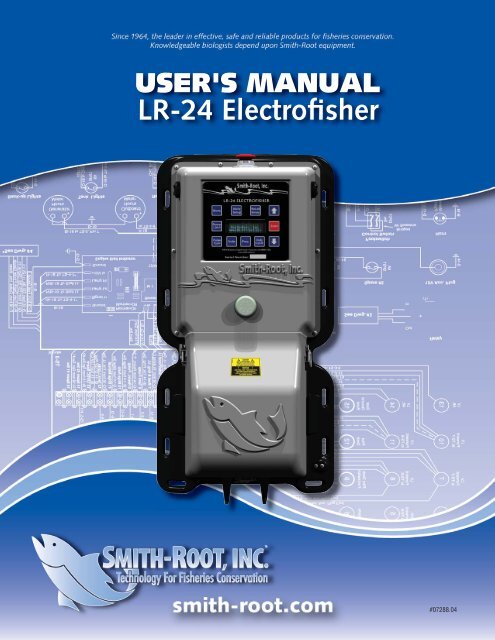
USER'S MANUAL<br />
<strong>LR</strong>-<strong>24</strong> <strong>Electrofisher</strong><br />
#07288.04
Contents<br />
I<br />
Introduction<br />
The <strong>LR</strong>-<strong>24</strong> <strong>Electrofisher</strong> ................................................1<br />
Overview<br />
General Information .............................................. 2 - 4<br />
Status Display<br />
Input ...........................................................................5<br />
Output ........................................................................5<br />
Waveform ...................................................................6<br />
Display Panel Menu<br />
Key Descriptions<br />
Display Panel ...............................................................7<br />
Volts ............................................................................7<br />
Frequency ....................................................................7<br />
Duty Cycle ...................................................................7<br />
Down Arrow ................................................................8<br />
Enter ............................................................................8<br />
Up Arrow ....................................................................8<br />
Recall Set up ................................................................8<br />
Store Set up .................................................................8<br />
System Menus 0-8 .......................................................9<br />
Power Limit ...............................................................14<br />
Pulse Types ................................................................14<br />
Battery Compartment &<br />
Connector Descriptions<br />
Battery Compartment ................................................18<br />
Battery Connector .....................................................18<br />
Anode and Cathode Connectors ................................18<br />
Control Connector .....................................................18<br />
Safety Feature Descriptions<br />
Emergency Shutdown Switch .....................................19<br />
Quick Release Pack Frame .........................................19<br />
Flashing Red Light .....................................................19<br />
Audio Alarm ..............................................................20<br />
Anode Switch ............................................................20<br />
Tilt Switch ..................................................................21<br />
Immersion Sensor ......................................................21<br />
Anode Out of Water .................................................21<br />
Output Voltage Detector ...........................................21<br />
Electronic Circuit Breaker ...........................................21<br />
www.smith-root.com<br />
Battery Compartment Interlock Switches ...................22<br />
Fusible Links ..............................................................22<br />
Temperature Sensors and Overheating ......................22<br />
Peak Current Overload ..............................................23<br />
Output IGBT Failure ..................................................23<br />
Average Current Overload .........................................23<br />
Low Battery Fault ......................................................<strong>24</strong><br />
Set up and Operation<br />
Set up ........................................................................25<br />
Using Recalled Waveforms for Set up ........................28<br />
Factory Default Stored Waveforms ............................29<br />
Custom Set up Procedure ..........................................30<br />
Burst of Pulses Waveforms ........................................32<br />
Dual Output Mode ....................................................34<br />
Storing Waveform Settings ........................................36<br />
Specifications .............................................................37<br />
My Custom Waveforms .............................................38<br />
Battery Care and Maintenance<br />
Charger .....................................................................39<br />
Maintenance Charger & Diagnostic Equipment ..........44<br />
Electrofishing Safety<br />
Safety ........................................................................45<br />
Appendix A<br />
Glossary of Terms ......................................................50<br />
Appendix B<br />
<strong>LR</strong>-<strong>24</strong> Event Codes ....................................................51<br />
Appendix C<br />
<strong>Electrofisher</strong> Operation Hints .....................................52<br />
Appendix D<br />
Factory Default Stored Waveforms ............................53<br />
Appendix E<br />
Pack Adjustments ......................................................54<br />
Appendix F<br />
Cleaning and Maintenance ........................................56<br />
Appendix G<br />
Model 12-B Conversion Chart ...................................56<br />
Appendix H<br />
Electrode Pole Testing ................................................57<br />
Appendix I<br />
Cathode Testing ........................................................57<br />
Appendix J<br />
Anode/Electrode Pole Tester ......................................57
INTRODUCTION<br />
USER'S MANUAL<br />
The <strong>LR</strong>-<strong>24</strong> is the most advanced<br />
<strong>Electrofisher</strong> ever produced. Its design incorporates<br />
many new safety features to help protect both<br />
operating personnel and fish. Many features are<br />
refinements of conventions established in earlier SRI<br />
electrofishers and some are entirely new.<br />
The user interface<br />
has been designed The <strong>LR</strong>-<strong>24</strong> has many features<br />
to make the <strong>LR</strong>-<strong>24</strong> that will increase the collection<br />
easy to use. With capabilities - with greatly<br />
the Quick Set up<br />
enhanced safety to both<br />
feature, the <strong>LR</strong>-<strong>24</strong><br />
operators and wildlife.<br />
automatically sets<br />
output voltage,<br />
frequency and duty cycle. An immersion sensor<br />
automatically turns the output off if the bottom of the pack frame comes into contact with<br />
the water. The anode-out-of-water detector automatically turns off the output if the anode<br />
ring is raised out of the water while the output is on.<br />
Taking the time to familiarize yourself with these features will go a long way towards<br />
learning how to use the <strong>LR</strong>-<strong>24</strong> in the most efficient manner.<br />
Items manufactured by companies other than Smith-Root carry the original manufacturer’s warranty. Please contact<br />
product manufacturer for return instructions.<br />
All Smith-Root, Inc. manufactured products are covered by a one-year warranty.<br />
Credit & Refund Policy: Customers returning equipment - in new condition - will be given a refund within five days from the date of the return. A return<br />
authorization must accompany returns. Valid equipment returns include, but are not limited to, ordering incorrect equipment, funding deficits and defective<br />
equipment returned for reimbursement. All returns are subject to a restocking fee and applicable shipping charges. The restocking fee is figured at 10% of<br />
the purchase price but not less than $20.00. Customers receiving equipment in damaged condition will be referred to the shipping company for insurance<br />
reimbursement.<br />
Rev.04 © 2007 Smith-Root, Inc. Vancouver, WA - USA<br />
www.smith-root.com<br />
1
<strong>LR</strong>-<strong>24</strong><br />
BACKPACK ELECTROFISHER<br />
Overview<br />
<strong>LR</strong>-<strong>24</strong> Controls and Features<br />
Take the time to familiarize yourself with the <strong>LR</strong>-<strong>24</strong>'s features before beginning electrofishing.<br />
1 - Emergency Shutdown Switch<br />
The main on/off switch for the <strong>LR</strong>-<strong>24</strong>. The<br />
switch must be rotated 90 degrees clockwise<br />
to prevent accidentally powering up the unit.<br />
Simply pushing down will turn it off.<br />
2 - Keypad<br />
Allows the display and modification of<br />
many control parameters of the <strong>LR</strong>-<strong>24</strong>.<br />
3 - Menu Display<br />
Displays settings and status of <strong>LR</strong>-<strong>24</strong>.<br />
4 - Flashing Red Light<br />
Flashes to indicate that the output is on.<br />
5 - Battery Compartment Cover<br />
Covers battery and connectors. Must be<br />
properly in place and latched for unit to<br />
function.<br />
6 & 7 - Audio Alarms (Left, right)<br />
Sounds to indicate that the unit is on.<br />
8 - Packframe<br />
Main connecting point for the harness<br />
system. All components are mounted on<br />
the packframe.<br />
9 - Battery Compartment Latch<br />
Three twist-lock latches secure the<br />
battery cover to the main control box and<br />
packframe.<br />
10- Cathode Cable<br />
a molded strain relief allows the cathode<br />
cable to pass through slots in the battery<br />
cover, either in side (as shown), or<br />
bottom.<br />
11- Anode Cable<br />
A molded strain relief allows the anode<br />
cable to pass through slots in the battery<br />
cover, either in side (as shown), or<br />
bottom.<br />
6 2<br />
3<br />
4<br />
9<br />
5<br />
10 11<br />
<strong>LR</strong>-<strong>24</strong> shown without harness system<br />
12<br />
12- Immersion Sensor<br />
This sensor will shut the unit down, should the <strong>LR</strong>-<br />
<strong>24</strong> be immersed in water.<br />
13- Serial Number<br />
Unique number to identify the unit for service.<br />
1<br />
13<br />
7 8<br />
12<br />
2 www.smith-root.com
OVERVIEW<br />
USER'S MANUAL<br />
OVERVIEW<br />
Display Panel Key Overview<br />
The panel has 11 keys that perform a variety of functions. The display is a 4 line 20 character per line<br />
vacuum fluorescent display. The bright blue/green characters can be clearly seen in most lighting situations<br />
but may require shading in direct sunlight.<br />
A<br />
E<br />
Menu<br />
Power<br />
Limit<br />
Pulse<br />
Type<br />
<strong>LR</strong>-<strong>24</strong> ELECTROFISHER<br />
B<br />
Volts<br />
Store<br />
Setup<br />
Freq.<br />
Fig. 1.2 - <strong>LR</strong>-<strong>24</strong> Key pad with fluorescent display<br />
A - Menu Key<br />
Displays the system menu options. Press arrow up<br />
or down to scroll through options. Press menu again<br />
to escape.<br />
B - Store Set up Key<br />
Allows the user to store the settings of the electrofisher<br />
in one of ten storage locations.<br />
C - Recall Set up Key<br />
Recalls one of ten factory default or user stored<br />
electrofisher settings.<br />
C<br />
Recall<br />
Setup<br />
<strong>LR</strong>-<strong>24</strong> <strong>Electrofisher</strong><br />
Smith-Root, Inc.<br />
www.smith-root.com<br />
Duty<br />
Cycle<br />
D<br />
G H I J K<br />
F<br />
Enter<br />
D - Up Arrow Key:<br />
• Increases the selected setting<br />
• Scrolls up through a menu<br />
• Changes to the next status display<br />
E - Power Limit Key<br />
Displays and allows the modification<br />
of the power limit setting.<br />
F - Enter Key<br />
Selects menu items or enters settings<br />
into the selected function and then<br />
returns to the main status display.<br />
G - Pulse Type Key<br />
Displays and allows the modification<br />
of the pulse type setting.<br />
H - Volts Key<br />
Displays and allows the modification<br />
of the voltage setting.<br />
I - Freq. Key<br />
Displays and allows the modification<br />
of the output frequency setting.<br />
J - Duty Cycle Key<br />
Displays the output duty cycle setting<br />
and pulse width in milliseconds.<br />
K - Down Key:<br />
• Decreases the selected setting<br />
• Scrolls down through a menu<br />
• Changes to the previous status<br />
display<br />
See DISPLAY PANEL MENU KEY DESCRIPTIONS for more information on each key.<br />
www.smith-root.com<br />
3
<strong>LR</strong>-<strong>24</strong><br />
BACKPACK ELECTROFISHER<br />
Overview<br />
The <strong>LR</strong>-<strong>24</strong> has many features that will increase the collection capabilities<br />
with greatly enhanced safety to both operators and wildlife.<br />
The <strong>LR</strong>-<strong>24</strong> has better output regulation and<br />
allows greater user control of the output than<br />
any electrofisher before. We suggest that you try<br />
quick set up first. You may find that you use less<br />
voltage and a lower frequency than with other<br />
electrofishers. This should lower fish injury<br />
rates and has the added benefit of longer<br />
shocking time per battery charge.<br />
In all cases, electrofishers should be set<br />
up by observing fish behavior and recovery times, not<br />
by voltage or current measurements.<br />
The <strong>LR</strong>-<strong>24</strong> remembers the settings that were last used and powers up with these settings. There are 10<br />
storage locations for different voltage, frequency and duty cycle set ups for use at any time. The set ups<br />
stored in these locations can be recalled quickly for use at different sites.<br />
A new pack suspension system allows for maximum flexibility and comfort.<br />
New and finer control over the output helps reduce injuries to fish.<br />
Power limit mode allows the user to set a maximum output power level that the <strong>LR</strong>-<strong>24</strong> will not exceed.<br />
Dual output mode lets the user set up 2 different waveforms and voltages and switch from the first to the<br />
second in less than a second by simply double “clicking” (pressing) the anode pole switch. The user can<br />
then switch back to the first waveform and voltage by releasing the anode pole switch for more than one<br />
second, then pressing it again.<br />
4 www.smith-root.com
STATUS DISPLAY<br />
USER'S MANUAL<br />
Status Display<br />
When first turn on the <strong>LR</strong>-<strong>24</strong>, a screen will briefly appear displaying the model number, Software version and<br />
Smith-Root, Inc.s' web address. The status display screen will automatically appear after a few seconds.<br />
The <strong>LR</strong>-<strong>24</strong> has 3 standard screens referred to as "status screens" that are displayed during operation.<br />
Specifically, they are:<br />
The input status screen.<br />
The output status screen.<br />
The waveform screen.<br />
1.) Input Status Screen<br />
A sample input status screen is shown in Fig 1.1.<br />
The first line shows the shocking time in seconds. The <strong>LR</strong>-<strong>24</strong><br />
keeps track of fractions of a second but only displays 1 second<br />
resolution. The second line shows battery condition in a fuel<br />
gauge fashion. <strong>24</strong>.0V or more and the fuel gauge shows full.<br />
At approximately 20.5V the gauge shows empty. At 20.0V the<br />
<strong>LR</strong>-<strong>24</strong> shuts off the output because of a low battery. The third<br />
line is the battery meter. It shows the battery voltage and the<br />
battery current in amps. The <strong>LR</strong>-<strong>24</strong> overloads and shuts off its<br />
output if the battery current reaches 20.0A or more. The fourth<br />
line displays the air temperature in the box and the temperature<br />
of the heat sink.<br />
See Safety Features, under Temperature Sensors for a description<br />
of operating temperatures parameters. Refer to System Menu 4<br />
for an explanation of Thermal Power Foldback feature.<br />
On Time =<br />
Batt. Life =<br />
Batt. = 25.3V 0.1A<br />
Temp.= 74F (70F HS)<br />
Fig. 1.1<br />
2.) Output Status Screen<br />
A sample output status screen is shown in Fig. 1.2.<br />
The first line shows the shocking time in seconds. The second<br />
line shows the average and in parentheses peak power, that the<br />
<strong>LR</strong>-<strong>24</strong> is putting into the water. This peak reading is calculated<br />
by multiplying together the peak output voltage and peak<br />
output current. The average power is calculated by multiplying<br />
the peak power by the duty cycle. The third line shows<br />
the average output voltage and in parentheses the peak output<br />
voltage. The fourth line shows the average output current in<br />
amps and in parentheses the peak output current in amps.<br />
Fig. 1.2<br />
www.smith-root.com<br />
5
<strong>LR</strong>-<strong>24</strong><br />
BACKPACK ELECTROFISHER<br />
Status Display (Cont.)<br />
Fig. 1.3<br />
Output Waveform<br />
DC Output<br />
(Not pulsed)<br />
Volts= 150V<br />
Fig. 1.4<br />
Output Waveform<br />
Burst of= 3 Pulses<br />
(500 Hz 50%) 30Hz<br />
Volts= 150V<br />
Fig. 1.5<br />
3.) Waveform Screen<br />
A sample waveform screen is shown in Fig. 1.3.<br />
The first line will have "output waveform', unless dual output is<br />
turned on (see System Menu 2 - Dual Output). In this case, the<br />
first line will indicate primary waveform or secondary waveform.<br />
The second line describes the type of pulse. There are three types<br />
of pulses, Standard Pulse, DC and Burst of Pulses.<br />
If Standard Pulse has been selected as the output waveform, the<br />
screen will appear as in Figure 1.3. The third line shows the frequency<br />
and duty cycle of the standard pulse. The fourth line shows<br />
the presently selected output voltage.<br />
If DC has been selected as the output waveform, the screen will<br />
appear as in Figure 1.4. The third line will indicate there is no pulse<br />
and the fourth line shows the presently selected output voltage.<br />
If Burst of Pulses has been selected as the output waveform, the<br />
screen will appear as in Figure 1.5. The second line will indicate<br />
the nmber of pulses selected in the burst. The third line will indicate<br />
in parentheses the frequency and duty cycle of the burst of pulses<br />
and the number on the right indicates the frequency of which the<br />
burst of pulses occur. The fourth line shows the currently selected<br />
output voltage.<br />
Menu<br />
Power<br />
Limit<br />
Pulse<br />
Type<br />
Store<br />
Setup<br />
Volts<br />
Freq.<br />
Recall<br />
Setup<br />
Duty<br />
Cycle<br />
Enter<br />
Volts Key<br />
When the Volts key is pressed, the display shows the output voltage<br />
setting and asks for a new setting. Pressing the arrow keys allows<br />
the user to change the output voltage. Pressing the Enter key enters<br />
the settings and returns to the status screen. The range of this control<br />
is from 50 volts to 990 volts in 5 volt steps. Pressing the Volt key a<br />
second time will abort this function and return to the status screen.<br />
Pressing another function key (other than the arrow keys) will abort<br />
this function and move to the set up display for the key that was<br />
pressed.<br />
Volts Key<br />
6 www.smith-root.com
DISPLAY PANEL MENU KEY<br />
USER'S MANUAL<br />
Display Panel Key Descriptions<br />
Freq. Key<br />
When the Freq. key is pressed the display shows the output frequency<br />
setting and asks for a new setting. Pressing the arrow keys allows<br />
the user to change the output frequency. Pressing the Enter key<br />
enters the settings and returns to the status screen. The range of<br />
this control is from 1Hz to 120Hz in 1Hz increments. Pressing<br />
'Freq.' a second time will abort this function and return to the status<br />
screen. Pressing another function key (other than the arrow keys)<br />
will abort this function and move to the set up display for the key<br />
that was pressed.<br />
Menu<br />
Power<br />
Limit<br />
Pulse<br />
Type<br />
Store<br />
Setup<br />
Volts<br />
Freq.<br />
Recall<br />
Setup<br />
Duty<br />
Cycle<br />
Enter<br />
Freq. Key<br />
Fig. 2.1<br />
Duty Cycle Key<br />
When the Duty Cycle key is pressed the display shows the output<br />
duty cycle setting and pulse width in milliseconds and asks for a<br />
new setting. Pressing the arrow keys allows the user to change the<br />
output duty cycle. Pressing the Enter key enters the settings and<br />
returns to the Status Screen. The range of this control is from 1%<br />
or 0.1 milliseconds, whichever is larger, to 99% in 1% increments.<br />
Pressing the Duty Cycle key a second time will abort this function<br />
and return to the Status Screen. Pressing another function key (other<br />
than the arrow keys) will abort this function and move to the set<br />
up display for the function key that was pressed. Duty cycle is the<br />
percentage of time the output pulse is on compared to the time from<br />
the start of one output pulse to the start of the next output pulse. For<br />
example, if the selected waveform is 60 Hz with 25% duty cycle,<br />
an output pulse will occur 60 times per second or once each 16.7<br />
mSec. the pulse width will be .25 X 16.7 mSec. = 4.2 mSec.<br />
Menu<br />
Power<br />
Limit<br />
Pulse<br />
Type<br />
Store<br />
Setup<br />
Volts<br />
Duty Cycle Key<br />
Freq.<br />
Recall<br />
Setup<br />
Duty<br />
Cycle<br />
Enter<br />
Fig. 2.2<br />
www.smith-root.com<br />
7
<strong>LR</strong>-<strong>24</strong><br />
BACKPACK ELECTROFISHER<br />
Display Panel Menu Key Descriptions (Cont.)<br />
q.<br />
Recall<br />
Setup<br />
Fig. 2.3<br />
Fig. 2.4<br />
Duty<br />
Cycle<br />
Menu<br />
Power<br />
Limit<br />
Pulse<br />
Type<br />
Store<br />
Setup<br />
Volts<br />
Store Set up Key<br />
Enter<br />
Up, Enter and Down Keys<br />
Freq.<br />
Recall<br />
Setup<br />
Duty<br />
Cycle<br />
Enter<br />
Down Arrow Key<br />
Decreases the selected setting or scrolls down through a menu or<br />
scrolls to the next status display.<br />
Enter Key<br />
Selects menu items or enters settings into the selected function and<br />
then returns to the main status display. Changes to the settings take<br />
place only after the Enter Key is pressed.<br />
Up Arrow Key<br />
Increases the selected setting or scrolls up through a menu or changes<br />
to the next status display.<br />
Recall Set up Key<br />
Recalls one of ten factory default or user stored electrofisher set ups.<br />
Use the arrow keys to scroll through the set ups and the Enter key to<br />
select the displayed set up. These set ups can be used for different<br />
work areas or streams. Pressing the Recall Set up key a second<br />
time will abort this function and return to the main status display.<br />
Pressing another function key will abort this function and move to<br />
the set up display for the function key that was pressed.<br />
Store Set up Key<br />
The Store Set up key allows the user to store the settings of the<br />
electrofisher in one of ten storage locations. When a setting is<br />
displayed that wish to store, press the Store Set up Key. When the<br />
Store Set up key is pressed, the contents of the first storage location<br />
are displayed. Scroll through the storage locations using the arrow<br />
keys. This will show what is already stored in that location. When<br />
the Enter key is pressed, the set up in the currently displayed storage<br />
area is overwritten and the new voltage, frequency, duty cycle and<br />
waveform settings are stored in this area. This can decrease sample<br />
variations due to set up differences. These settings can be stored for<br />
up to 10 years without power connected to the electrofisher. Pressing<br />
the Store Set up key a second time will abort this function and return<br />
to the Status Screen. Pressing another key (other than the arrow<br />
keys) will abort this function and move to the set up display for the<br />
function key that was pressed. The factory default settings for the<br />
10 storage locations can be restored at any time using the Menu key<br />
and selecting option 7<br />
8 www.smith-root.com
DISPLAY PANEL MENU KEY<br />
USER'S MANUAL<br />
Display Panel Menu Key Descriptions (Cont.)<br />
SYSTEM MENU KEY (0-8)<br />
Allows the user to access additional functions of the <strong>LR</strong>-<strong>24</strong>.<br />
Additional functions include reset the timer, use the quick set up,<br />
access dual output mode, restore factory defaults for waveforms, set<br />
the power limit mode, run extended system diagnostics and examine<br />
the event history. Only one item is displayed at a time. can scroll<br />
through the menu using the arrow keys. Pressing the Enter key<br />
will execute the command and return to the main status display or<br />
display a sub-menu if necessary for that item. Pressing the Menu key<br />
a second time will abort this function and return to the main status<br />
display. Pressing another function key will abort this function and<br />
move to the set up display for the function key that was pressed.<br />
System Menu 0: Time Reset<br />
The reset timer option allows the user to reset the on-time seconds<br />
counter back to zero. Press enter to reset the timer. Press any other<br />
key to exit without resetting the timer (see Figure 2.5).<br />
System Menu 1: Quick Set up<br />
If the Quick Set up option is selected, the <strong>LR</strong>-<strong>24</strong> automatically sets<br />
the waveform, duty cycle and output voltage to suit the present water<br />
conductivity. It will use a default waveform of 30Hz 12% duty cycle<br />
and will adjust the output voltage as necessary to reach 25 watts<br />
average power output. While the <strong>LR</strong>-<strong>24</strong> sets its output up for 25<br />
watts average output power, the power limit is still set at 400 watts<br />
average power. The user may change any of the settings determined<br />
by the <strong>LR</strong>-<strong>24</strong> after the set up cycle is complete. The anode and<br />
cathode should be in the water in a normal operating position when<br />
the Quick Set up cycle is started (see Figures 2.6 and 2.7).<br />
After running Quick Set up, a confirmation message similar to this<br />
appears on the screen.<br />
When this message appears, the <strong>LR</strong>-<strong>24</strong> is ready to begin electrofishing.<br />
may see what settings quick set up chose by using the arrow keys<br />
on the front panel.<br />
Note: As the electrodes move thru the water, the power applied to<br />
the water changes. It may increase well above the initial 25 watt<br />
level or it may decrease well below that level. The output voltage<br />
determined by the Quick Set up routine will be maintained until it<br />
is changed by the user or the power limit is reached or an overload<br />
occurs.<br />
Menu<br />
Power<br />
Limit<br />
Pulse<br />
Type<br />
Menu Key<br />
Fig. 2.5<br />
Fig. 2.6<br />
Fig. 2.7<br />
Store<br />
Setup<br />
Volts<br />
Freq.<br />
Recall<br />
Setup<br />
Duty<br />
Cycle<br />
Enter<br />
www.smith-root.com<br />
9
<strong>LR</strong>-<strong>24</strong><br />
BACKPACK ELECTROFISHER<br />
Display Panel Menu Key Descriptions (Cont.)<br />
Fig. 2.8<br />
Fig. 2.9<br />
System Menu 2 : Dual Output<br />
Dual output on/off allows the user to turn dual output mode on or<br />
off. Dual output mode allows the user to set up and switch between<br />
two completely independent sets of waveforms and voltages by<br />
simply releasing and pressing the anode pole switch in less than 1<br />
second. The primary waveform and voltage, the one entered first,<br />
is the one activated when press the anode pole switch the first time.<br />
The secondary waveform and voltage is activated by releasing and<br />
pressing the anode pole switch in less than 1 second. This feature<br />
allows the user to change voltages and waveforms quickly. This<br />
can help reduce injuries to adults when collecting young of the year.<br />
When using a low frequency waveform to get catfish to move off the<br />
bottom and then quickly changing to a higher frequency waveform to<br />
collect them. Any combination of pulse types, voltages, frequencies,<br />
duty cycles and power limits may be used for the two outputs in dual<br />
output mode. To see or make changes to either the primary or secondary<br />
waveform, from the main status waveform screen, press the<br />
Up arrow key until the display shows the primary waveform. Make<br />
changes using the volts, freq. and duty cycle keys. Pressing the Up<br />
arrow key one more time will display the secondary waveform and<br />
may make changes to it in the same way the primary waveform was<br />
changed. To change back to the primary waveform, release the pole<br />
switch for more than 1 second and then press it again.<br />
System Menu 3: Power Limit Mode<br />
This menu item allows the user to select the method for controlling<br />
the maximum average output power of the <strong>LR</strong>-<strong>24</strong>. If the user-set<br />
power limit is reached, the <strong>LR</strong>-<strong>24</strong> will automatically decrease the<br />
output voltage or frequency, as selected by the user, to maintain the<br />
output power at that limit. If the output power drops below the limit<br />
then the <strong>LR</strong>-<strong>24</strong> will automatically increase the voltage or frequency<br />
back to the user set value.<br />
Fig. 2.10<br />
System Menu 4: Thermal Power Fold Back Mode<br />
This menu option allows the user to turn Thermal Power Limiting<br />
on or off. On hot days, when the <strong>LR</strong>-<strong>24</strong> is putting out 200 watts or<br />
more, it may eventually overheat and shut down to prevent possible<br />
damage to the electronics. Thermal Power Limiting allows the <strong>LR</strong>-<br />
<strong>24</strong> to better control the amount of internal heat being produced and<br />
in many cases can prevent thermal shutdown. This feature allows the<br />
<strong>LR</strong>-<strong>24</strong> to continue to function in hot environments where it would<br />
otherwise shutdown. When this option is turned on the <strong>LR</strong>-<strong>24</strong> will<br />
automatically reduce its output frequency if one of the pulsed outputs<br />
10 www.smith-root.com
DISPLAY PANEL MENU KEY<br />
USER'S MANUAL<br />
Display Panel Menu Key Descriptions (Cont.)<br />
has been selected or it will reduce its output voltage if DC output<br />
has been selected. The <strong>LR</strong>-<strong>24</strong> reduces the output by 20% for every<br />
2 degree Fahrenheit above the trip point, up to a maximum of 80%<br />
reduction.<br />
The <strong>LR</strong>-<strong>24</strong> has two thermal sensors inside: one monitors the air<br />
temperature inside the electronics cover and the other monitors the<br />
temperature of the heat sink. The trip points are 150 degrees for the<br />
air temperature and 190 degrees for the heat sink temperature. The<br />
shutdown temperature for the air is 160 degrees and 200 degrees for<br />
the heat sink. If either of the shut down temperatures is reached, the<br />
<strong>LR</strong>-<strong>24</strong> will shut down even if Thermal Power Limiting is enabled.<br />
With Thermal Power Fold Back enabled when either of the trip<br />
points is reached, the <strong>LR</strong>-<strong>24</strong> will begin to beep both audio alarms<br />
simultaneously and the status screen will look similar to that shown<br />
in Figure 2.11.<br />
Fig. 2.11<br />
This display says that the <strong>LR</strong>-<strong>24</strong> has entered thermal power limiting.<br />
The output frequency has been reduced by 20%. The output<br />
frequency was set to 60Hz and has been reduced to 48 Hz. The<br />
average output current is 1.26 amps and the peak output current<br />
is 5.83 amps. If the temperature continues to rise, the <strong>LR</strong>-<strong>24</strong> will<br />
continue to reduce the output in 20% steps to a maximum of 80%.<br />
This status display can be seen as long as the pole switch is pressed.<br />
When the pole switch is released, the standard status screen will<br />
return. This allows continued monitoring of battery condition, or<br />
the temperature of the <strong>LR</strong>-<strong>24</strong>. As the <strong>LR</strong>-<strong>24</strong> cools down the output<br />
is automatically increased back toward the original settings. The<br />
<strong>LR</strong>-<strong>24</strong> will not increase the output beyond the original settings.<br />
Fig. 2.12<br />
System Menu 5: Anode Out Of Water Disable<br />
Allows the temporary override of the Anode Out of Water feature.<br />
This option allows the <strong>LR</strong>-<strong>24</strong> to be used in very shallow water, where<br />
it may not be possible to keep the anode in the water all of the time.<br />
This option is only active while the <strong>LR</strong>-<strong>24</strong> is powered on and the<br />
mode resets to “Enabled” on power up.<br />
www.smith-root.com<br />
11
<strong>LR</strong>-<strong>24</strong><br />
BACKPACK ELECTROFISHER<br />
Display Panel Menu Key Descriptions (Cont.)<br />
Fig. 2.13<br />
Fig. 2.14<br />
System Menu 6: Extended System Test<br />
This is a diagnostic test mode for test and service technicians. It<br />
requires the use of a standardized test load connected to the anode<br />
and cathode.<br />
During the test the <strong>LR</strong>-<strong>24</strong> checks its program memory for errors, then<br />
it checks the operation of the output safety relay, the output switch<br />
(IGBT), the accuracy of the five internal voltage ranges, estimates the<br />
charge in the battery and measures the efficiency of the high voltage<br />
converter. This test takes approximately 20 seconds to run. To run<br />
the test, follow the instructions on the screen. See Figure 2.13.<br />
The user must press the Up arrow key to continue the test pressing<br />
any other key will abort the test and return to the status display<br />
(Figs. 2.14-2.15).<br />
Followed in a few seconds by the screen in Fig. 2.18.<br />
Fig. 2.15<br />
If the relays and regulation pass the test, the following message will<br />
appear on the display, indicating the first series of testing passed<br />
(Fig. 2.17).<br />
The next part of the test requires that the output of the <strong>LR</strong>-<strong>24</strong> be<br />
connected to a test load or that the electrodes be in water. This part<br />
of the test takes about 15 seconds to complete. When it is finished,<br />
the output of the <strong>LR</strong>-<strong>24</strong> will automatically turn off.<br />
Fig. 2.16<br />
If the <strong>LR</strong>-<strong>24</strong> passes this part of the test this message will be displayed.<br />
(Fig. 2.18)<br />
This information is displayed for as long as the pole switch is held<br />
down.<br />
The use of a non-standard test load or electrodes in water will<br />
probably yield different efficiency numbers.<br />
Fig. 2.17<br />
Fig. 2.18<br />
12 www.smith-root.com
DISPLAY PANEL MENU KEY<br />
USER'S MANUAL<br />
Display Panel Menu Key Descriptions (Cont.)<br />
System Menu 7: Restoring Factory Default Settings<br />
Restore factory defaults restores the original factory set voltages and<br />
waveforms in the 10 waveform storage locations. All the current<br />
settings will be changed back to the Factory Default Settings. See<br />
Appendix D for a list of Factory Default Settings.<br />
Fig. 2.19<br />
This message will be displayed before the default settings are restored<br />
and the user must press the Up arrow key to confirm restoration of t<br />
those settings (See Fig. 2.20). Pressing any other key will abort this<br />
operation and return to the status display.<br />
Fig. 2.20<br />
System Menu 8: Event History<br />
The <strong>LR</strong>-<strong>24</strong> records all errors and unusual events that occur during<br />
use. This menu option allows a technician to review the status codes<br />
stored during field use of the <strong>LR</strong>-<strong>24</strong> (See Fig. 2.21).<br />
This history file is an aid to troubleshooting if the <strong>LR</strong>-<strong>24</strong> develops<br />
a problem. There is a table of error codes in Appendix B of this<br />
manual. To exit from this mode and return to the status screen. Press<br />
the enter key (See Fig. 2.22).<br />
Fig. 2.21<br />
Fig. 2.22<br />
www.smith-root.com<br />
13
<strong>LR</strong>-<strong>24</strong><br />
BACKPACK ELECTROFISHER<br />
Display Panel Menu Key Descriptions (Cont.)<br />
Power Limit Key<br />
The Power Limit Key allows the user to pre-set an output limit where<br />
desired out of safety considerations.<br />
When the Power Limit key is pressed, the setting is displayed and can<br />
be changed by using the arrow and Enter keys.<br />
Fig. 2.23<br />
Menu<br />
Power<br />
Limit<br />
Pulse<br />
Type<br />
Store<br />
Setup<br />
Volts<br />
Freq.<br />
Recall<br />
Setup<br />
Duty<br />
Cycle<br />
Enter<br />
Pressing the Power Limit key again will abort this function and return<br />
to the main status display. Pressing another key will abort this function<br />
and move to the set up display of the key that was pressed. The power<br />
is limited by lowering the output voltage or frequency, which the user<br />
selects from the Limit Mode option under the Menu key. The minimum<br />
output voltage is 50 volts. If this lower voltage limit is reached and the<br />
power limit is still being exceeded, the <strong>LR</strong>-<strong>24</strong> will shutdown its output<br />
and an error message will be displayed. This control does not affect<br />
the output unless the user set power limit is reached. The power limit<br />
cannot be set higher than 400 watts average output power.<br />
Power Limit Key<br />
In Burst of Pulses mode, if the power limit is reached and if the limit<br />
mode is set to frequency, only the cycle frequency will be reduced. The<br />
frequency of the pulses in the burst is not changed. For an explanation<br />
of cycle and burst frequencies, see Pulse Type, below.<br />
Fig. 2.<strong>24</strong><br />
Menu<br />
Power<br />
Limit<br />
Store<br />
Setup<br />
Recall<br />
Setup<br />
Enter<br />
Pulse Type Key<br />
Allows the user to Enter the output waveform of the <strong>LR</strong>-<strong>24</strong>. Available<br />
waveforms are DC, Standard Pulse and Burst of Pulses.<br />
The output pulse type can be changed by using the Up or Down arrow<br />
keys. When DC is selected, the output of the <strong>LR</strong>-<strong>24</strong> is smooth DC at<br />
the selected voltage and power limit settings.<br />
Standard Pulse is a waveform that produces continuous output pulses<br />
of the selected voltage, duty cycle, frequency and power limit. For<br />
example, 60Hz 25% duty cycle 300 volts and 100 watts average power<br />
limit, would produce a 300 Volt pulse 4.2 milliseconds wide, (25% duty<br />
cycle), 60 times per second unless the power limit of 100 watts average<br />
power is reached. If the power limit is reached then the <strong>LR</strong>-<strong>24</strong> will<br />
automatically reduce the output voltage or frequency, whichever one<br />
the user has selected, to maintain 100 watts average output power.<br />
Pulse<br />
Type<br />
Volts<br />
Freq.<br />
Duty<br />
Cycle<br />
Pulse Type Key<br />
14 www.smith-root.com
DISPLAY PANEL MENU KEY<br />
USER'S MANUAL<br />
Display Panel Menu Key Descriptions (Cont.)<br />
Burst of Pulses<br />
Burst of Pulses is a complex waveform wherein a lower frequency<br />
waveform is used to turn on and off a higher frequency waveform.<br />
The lower frequency is called the cycle frequency. The higher<br />
frequency is called the burst frequency. For example, a burst of 3<br />
pulses at 400 Hz with a 12% duty cycle and a 40 Hz cycle frequency<br />
would produce the following output:<br />
A pulse would occur every 2.5 milliseconds, (400 Hz) and<br />
each pulse would be 0.3 milliseconds wide, (12% of the 400<br />
Hz). After the first 3 pulses of the 400 Hz waveform the next 7<br />
pulses of this waveform would be skipped. Then there would be<br />
another 3 pulses of the 400 Hz 12% duty cycle waveform. For<br />
this waveform the bursts of pulses occur every 25 milliseconds,<br />
(40 Hz). This pattern would repeat as long as the switch on the<br />
anode pole was held down. For this example, the <strong>LR</strong>-<strong>24</strong> could<br />
not output more than 10 pulses of the 400 Hz burst because 400<br />
Hz is only 10 times the cycle frequency of 40 Hz.<br />
Fig. 2.25<br />
Fig. 2.26<br />
As a second example, if the <strong>LR</strong>-<strong>24</strong> were set to produce a burst of<br />
5 pulses at 250 Hz and 10% duty cycle at a 15 Hz cycle frequency,<br />
the waveform would have these characteristics:<br />
A pulse would occur every 4 milliseconds, (250 Hz), each pulse<br />
would be 0.4 milliseconds wide, (10% of the 250 Hz). After<br />
5 pulses of the 250 Hz waveform, the next 11 pulses of this<br />
waveform would be skipped. Then there would be another<br />
5 pulses of the 250 Hz 10% duty cycle waveform. For this<br />
waveform, the bursts of pulses occur every 67 milliseconds (15<br />
Hz). This pattern would repeat as long as the switch on the anode<br />
pole was held down. For this example, the <strong>LR</strong>-<strong>24</strong> could not put<br />
out more than 16 pulses of the 250 Hz burst because 250 Hz is<br />
only 16.67 times the cycle frequency of 15 Hz.<br />
www.smith-root.com<br />
15
<strong>LR</strong>-<strong>24</strong><br />
BACKPACK ELECTROFISHER<br />
Display Panel Menu Key Descriptions (Cont.)<br />
Fig. 2.27<br />
Fig. 2.28<br />
If you select more burst pulses than possible at the selected cycle<br />
frequency (the low frequency), the <strong>LR</strong>-<strong>24</strong> will automatically increase<br />
the burst frequency (the high frequency), to allow the selected number<br />
of pulses to be output. The <strong>LR</strong>-<strong>24</strong> will not allow users to choose a<br />
burst frequency that is too low to produce the number of pulses that<br />
have been selected at the cycle frequency selected.<br />
The following example demonstrates how to set up a Burst of<br />
Pulses:<br />
1. Press the Pulse Type key on the front of the <strong>LR</strong>-<strong>24</strong>. Use the<br />
arrow keys to select Burst of Pulses for the new pulse type. The<br />
display will look like this:<br />
2. Press the Enter key.<br />
3. Press the Volts key and use the arrow keys to set the voltage to<br />
150 volts, then press the Enter key.<br />
Fig. 2.29<br />
4. Press the Freq.key and use the arrow keys to set the cycle<br />
frequency to 40 Hz, then press the Enter key.<br />
5. Press the Duty Cycle key and use the arrow keys to set the number<br />
of pulses to 5, then press the Enter key.<br />
Fig. 2.30<br />
6. Use the arrow keys to set the burst frequency to 400Hz, then<br />
press the Enter key.<br />
Fig. 2.31<br />
16 www.smith-root.com
DISPLAY PANEL MENU KEY<br />
USER'S MANUAL<br />
Display Panel Menu Key Descriptions (Cont.)<br />
7. Use the arrow keys to set the duty cycle of the burst pulses to<br />
25%, then press the Enter key.<br />
Fig. 2.32<br />
8. You can now use the arrow keys to review the settings for the<br />
burst of pulses.<br />
Fig. 2.33<br />
Figure 2.34 shows the waveform that was set up in the preceding example. The lone pulse on the right<br />
side of the figure is the first pulse of the next group of 5 pulses. The height of each pulse is 150 volts. The<br />
groups of 5 pulses repeat at a 40Hz rate. Each one of the individual pulses is on for 25% of the time from<br />
the start of one pulse to the start of the next pulse in the group.<br />
Fig. 2.34<br />
www.smith-root.com<br />
17
<strong>LR</strong>-<strong>24</strong><br />
BACKPACK ELECTROFISHER<br />
Battery Compartment and Connections<br />
Fig. 3.1<br />
Fig. 3.2<br />
Cathode<br />
Connector<br />
Fig. 3.3<br />
Anode<br />
Connector<br />
Control<br />
Connector<br />
Battery<br />
Connector<br />
Battery Compartment<br />
Opening the battery compartment allows the user to install or<br />
change the battery, or connect the anode, cathode and control circuit<br />
connectors. Remove the battery compartment cover by flipping the<br />
handles on the 3 cam-lock latches out and turning them counterclockwise.<br />
Make sure the latch on the bottom of the cover is free,<br />
then pull out on the 2 side latches and lift the battery compartment<br />
cover away from the <strong>LR</strong>-<strong>24</strong>.<br />
When replacing the battery compartment cover adjust it so that it<br />
is on the inside of the molded guides of the pack frame. The cover<br />
must be correctly placed before the <strong>LR</strong>-<strong>24</strong> will operate.<br />
Close the cover latches.<br />
Battery Connector<br />
The battery connector, located inside the battery compartment, is a<br />
rectangular red and black plastic connector on the end of the input<br />
power cable. It mates with an identical connector on the <strong>LR</strong>-<strong>24</strong><br />
battery packs. This connector is color coded and polarized to prevent<br />
accidental reverse connections of the battery.<br />
Anode and Cathode Connectors<br />
The anode and cathode connectors are black plastic circular 2-pin<br />
connectors located on the bulkhead between the battery compartment<br />
and the electronics compartment. Access to these connectors is<br />
gained by removing the battery compartment cover. The connectors<br />
are identical and allow the use of a trailing cathode cable or a cathode<br />
pole for greater control over placement of the output electric field.<br />
Both pins in these connectors are live when the <strong>LR</strong>-<strong>24</strong> is on. These<br />
connectors are polarized, 1/4 turn, locking connectors.<br />
Control Connector<br />
The control connector is a smaller 4-pin version of the anode and<br />
cathode connectors. It is also polarized and the smaller size prevents<br />
incorrect connections. The <strong>LR</strong>-<strong>24</strong> utilizes a low voltage control<br />
circuit for added safety<br />
18 www.smith-root.com
SAFETY FEATURES<br />
USER'S MANUAL<br />
Emergency Shutdown Switch<br />
The large red mushroom switch located on the top of the <strong>LR</strong>-<strong>24</strong><br />
is the Emergency Shutdown Switch, which is also the main on/off<br />
switch for the <strong>LR</strong>-<strong>24</strong>. To turn the power on the user must rotate the<br />
switch 90 degrees in the direction of the arrows (clockwise). Since<br />
the switch knob must be rotated, it helps to prevent accidentally<br />
powering up the <strong>LR</strong>-<strong>24</strong>. Pushing the red mushroom knob down<br />
until it latches will immediately turn the <strong>LR</strong>-<strong>24</strong> off.<br />
SAFETY FEATURES<br />
Fig. 4.1<br />
Quick Release Pack Frame<br />
The <strong>LR</strong>-<strong>24</strong> has an integral quick release pack frame. Just press the<br />
latch tabs on the waist belt and shoulder straps and the entire <strong>LR</strong>-<strong>24</strong><br />
falls away.<br />
CAUTION: Always unlatch the chest strap of the pack before entering<br />
or crossing water. If left latched this strap may prevent the user<br />
from quickly removing the <strong>LR</strong>-<strong>24</strong> in the event of an emergency, such<br />
as falling into deep water.<br />
Chest Strap<br />
(Remove<br />
before<br />
entering<br />
water)<br />
Quick<br />
Release<br />
Fig. 4.2<br />
Flashing Red Light<br />
Bright long life LED lamps flash whenever the <strong>LR</strong>-<strong>24</strong> is turned on<br />
and 30 volts or more is present between the anode and cathode.<br />
Fig. 4.3<br />
www.smith-root.com<br />
19
<strong>LR</strong>-<strong>24</strong><br />
BACKPACK ELECTROFISHER<br />
Safety Features Descriptions (cont.)<br />
SAFETY DO'S AND<br />
DON'T'S<br />
Do’s:<br />
1. Always be sure that all personnel<br />
are clear of the electrodes before<br />
turning on the power.<br />
2. Know how to administer first aid<br />
treatment for electrical shock.<br />
3. Wear flotation devices.<br />
4. Have electrical circuits checked<br />
only by qualified technicians.<br />
5. Disconnect the power supply when<br />
the electrofisher is not in use.<br />
Don’ts:<br />
1. Don’t electrofish alone!<br />
2. Don’t continue to electrofish if the<br />
boots or gloves get wet inside.<br />
3. Don’t operate an electrofisher if<br />
have had any prior heart ailments.<br />
4. Don’t electrofish when are tired.<br />
ON<br />
Audio Alarm<br />
The audio output alarm indicates 4 different <strong>LR</strong>-<strong>24</strong> operating<br />
conditions and is composed of two tone-emitting units; one high<br />
pitched and the other low pitched.<br />
1. Presence of high voltage in the water<br />
Whenever the anode and cathode are in the water<br />
and more than 30 volts is present, there will be<br />
an audible tone emitted by the alarm.<br />
2. Average power output level<br />
The Audio Alarms emit pulsed tones to indicate average power<br />
output level:<br />
Average power output level<br />
Watts Audio Tone in secs.<br />
0 to 99.9 1 pulse per second<br />
100 to 199.9 2 pulses per second<br />
200 to 299.9 3 pulses per second<br />
300 to 400 4 pulses per second<br />
3. Power Limit mode: When the <strong>LR</strong>-<strong>24</strong> output power reaches<br />
the user set power limit, the audio tone alternates between the<br />
high and low pitch at the rates specified above.<br />
4. Dual Output mode: In this mode, the <strong>LR</strong>-<strong>24</strong> can operate<br />
with a primary or secondary user-specified voltage/waveform<br />
combination. The selection between the two combinations is<br />
accomplished by rapidly double pressing the anode pole switch.<br />
The primary voltage/waveform is assigned to the high-pitched<br />
tone and the secondary voltage/waveform is assigned to the lowpitched<br />
tone.<br />
Fig. 5.1<br />
OFF<br />
Anode Switch<br />
A magnetic reed switch is used for the anode pole switch. This<br />
switch has direct shutdown control of the high voltage output<br />
safety relay inside the <strong>LR</strong>-<strong>24</strong>. Releasing the flapper for the switch<br />
turns the switch off.<br />
20 www.smith-root.com
SAFETY FEATURES<br />
USER'S MANUAL<br />
Safety Features Descriptions (Cont.)<br />
Tilt Switch<br />
The tilt switch automatically turns off the output of the <strong>LR</strong>-<strong>24</strong> if the<br />
<strong>LR</strong>-<strong>24</strong> is tipped too far from vertical in any direction. The maximum<br />
forward tilt is 55 degrees from vertical. The maximum backward<br />
tilt is 35 degrees from vertical. The maximum side to side tilt is 45<br />
degrees from vertical +/- 10 degrees.<br />
If tilted beyond these limits, an error message is displayed. This<br />
condition is reset by moving to a more vertical position and releasing<br />
and pressing the anode pole switch.<br />
55°<br />
35°<br />
Immersion Sensor<br />
If the lower end of the <strong>LR</strong>-<strong>24</strong> comes into contact with the water, the<br />
output is automatically shut off and an error message is displayed.<br />
This condition is reset by moving the <strong>LR</strong>-<strong>24</strong> case out of contact<br />
with the water and then turning the power off and back on again.<br />
Note that if the battery compartment has filled with water, it must<br />
be drained before resetting the <strong>LR</strong>-<strong>24</strong>.<br />
Anode Out of Water<br />
This feature disables the output of the <strong>LR</strong>-<strong>24</strong> and displays an error<br />
message whenever the anode pole switch is depressed and less than<br />
30 milliamps, mA, of current is flowing between the anode and<br />
cathode. To restart the <strong>LR</strong>-<strong>24</strong>, place the electrode in the water and<br />
press the anode pole switch.<br />
For working in very shallow water, this feature can be turned off<br />
using System Menu 5: Anode Out of Water Disable.<br />
Note: This function is reactivated automatically when battery power<br />
is turned off and back on.<br />
Output Voltage Detector<br />
This circuit senses voltage between the anode and cathode of the<br />
<strong>LR</strong>-<strong>24</strong> and activates the audio alarm and a flashing red light if the<br />
<strong>LR</strong>-<strong>24</strong> is turned on. Minimum detection voltage is 30 volts. This<br />
will occur whenever 30 volts is present in the water, regardless of<br />
whether the <strong>LR</strong>-<strong>24</strong> is turned on or not.<br />
Electronic Circuit Breaker<br />
The input of the <strong>LR</strong>-<strong>24</strong> is protected by an electronic circuit breaker<br />
which shuts off all power to the <strong>LR</strong>-<strong>24</strong> in the event of excessive<br />
battery drain. The breaker trips at an input current of 27 amps.<br />
Immersion Sensor<br />
Fig. 5.3<br />
Fig. 5.2<br />
Fig. 5.4<br />
www.smith-root.com<br />
21
<strong>LR</strong>-<strong>24</strong><br />
BACKPACK ELECTROFISHER<br />
Safety Features Descriptions (Cont.)<br />
The <strong>LR</strong>-<strong>24</strong> and Temperature<br />
Fig. 5.5<br />
If the <strong>LR</strong>-<strong>24</strong> is working hard on hot days, it<br />
may overheat and shut down.<br />
If the air temperature in the box reaches 160F<br />
or if the heat sink reaches 200F, an overtemperature<br />
error message will be displayed<br />
and the output will be disabled until the <strong>LR</strong>-<strong>24</strong><br />
cools down.<br />
When using any of the pulsed outputs, the<br />
<strong>LR</strong>-<strong>24</strong> can reduce the frequency of the output<br />
pulses automatically based on its internal<br />
temperature. This has the effect of reducing<br />
the power level of the <strong>LR</strong>-<strong>24</strong> and therefore the<br />
heat being produced inside the system.<br />
This can allow the <strong>LR</strong>-<strong>24</strong> to continue to work<br />
instead of waiting for it to cool down again.<br />
This power reduction does not begin until the<br />
<strong>LR</strong>-<strong>24</strong> is near the point of thermal overload,<br />
so under most conditions it does not affect the<br />
output at all. If unpulsed DC is being used<br />
the <strong>LR</strong>-<strong>24</strong> can reduce the output voltage if<br />
it is near thermal overload. Again ,this can<br />
allow the <strong>LR</strong>-<strong>24</strong> to continue working instead<br />
of waiting for it to cool down. In both modes<br />
of operation as the <strong>LR</strong>-<strong>24</strong> cools down, the<br />
output is increased back toward the original<br />
settings.<br />
When enabled and the temperature of the <strong>LR</strong>-<br />
<strong>24</strong> reaches the trip point, both of the audio<br />
alarms will begin to beep simultaneously and<br />
the Thermal Limit display will show the<br />
set frequency, or voltage, in the case of DC<br />
Continued on next page...<br />
Battery Compartment Interlock Switches<br />
The cover of the battery compartment contains an interlock<br />
mechanism (A) that automatically turns off power to the<br />
<strong>LR</strong>-<strong>24</strong> if the cover is opened. When replacing the battery<br />
compartment cover, adjust it so that it is on the inside of the<br />
molded guides (B) of the pack frame. The cover must be<br />
correctly placed before the <strong>LR</strong>-<strong>24</strong> will operate.<br />
RIGHT: Detail<br />
showing relative<br />
A<br />
locationsof Interlock<br />
Switch inside control<br />
box (not visible) and<br />
A<br />
magnet inside of lid.<br />
B<br />
LEFT:Detail showing<br />
molded guides on pack<br />
frame. Lid must be aligned<br />
correctly and latched for<br />
unit to operate.<br />
Fusible Links<br />
The battery pack of the <strong>LR</strong>-<strong>24</strong> incorporates a fusible link<br />
to protect the batteries from excessively high currents. In<br />
the event this fusible link blows out, it must be replaced<br />
with the same size and type as the original link in order to<br />
continue to provide protection for the battery pack and its<br />
wiring.<br />
WARNING: Replacement of this link by anyone other<br />
than Smith-Root, Inc. will void the warranty of the entire<br />
electrofishing system.<br />
Temperature Sensors<br />
There are internal temperature sensors which can shut the <strong>LR</strong>-<br />
<strong>24</strong> down if excessive temperatures are detected; If the <strong>LR</strong>-<strong>24</strong><br />
is shut down due to high temperature, an error message is<br />
displayed for as long as the temperature is above safe limits.<br />
After the <strong>LR</strong>-<strong>24</strong> has cooled, the error message is cleared and<br />
full operation is automatically restored.<br />
The Thermal Foldback Mode (System Menu 4) can<br />
help decrease the chance of shutdown due to excessive<br />
temperatures.<br />
22 www.smith-root.com
SAFETY FEATURES<br />
USER'S MANUAL<br />
Safety Features Descriptions (Cont.)<br />
Fault Conditions<br />
Peak Current Overload<br />
If the peak output current exceeds 40 amps, the output is disabled<br />
and an error message is displayed (See Fig. 5.6).<br />
This is usually caused by a short circuit between the anode and cathode.<br />
The <strong>LR</strong>-<strong>24</strong> can be reset by releasing the switch on the anode<br />
pole and pressing it again.<br />
Fig. 5.6<br />
Output IGBT Failure<br />
If there is an Output Switch (IGBT) Failure, the <strong>LR</strong>-<strong>24</strong>’s output<br />
is shut off and an error message is displayed (See Fig. 5.7).<br />
The criteria for an Output Switch Fault is that output voltage has been<br />
detected when there should be none. For example, if the anode pole<br />
switch is not activated, there should be no output from the <strong>LR</strong>-<strong>24</strong>.<br />
If, however, output is detected, then an Output Switch Fault exists<br />
and the <strong>LR</strong>-<strong>24</strong>’s output will be disabled. The <strong>LR</strong>-<strong>24</strong> must then be<br />
sent back to Smith-Root for repair. Do not attempt to use the <strong>LR</strong>-<strong>24</strong><br />
if this message appears, as a safety hazard may exist and further use<br />
may cause more damage to the <strong>LR</strong>-<strong>24</strong>.<br />
Average Current Overload<br />
The input and output currents of the <strong>LR</strong>-<strong>24</strong> are constantly monitored<br />
while in use. If these currents become excessive, the <strong>LR</strong>-<strong>24</strong> will<br />
shutdown it’s output to prevent damage to it’s circuits. Releasing<br />
the pole switch and selecting a lower output voltage or lower duty<br />
cycle waveform should clear this fault (See Fig. 5.8).<br />
Fig. 5.7<br />
Fig. 5.8<br />
Temperature continued<br />
output and the reduced frequency<br />
or voltage based on the internal<br />
temperature of the <strong>LR</strong>-<strong>24</strong>. This<br />
display is shown as long as the<br />
pole switch is pressed. When the<br />
switch is released the standard status<br />
display is shown. This allows to see<br />
what the <strong>LR</strong>-<strong>24</strong> is doing and what<br />
the internal temperatures are. It also<br />
allows users to continue to monitor<br />
the battery if desired. This option<br />
is explained in greater depth under<br />
System Menu 4.<br />
www.smith-root.com<br />
23
<strong>LR</strong>-<strong>24</strong><br />
BACKPACK ELECTROFISHER<br />
Safety Features Descriptions (Cont.)<br />
Fig. 5.9<br />
Fig. 5.10<br />
Inverter Overload<br />
If the Output Voltage is set too high for the water conductivity and the<br />
electrode spacing, the <strong>LR</strong>-<strong>24</strong> will turn off its output and display an error<br />
message (see Fig. 5.9). The error message will suggest a more appropriate<br />
voltage for the present conditions. If this error is caused by a mistake, for<br />
example, temporarily having the Anode and Cathode too close together,<br />
acknowledge the error message by releasing the pole switch and pressing<br />
any key on the keypad.<br />
If the the error message shows up again in a short time, acknowledge the<br />
message and reduce settings to the suggested voltage before proceeding.<br />
This message occurs when the output voltage drops more than 30% below<br />
the voltage the user has set on the <strong>LR</strong>-<strong>24</strong>. This occurs when the water<br />
conductivity or electrode spacing (or both) are such that more power is<br />
being required from the <strong>LR</strong>-<strong>24</strong> than it can supply. Note the average and<br />
peak power readings on the display. While the average power may be quite<br />
low, the peak power will be far above the 400 watts the <strong>LR</strong>-<strong>24</strong> can supply<br />
on a continous basis.<br />
Low Battery Fault<br />
When the battery is less than 20V, the <strong>LR</strong>-<strong>24</strong> will shut down its<br />
output and display the Low Battery message (see Fig. 5.10).<br />
Fig. 5.8<br />
Fig. 5.11<br />
Turn off the power and replace the battery with one fully charged<br />
to clear this fault.<br />
Battery Current Too Low<br />
If the input current measuring circuit does not measure any current,<br />
this error message will appear and the power to the <strong>LR</strong>-<strong>24</strong> will have<br />
to be turned off and back on to clear the message (see Fig. 5.11).<br />
This test is included to detect problems in the input current sensing<br />
circuit. If this error message appears again, the <strong>LR</strong>-<strong>24</strong> will have to<br />
be sent to SRI for repairs.<br />
<strong>24</strong> www.smith-root.com
SET UP & OPERATION<br />
USER'S MANUAL<br />
Set up and Operation<br />
Make sure the Electrode ring is clean and shiny. A cloudy dull-gray<br />
Electrode ring will reduce catch per unit effort and will increase<br />
the fish injury rate. Initial set up of voltage, frequency, duty cycle<br />
and waveform should be done outside of the sample area to avoid<br />
influencing the statistics.<br />
Basic Set up of the <strong>LR</strong>-<strong>24</strong>:<br />
1. Make sure the power switch on the top of the <strong>LR</strong>-<strong>24</strong> is in the<br />
OFF position (pressed DOWN).<br />
2. Attach the anode and cathode to their output connectors. Attach<br />
the smaller connector on the anode cable to the control connector<br />
of the <strong>LR</strong>-<strong>24</strong>. Determine desired position of anode<br />
and cathode cables. They can be set up to exit the battery<br />
compartment either from the bottom or the sides. To run the<br />
cables out the bottom of the battery compartment, place the<br />
cables in the molded troughs, then install the battery and attach<br />
the power cord. Place the strain reliefs of the anode and cathode<br />
cables in the slots at the bottom of the pack frame, adjust the<br />
battery cover so that it is on the inside of the molded guides of<br />
the pack frame. The cover must be correctly placed before the<br />
<strong>LR</strong>-<strong>24</strong> will operate (see figures 6.1 and 6.2). To run cables out<br />
the sides of the battery compartment, install the battery and<br />
attach the power cord of the <strong>LR</strong>-<strong>24</strong> then route the cables thru<br />
the slots in the sides of the battery compartment cover. Adjust<br />
the battery cover so that it is on the inside of the molded guides<br />
of the pack frame. The cover must be correctly placed before<br />
the <strong>LR</strong>-<strong>24</strong> will operate. Close the cover latches (see figures 6.3<br />
and 6.4).<br />
3. Put the <strong>LR</strong>-<strong>24</strong> on. Be sure to know the location of the quick<br />
release buckles for the backpack and unlatch the chest strap<br />
before entering or crossing the water (refer to Appendix E:<br />
Pack Adjustments for further instructions).<br />
4. Check with each crew member to be sure they know are ready<br />
to turn on the power.<br />
Fig. 6.1<br />
Cathode<br />
connector<br />
Fig. 6.2<br />
Fig. 6.3<br />
Fig. 6.4<br />
Control<br />
connector<br />
Anode<br />
connector<br />
www.smith-root.com<br />
25
<strong>LR</strong>-<strong>24</strong><br />
BACKPACK ELECTROFISHER<br />
Set up and Operation (Cont.)<br />
Fig. 6.5<br />
Fig. 6.6<br />
5. Turn on the power. Do not press the anode switch. Check<br />
the operation of the tilt switch by bending forward until the tilt<br />
switch activates, (about 55 degrees) and the tilt message appears<br />
on the display (see Figure 6.5). Straighten up and the status<br />
display should return. If the tilt message does not appear, do<br />
not use the <strong>LR</strong>-<strong>24</strong>; send it to Smith-Root for repair.<br />
6. Place a dampened cloth on the immersion sensor contacts<br />
located on the lower right-hand corner of the <strong>LR</strong>-<strong>24</strong>, under the<br />
battery compartment. The display should show the immersion<br />
warning (see Figure 6.5). When the cloth is removed and the<br />
power is turned off and back on, the display should return to<br />
the status screen. If the immersion message does not appear,<br />
do not use the <strong>LR</strong>-<strong>24</strong>; send it to Smith-Root Inc. for repair.<br />
7. Press the menu key.<br />
8. Next, press the up arrow key until the Quick Set up option of<br />
the menu appears (see Figure 6.6).<br />
Fig. 6.7<br />
9. Press Enter.<br />
10. Make sure the cathode cable is behind and then place the anode<br />
ring in the water in front of (see Figure 6.7).<br />
11. Press the switch on the anode pole and hold the flapper down<br />
until the audio tone stops (see Figures 6.8 & 6.9).<br />
Fig. 6.8<br />
Quick Set up is now done.<br />
12. The <strong>LR</strong>-<strong>24</strong> is now set up and ready to begin electrofishing.<br />
Fig. 6.9<br />
26 www.smith-root.com
SET UP & OPERATION<br />
USER'S MANUAL<br />
Set up and Operation (Cont.)<br />
Quick Set up adjusts the <strong>LR</strong>-<strong>24</strong> to produce 30 Hz, 12%<br />
duty cycle at 25 watts average output power. This is<br />
only a suggested starting point; and any or all of the<br />
output settings may be changed by the user at any time.<br />
Duty cycle and frequency can have a huge impact on<br />
taxis. Do not be timid about changing these settings. In<br />
general, lower frequencies are safer for larger fish than<br />
higher frequencies. If you are not getting any response<br />
from fish at all, change the <strong>LR</strong>-<strong>24</strong> settings as follows:<br />
a. Increase the voltage 50 volts, press the Enter key<br />
and try again. Stop increasing voltage when begin<br />
getting a forced response (twitch), from the fish<br />
when pressing the anode pole switch.<br />
b. If fish are not showing taxis, increase the duty<br />
cycle by 10%, press the Enter key and try again.<br />
If necessary, repeat this step until you elicit<br />
taxis in the fish. If the duty cycle is increased to<br />
maximum and taxis is still not achieved, reduce<br />
the duty cycle back to 12% and go to the next<br />
step.<br />
c. Increase the frequency by 10 Hz, press the Enter<br />
key and try again. If necessary, go back to step<br />
“a” before increasing frequency again.<br />
Observe the collected fish closely. In general, if it takes<br />
more than 5 seconds for a fish to recover it may have<br />
been shocked too much. If it takes more than 15 seconds<br />
for a fish to recover it was definitely shocked too much;<br />
reduce the frequency, duty cycle or output voltage of the<br />
<strong>LR</strong>-<strong>24</strong>.<br />
Taxis and Tetany<br />
There may be some confusion between taxis<br />
and tetany. Taxis is an induced swimming<br />
action. The nerves have time to repolarize and<br />
the muscles have time to relax between output<br />
pulses of the electrofisher. Tetany is locking<br />
up the muscles. The fish is stiff and there may<br />
be some slight quivering in the fins. While<br />
the fish may move toward the anode (positive<br />
electrode), this is not taxis. The output of the<br />
electrofisher should be reduced.<br />
“Rolling fish over” should be avoided when<br />
electrofishing. With settings high enough to<br />
quickly knock fish out injury rate is higher<br />
than it should be. Ideally, fish will swim into<br />
the net while following the anode. Recovery<br />
time is zero, the fish is able to swim normally<br />
immediately upon being placed in the holding<br />
tank. It should not take more than 5 seconds<br />
for a fish to recover after being placed in the<br />
holding tank. If it takes 15 seconds or more<br />
for fish to recover after being placed in the<br />
tank, then reduce the output settings of the<br />
electrofisher.<br />
Before Electrofishing:<br />
The most experienced members of the<br />
electrofishing crew should be doing the netting.<br />
They know what to expect, what to look for<br />
and where to look. The next most experienced<br />
member should be running the <strong>LR</strong>-<strong>24</strong>, looking<br />
for likely habitat. The next most experienced<br />
member of the crew should be taking care of<br />
the recovery tank. The tank should be kept out<br />
of the sun, water temperature checked regularly<br />
and oxygen levels in the tank checked if the fish<br />
are held very long before being worked up and<br />
released.<br />
Never electrofish with unauthorized people<br />
standing on the bank. Under certain conditions<br />
the field of the electrofisher can travel long<br />
distances. Things to look for include sheet piling,<br />
metal culverts, buried pipes, suction lines for<br />
irrigation, etc.<br />
www.smith-root.com<br />
27
<strong>LR</strong>-<strong>24</strong><br />
BACKPACK ELECTROFISHER<br />
Set up and Operation (Cont.)<br />
Recall Set up Key:<br />
Using Recalled Waveforms for Set up<br />
Refer to the procedures (1-5) in the set up section.<br />
Menu<br />
Power<br />
Limit<br />
Pulse<br />
Type<br />
Store<br />
Setup<br />
Volts<br />
Freq.<br />
Recall<br />
Setup<br />
Duty<br />
Cycle<br />
Enter<br />
1. Press the Recall key and use the up and down arrow keys to<br />
scroll forward or backward through the stored list of set ups.<br />
The display will show one set up at a time. When the end of<br />
the waveform list is reached, the <strong>LR</strong>-<strong>24</strong> will wrap around to the<br />
beginning of the list.<br />
This key allows users to access the 10<br />
factory default settings or settings that<br />
they have stored.<br />
Since user-selected settings are stored<br />
in the same location as the factory<br />
default settings, the recall procedure<br />
is the same.<br />
See also:<br />
• Storing user-selected settings<br />
• Recalling Factory-Default<br />
Settings<br />
• Appendix D<br />
Fig. 6.10<br />
2. When you find the desired waveform, press the Enter key.<br />
The factory default stored waveforms are listed below and in<br />
Appendix D.<br />
3. You are ready to begin electrofishing.<br />
4. Observe the reactions of the fish. It may be necessary to adjust<br />
the settings. Duty cycle and frequency can have a huge impact<br />
on taxis. In general, lower frequencies are safer for larger fish<br />
than higher frequencies. If you are not getting any response<br />
from the fish at all, change the <strong>LR</strong>-<strong>24</strong> settings as follows:<br />
a. Increase the voltage 50 volts, press the Enter key and try<br />
again. Stop increasing voltage when begin getting a forced<br />
response (twitch) from the fish when pressing the anode pole<br />
switch.<br />
b. If fish are not showing taxis, increase the duty cycle by 10%,<br />
press the Enter key and try again. If necessary repeat this step<br />
until you elicit taxis in the fish. If the duty cycle is increased<br />
to maximum and taxis is still not achieved, reduce the duty<br />
cycle back to 12% and go to the next step.<br />
c. Increase the frequency by 10 Hz, press the Enter key and try<br />
again. If necessary, go back to step “a” before increasing<br />
frequency again.<br />
5. Observe the collected fish closely. In general, if it takes more<br />
than 5 seconds for a fish to recover, it may have been shocked<br />
too much. If it takes more than 15 seconds for a fish to recover<br />
it was definitely shocked too much; reduce the frequency, duty<br />
cycle, or output voltage of the <strong>LR</strong>-<strong>24</strong>.<br />
28 www.smith-root.com
SET UP & OPERATION<br />
USER'S MANUAL<br />
Set up and Operation (Cont.)<br />
Factory Default Stored Waveforms:<br />
0. DC, 100 volts, 400 watt power limit.<br />
1. Standard pulse 30 Hz, 25% duty cycle, 100 volts, 400 watt<br />
power limit.<br />
2. Standard pulse 60 Hz, 25% duty cycle, 100 volts, 400 watt<br />
power limit.<br />
3. Standard pulse 15 Hz, 25% duty cycle, 100 volts, 400 watt<br />
power limit.<br />
4. Standard pulse 90 Hz, 25% duty cycle, 100 volts, 400 watt<br />
power limit.<br />
5. Standard pulse 120 Hz, 25% duty cycle, 100 volts, 400 watt<br />
power limit.<br />
6. Burst of three pulses, at 500Hz with 50% Duty cycle, 15Hz<br />
cycle frequency, 100 volts, 400 watt power limit.<br />
7. Burst of three pulses at 500Hz with 50% Duty cycle, 30Hz<br />
cycle frequency, 100 volts, 400 watt power limit.<br />
8. Dual output mode waveform.<br />
Primary waveform - Burst of two pulses at 4Hz with 25% duty<br />
cycle, 1Hz cycle frequency, 100 volts, 400 watt power limit.<br />
Secondary waveform - Standard Pulse 30 Hz, 25% duty cycle,<br />
100 volts, 400 watt power limit.<br />
9. Dual output mode waveform.<br />
Primary waveform - Burst of three pulses at 4Hz with 25%<br />
duty cycle, 1Hz cycle frequency, 100 volts, 400 watt power<br />
limit.<br />
Secondary waveform - Standard Pulse 30 Hz, 25% duty cycle,<br />
100 volts, 400 watt power limit.<br />
www.smith-root.com<br />
29
<strong>LR</strong>-<strong>24</strong><br />
BACKPACK ELECTROFISHER<br />
Set up and Operation (Cont.)<br />
Fig. 6.11<br />
Fig. 6.12<br />
Fig. 6.13<br />
User-Selected Settings<br />
This procedure allows operators to select settings to electrofish<br />
with. The proper procedure involves selecting the waveform or<br />
pulse type, voltage, frequency, duty cycle and power limit. See section<br />
on Burst of Pulses Waveforms, if this is to be the selected pulse<br />
type.<br />
Refer to the procedures (1-5) in the set up section.<br />
1. When turn on the <strong>LR</strong>-<strong>24</strong>, it recalls the waveform setting that<br />
was in use when the <strong>LR</strong>-<strong>24</strong> was previously turned off. Check the<br />
waveform setting by pressing the up arrow until the waveform is<br />
displayed. If were previously using the <strong>LR</strong>-<strong>24</strong> in Dual Output<br />
mode, the displayed waveform is the primary waveform. Pressing<br />
the up arrow again will cause the secondary waveform to be<br />
displayed. If Dual Output mode is not in use, then pressing the<br />
up arrow the second time will display the first status screen. If<br />
the displayed waveform is not the setting wish to use, continue<br />
with the next step; otherwise, begin electrofishing.<br />
2. Press the pulse type key and then use the arrow keys to set<br />
the waveform you want to use. If unsure, set the pulse type to<br />
standard pulse. Press the Enter key.<br />
3 Press the Volts key and use the arrow keys to set the voltage<br />
want to use. If you are unsure of what voltage to use, set the<br />
voltage to 100V.<br />
4. Press the Enter key.<br />
Fig. 6.14<br />
5. Press the Freq. key and use the arrow keys to set the frequency<br />
want to use. If you are unsure what frequency to use, set the<br />
frequency at 30Hz. Press the Enter key.<br />
6. Press the Duty Cycle key and use the arrow keys to set the duty<br />
cycle percentage want to use. If you are unsure, set the duty<br />
cycle to 12%. Press the Enter key.<br />
7. Press the Power Limit key and use the arrow keys to set the<br />
maximum average power want to put into the water. If you<br />
are unsure what value to use, set the power limit to 400 watts.<br />
Press the Enter key.<br />
30 www.smith-root.com
SET UP & OPERATION<br />
USER'S MANUAL<br />
Set up and Operation (Cont.)<br />
8. Place the anode ring and cathode cable approximately 12 inches<br />
(30 cm.) apart in ankle deep water.<br />
9. Press the anode pole switch and listen to the audio alarm. If<br />
it is beeping on and off 1 time per second, release the anode<br />
pole switch and increase the output voltage 50 volts and press<br />
the Enter key. Press the anode pole switch again and listen<br />
to the tone. If the audio alarm is beeping on and off two or<br />
more times per second, release the anode pole switch and begin<br />
electrofishing. If not, repeat this step until the audio alarm<br />
begins beeping on and off faster than one time per second.<br />
Fig. 6.15<br />
10. Begin electrofishing.<br />
NOTE:<br />
Duty cycle and frequency can have a huge impact on taxis. In<br />
general, lower frequencies are safer for larger fish than higher<br />
frequencies. If you are not getting any response at all from fish,<br />
change the <strong>LR</strong>-<strong>24</strong> settings as follows:<br />
a. Increase the voltage 50 volts, press the Enter key and try again.<br />
Stop increasing voltage when begin getting a forced response,<br />
(twitch), from the fish when press the anode pole switch.<br />
b. If fish are not showing taxis then increase the duty cycle by<br />
10%, press the Enter key and try again; if necessary repeat this<br />
step until elicit taxis in the fish. If increase the duty cycle to<br />
maximum and still are not getting taxis then reduce the duty<br />
cycle back to 12% and go to the next step.<br />
c. Increase the frequency by 10 Hz, press the Enter key and try<br />
again. Go back to step “a” before increasing frequency if<br />
necessary.<br />
Observe the captured fish closely. In general, if it takes more<br />
than 5 seconds for a fish to recover, it may have been shocked too<br />
severely. If it takes more than 15 seconds for a fish to recover,<br />
it was definitely shocked too much; reduce the power limit, duty<br />
cycle, frequency, or output voltage of the <strong>LR</strong>-<strong>24</strong>.<br />
www.smith-root.com<br />
31
<strong>LR</strong>-<strong>24</strong><br />
BACKPACK ELECTROFISHER<br />
Set up and Operation (Cont.)<br />
Burst of Pulses Waveforms<br />
Menu<br />
Store<br />
Setup<br />
Recall<br />
Setup<br />
The burst of pulses waveform is a composite of two waveforms. A lower<br />
frequency waveform (the cycle frequency), used to turn on and off a higher<br />
frequency waveform (the burst frequency). The following procedure will<br />
guide through setting up a gated burst waveform on the <strong>LR</strong>-<strong>24</strong>.<br />
Power<br />
Limit<br />
Enter<br />
1. Press the Pulse Type key.<br />
Pulse<br />
Type<br />
Volts<br />
Freq.<br />
Duty<br />
Cycle<br />
2. Press the down arrow key until Burst of Pulses appears on the<br />
display. Then press the Enter key.<br />
3. Press the Freq. key and use the arrow keys to set the desired<br />
cycle frequency. Then press the Enter key.<br />
Fig. 6.16<br />
Fig. 6.17<br />
4. Press the Duty Cycle key and use the arrow keys to set the<br />
desired number of pulses in the burst. Press the Enter key (see<br />
Figure 6.19). Use the arrow keys to set the pulse frequency.<br />
Press the Enter key (see Figure 6.20). Use the arrow keys to set<br />
the duty cycle of the pulse waveform, then press the Enter key<br />
(see Figure 6.21). Press the Volts key and use the arrow keys to<br />
set the output voltage, then press the Enter key. All three steps<br />
must be completed for any changes to be effected.<br />
5. Press the Power Limit key and use the arrow keys to set the<br />
power limit. Then press the Enter key.<br />
6. Begin electrofishing.<br />
Fig. 6.18<br />
Fig. 6.19<br />
32 www.smith-root.com
SET UP & OPERATION<br />
USER'S MANUAL<br />
Set up and Operation (Cont.)<br />
NOTE:<br />
Duty cycle and frequency can have a huge impact on taxis. In<br />
general, lower frequencies are safer for larger fish than higher<br />
frequencies. If you are not getting any response from fish at all,<br />
change the <strong>LR</strong>-<strong>24</strong> settings as follows:<br />
a. Increase the voltage 50 volts, press the Enter key and try<br />
again. Stop increasing the voltage when begin getting a forced<br />
response (twitch), from the fish when press the anode pole<br />
switch.<br />
b. If fish are not showing taxis, increase the duty cycle by 10%.<br />
Press the Enter key and try again. If necessary, repeat this step<br />
until you elicit taxis in the fish. If you increase the duty cycle<br />
to maximum and still are not getting taxis, reduce the duty cycle<br />
back to 12% and go to the next step.<br />
c. Increase the frequency by 10 Hz press the Enter key and try<br />
again. If necessary, go back to step “a” before increasing frequency<br />
again.<br />
With the <strong>LR</strong>-<strong>24</strong> set as above, begin electrofishing. Closely observe<br />
the captured fish. In general, if it takes more than 5 seconds for a<br />
fish to recover it may have been shocked too severely. If it takes<br />
more than 15 seconds for a fish to recover it was definitely shocked<br />
too much; reduce the power limit, duty cycle, frequency, or output<br />
voltage of the <strong>LR</strong>-<strong>24</strong>.<br />
Fig. 6.20<br />
Burst of Pulses<br />
Burst DC= 50%<br />
New Value= 25%<br />
PW= 0.6 ms DC=<br />
Fig. 6.21<br />
Fig. 6.22<br />
Fig. 6.23<br />
www.smith-root.com<br />
33
<strong>LR</strong>-<strong>24</strong><br />
BACKPACK ELECTROFISHER<br />
Set up and Operation (Cont.)<br />
Fig. 6.<strong>24</strong><br />
Fig. 6.25<br />
Dual Output Mode<br />
In this mode of operation, the user sets up two waveforms and two output<br />
voltages. The first waveform entered is called the primary waveform<br />
and is the one activated when the user first presses the anode pole switch.<br />
The secondary waveform is the second one entered and is activated<br />
from the primary waveform by releasing and then pressing the anode<br />
pole switch again in less than one second (double clicking). The pulse<br />
type, output voltage, frequency and duty cycle for both the primary<br />
and secondary waveforms are set in a straightforward manner using<br />
the front panel keys. This feature quickly allows the user to change the<br />
output of the <strong>LR</strong>-<strong>24</strong>. Users may wish to do this if, for example, they are<br />
working with juveniles and suddenly come across an adult. The primary<br />
waveform is indicated by a higher tone than the secondary waveform,<br />
so it is always easy to tell which waveform the <strong>LR</strong>-<strong>24</strong> is producing. The<br />
primary waveform is indicated by a high-pitched (2.9KHz) tone. The<br />
<strong>LR</strong>-<strong>24</strong> indicates when the user changes to the secondary waveform by<br />
changing to a lower-pitched (1.9KHz) tone. Releasing the anode pole<br />
switch for more than 1 second and then pressing it again will cause the<br />
<strong>LR</strong>-<strong>24</strong> to toggle back to the primary waveform.<br />
The following procedure will guide through setting up Dual Power<br />
Mode:<br />
1. Press the Menu key and use the arrow keys to scroll to the Dual<br />
Power Mode (On/Off) option. Press the Enter key (see Figure<br />
6.<strong>24</strong>).<br />
Fig. 6.26<br />
2. Press the Pulse Type key and use the arrow keys to scroll to the<br />
waveform type want to use for the primary waveform, then<br />
press the Enter key. The available waveform types of the <strong>LR</strong>-<strong>24</strong><br />
are: DC (non-pulsed), Standard pulse and Burst of pulses (see<br />
Figure 6.25).<br />
3. Press the Freq.key and use the arrow keys to scroll to the desired<br />
waveform frequency and then press the Enter key (see Figure<br />
6.26).<br />
Fig. 6.27<br />
4. Press the Duty Cycle key and use the arrow keys to scroll to the<br />
desired duty cycle and then press the Enter key. Note that if DC<br />
was selected as the pulse type, neither frequency nor duty cycle<br />
can be selected for that waveform as these have no meaning for<br />
DC. If burst of pulses was selected, two frequencies and two<br />
duty cycles must be set (see Figure 6.27).<br />
34 www.smith-root.com
SET UP & OPERATION<br />
USER'S MANUAL<br />
Set up and Operation (Cont.)<br />
5. Press the Volts key and use the arrow keys to scroll to the desired<br />
voltage and then press the Enter key (see Figure 6.28).<br />
6. Press the Power Limit key and use the arrow keys to scroll to the<br />
desired power limit and then press Enter (see Figure 6.29).<br />
7. Repeatedly press the up arrow key until the Secondary Waveform<br />
parameters are displayed. Repeat steps 2 through 6 for<br />
the Secondary Waveform.<br />
Fig. 6.28<br />
8. Begin electrofishing.<br />
9. Duty cycle and frequency can have a huge impact on taxis. In<br />
general, lower frequencies are safer for larger fish than higher<br />
frequencies. If you are not getting any response from fish at<br />
all, change the <strong>LR</strong>-<strong>24</strong> settings as follows:<br />
a. Increase the voltage 50 volts press the Enter key and try<br />
again. Stop increasing voltage when you begin getting a<br />
forced response (twitch), from the fish when pressing the<br />
anode pole switch.<br />
Fig. 6.29<br />
b. If fish are not showing taxis then increase the duty cycle by<br />
10% press the Enter key and try again. If necessary, repeat<br />
this step until you elicit taxis in the fish. If increasing the<br />
duty cycle to maximum still does not achieve taxis, reduce<br />
the duty cycle back to 12% and go to the next step.<br />
c. Increase the frequency by 10 Hz, press the Enter key<br />
and try again. If necessary, go back to step “a” before<br />
increasing frequency again.<br />
10. Observe the caught fish closely. In general if it takes more than<br />
5 seconds for a fish to recover, it may have been shocked too<br />
severely. If it takes more than 15 seconds for a fish to recover,<br />
it was definitely shocked too much. Reduce the power limit,<br />
duty cycle, frequency, or output voltage of the <strong>LR</strong>-<strong>24</strong>.<br />
www.smith-root.com<br />
35
<strong>LR</strong>-<strong>24</strong><br />
BACKPACK ELECTROFISHER<br />
Set up and Operation (Cont.)<br />
Storing User-Selected Settings<br />
The <strong>LR</strong>-<strong>24</strong> can store 10 different waveform settings. This gives<br />
the user the capability of saving different settings that might work<br />
particularly well at different sampling sites. This can simplify<br />
setting up the <strong>LR</strong>-<strong>24</strong> when return to that site later to sample again.<br />
This reduces variability caused by slightly different set ups used by<br />
different crews. The <strong>LR</strong>-<strong>24</strong> always starts up with the same settings as<br />
it had when it was last turned off. The factory default waveforms can<br />
be restored to the storage locations by selecting the Restore Factory<br />
Defaults option under the menu key. When a set up is stored in a<br />
storage location, the set up that was there previously is overwritten<br />
and lost. To save a set up, follow the procedure below:<br />
1. Press the store key.<br />
2. Use the arrow keys to scroll to a storage location want to overwrite.<br />
Fig. 6.30<br />
3. Press the Enter key. The pulse type, frequency, duty cycle,<br />
voltage and power limit are all stored for instant recall and later<br />
use.<br />
36 www.smith-root.com
SPECIFICATIONS<br />
USER'S MANUAL<br />
<strong>LR</strong>-<strong>24</strong> Specifications*<br />
Conductivity Range<br />
10-1500 microsiemens/cm3<br />
Input Voltage<br />
<strong>24</strong> VDC Nominal<br />
Input Current<br />
20 Amps Max.<br />
Input Monitoring<br />
Battery voltage and current plus easy to read fuel<br />
gauge type display for battery voltage<br />
Output Voltage<br />
50 to 990 Volts in 5 volt steps<br />
Output Current<br />
4 Amps continuous at 100 Volts, 40 Amps peak max.<br />
Output Waveforms<br />
Smooth DC, Pulsed DC, Burst of Pulses DC<br />
Output Frequency<br />
1 Hz to 120 Hz in 1 Hz steps (Burst of<br />
Pulses frequencies up to 1000Hz)<br />
Output Waveform Duty Cycle 1% to 99% in 1% steps<br />
Waveform Storage<br />
Save up to 10 different waveforms for quick easy recall<br />
of voltage, frequency, duty cycle and pulse type<br />
Output Power<br />
400 watts maximum continuous; 39,600 watts peak<br />
Operational Duty Cycle 40% Max. (192 seconds on 288 seconds off)<br />
at 40 C ambient 400VA output<br />
Operational Altitude<br />
0 to 3000 meters<br />
Overload Protection<br />
Excessive peak current, average current, or over-temperature<br />
will shutdown the electrofisher before damage can occur.<br />
Resets automatically when condition is corrected<br />
Output Indicator<br />
Audio tone for 30 VDC and greater with increasing pulse<br />
rate for output power, Flashing red light, Status display for<br />
output voltage both average and peak, output current both<br />
average and peak and output power, both average and peak<br />
Output On Timer<br />
0-999,999 seconds, resettable via menu<br />
Operating Temperature Range 0 C to 40 C.<br />
Storage Temperature Range -15 C to 50 C.<br />
Humidity Range Operating 10% to 90% noncondensing<br />
or Nonoperating<br />
Construction Sealed molded polyethlene and ABS case NEMA 4, IP 65<br />
Safety Devices<br />
Tilt switch: Forward 50 degrees, backward 40 degrees, sideways<br />
45 degrees all +/- 10 degrees, Immersion sensor, Anode out of<br />
water sensor, Anode pole switch, Emergency stop switch, Battery<br />
compartment interlock, Battery fusible link, Quick release pack<br />
Battery <strong>24</strong> V, 7Ah, sealed, deep discharge with 40<br />
A fusible link, 12 lb 5.45 kg<br />
Battery Life<br />
40 minutes continuous at 100 watts<br />
Weight<br />
33 lbs 17.0kg with battery<br />
Dimensions<br />
27.5H x 14.5W x 14.5D including suspension<br />
*Specifications subject to change without notice.<br />
www.smith-root.com<br />
37
<strong>LR</strong>-<strong>24</strong><br />
BACKPACK ELECTROFISHER<br />
Custom Stored Waveforms<br />
My Custom Stored Waveforms<br />
Please use this page to record any custom waveform set ups. For DC there are no entries in the Frequency<br />
or Duty Cycle columns. For standard waveforms there is one entry in each column. For burst waveforms<br />
there are two entries in the Frequency and Duty Cycle columns. For dual waveforms record two entries<br />
in the same storage location, one for the Primary waveform and one for the Secondary waveform. If it<br />
becomes necessary to send the <strong>Electrofisher</strong> in for repair, these settings may be lost and would need to be<br />
re-entered in the system.<br />
Storage Location<br />
0<br />
Voltage<br />
Frequency<br />
(Burst/Cycle)<br />
Duty Cycle<br />
(Burst/No.<br />
Pulses)<br />
Pulse Type (DC,<br />
Standard, Burst)<br />
1<br />
2<br />
3<br />
4<br />
5<br />
6<br />
7<br />
8<br />
9<br />
38 www.smith-root.com
BATTERIES<br />
USER'S MANUAL<br />
Battery Care and Maintenance<br />
Battery Charger<br />
The Smith-Root BC-<strong>24</strong>PS is a revolutionary concept in battery<br />
charger design. This high technology, compact device offers a<br />
number of benefits not found in conventional chargers. The BC-<br />
<strong>24</strong>PS is a truly automatic charger tailored for maintenance-free<br />
batteries as well as other types of lead acid batteries.<br />
The BC-<strong>24</strong>PS has a fully automatic, four stage charge sequence<br />
with an electronically timed routine and a desulfation mode.<br />
Stage 1 Desulfation: encourages the breakdown of larger<br />
sulfate crystals which form during prolonged periods of deep<br />
discharge.<br />
Stage 2 Constant current: applied to achieve the fastest possible<br />
return of energy to the battery.<br />
Stage 3 Constant voltage: temperature compensated with adaptive<br />
timing to insure maximum charge for each battery, this stage provides<br />
the final 20% of the total charge.<br />
Stage 4 Standby float-charge: this stage will replace standing<br />
losses and keep the battery in a full charged state. Batteries may be<br />
left in this state indefinitely provided that they are in a well vented<br />
area and the AC input is not subject to frequent or periodic power<br />
outages (switched outlet or bad power).<br />
Damage to or failure of the battery may cause the charger to stay in<br />
high-rate mode with subsequent battery venting. In these situations<br />
consider using a MC-<strong>24</strong> charger (not subject to these limitations) for<br />
long term battery storage.<br />
Time to recharge will vary depending on state of charge, condition<br />
of battery and battery size. The rule of thumb is 2 to 3 hours for<br />
lightweight, 2.5 to 4 hours for standard weight and 3 to 6 hours for<br />
heavy weight batteries.<br />
These charge times are for a battery recently discharged to the low<br />
battery cutout on an electrofisher.<br />
A fully charged battery placed on a BC-<strong>24</strong>PS charger may not<br />
indicate that it is fully charged for as long as 1 1/2 hours due to the<br />
timed charger feature.<br />
Specifications<br />
Input ......... 120 Volts AC 60Hz, 200 VA<br />
Output ..................5 Amps DC <strong>24</strong> Volts<br />
Dimensions ..... 6.5"W x 5.25"H x 6.0"D<br />
Weight .......................................9.5 lbs.<br />
BC-<strong>24</strong>PS Batt. Charger.......04954<br />
www.smith-root.com<br />
39
<strong>LR</strong>-<strong>24</strong><br />
BACKPACK ELECTROFISHER<br />
Battery Care and Maintenance (cont.)<br />
Battery Charger: Connectors and Indicators<br />
Input power cord: The input power plug is a standard 120VAC three-pin<br />
with ground.<br />
Output cord and connector: The connector on the end of the cord is<br />
wired to plug directly into the quick-disconnect connector on the battery<br />
pack.<br />
Front panel indicators: The seven front panel indicator lamps are labeled<br />
to indicate the battery's state of charge. (see fig. 7.1)<br />
Fig. 7.1<br />
Charger Operating Instructions<br />
This charger is suitable for use with all types of lead acid batteries, including<br />
the new types of maintenance free and gelled electrolyte batteries.<br />
1. Connect charger to battery.<br />
2. Connect the charger to the AC power. The state of charge is shown by<br />
the LED indicators on the battery charger as follows. The red "Charge"<br />
LED will light to indicate that the battery is correctly connected and<br />
is charging. During charging, the current flowing into the battery is<br />
indicated by the LED Amp Meter. This is the vertical group of four<br />
red LEDs located directly above the "Charging" LED. At the start of<br />
charge, if the battery is in normal condition, all four red LEDs will be<br />
on and will gradually go out in sequence as the charge current drops<br />
and the battery approaches full charge. When the battery reaches an<br />
80% level of recharge, the red "Charge" LED will go off and the yellow<br />
"80%" LED below it will come on. After a further time interval, the<br />
"80%" LED will go off and the green "Ready" LED will come on. The<br />
time interval for this final 20% of charge is automatically adjusted by<br />
the charger in proportion to the time taken to reach the 80% level.<br />
3. The length of time needed for recharging will depend on the size and<br />
depth of discharge of the battery. A minimum of one hour is needed and<br />
full charging of a large battery may take up to 12 hours.<br />
4. IMPORTANT SAFETY NOTE: When disconnecting the battery from<br />
the charger, switch off or unplug the AC supply to the charger first. This<br />
precaution will eliminate any risk of gas explosion due to arcing.<br />
40 www.smith-root.com
BATTERIES<br />
USER'S MANUAL<br />
Battery Care and Maintenance (cont.)<br />
Batteries<br />
The electrofisher uses a <strong>24</strong> volt sealed deep cycle battery. Understanding the<br />
proper care of this battery will reduce problems in the field.<br />
Batteries should never be allowed to remain in a discharged state and<br />
should be recharged as soon as possible after use. Batteries should be<br />
charged until the green lamp on the charger comes on.<br />
Charging Problems: Some older batteries may not charge within <strong>24</strong> hours.<br />
If a battery has been left in a discharged condition for a while, it may not<br />
take a charge. If suspect that the battery has been left discharged, charge it<br />
for 48 hours and then discharge it with the electrofisher. If the battery is not<br />
taking a charge, it will not operate the electrofisher for very long. Sometimes<br />
by cycling the battery a few times it will start taking a charge again.<br />
Note that all batteries should be charged after each use even if the battery<br />
was only slightly discharged (these batteries do not have a memory). Total<br />
number of charge/discharge cycles possible varies inversely with depth<br />
of discharge on each cycle. Over-discharging or completely discharging<br />
the battery will greatly reduce the cycles possible and a battery left in a<br />
discharged condition may be ruined. For this reason, batteries should never<br />
be allowed to remain in a discharged state. Recharge as soon as possible<br />
after each use.<br />
Service Life: Batteries which have been properly maintained should last 3<br />
to 5 years depending on ambient temperature, depth of discharge (D.O.D.)<br />
and number of cycles (for Smith-Root batteries to maintain at least 80% of<br />
original capacity, they are rated 230 cycles for 100% D.O.D., 470 cycles for<br />
50% D.O.D. or 1100 cycles for 30% D.O.D.). Batteries which have reached<br />
this end of life condition may still be useful where shorter operating times<br />
are appropriate.<br />
Shipping: These batteries conform to the UN2800 classification as<br />
"Batteries, wet, non-spillable, electric storage". They conform to the<br />
International Air Transport Association (I.A.T.A.) Special Provision A67,<br />
classifying them as non-dangerous goods and are therefore exempt from the<br />
subject regulations for dangerous goods and are acceptable for transport on<br />
both cargo and passenger aircraft.<br />
Reference: I.A.T.A. Dangerous Goods Regulations, 35th Edition, Jan 1, 1994 Section<br />
4.4, Special Provisions:<br />
Fig. 7.2<br />
Fig. 7.3<br />
Fig. 7.4<br />
<strong>24</strong> V 12 AH<br />
<strong>24</strong> V 7 AH<br />
<strong>24</strong> V 2.2 AH<br />
<strong>24</strong> V 12 AH Battery........06682<br />
<strong>24</strong> V 7 AH Battery...........06681<br />
<strong>24</strong> V 2.2 AH Battery........07466<br />
www.smith-root.com<br />
41
<strong>LR</strong>-<strong>24</strong><br />
BACKPACK ELECTROFISHER<br />
Battery Care and Maintenance (cont.)<br />
Battery Storage Instructions<br />
Fully charge batteries before placing<br />
in storage. As these batteries will self<br />
discharge, we recommend that they be<br />
recharged after 3 or 4 months of storage<br />
at 20 degrees centigrade. More frequent<br />
charging is required at higher storage<br />
temperatures and less at lower temperatures<br />
(9 months at 0 degrees). Batteries removed<br />
from storage should be recharged for a least<br />
48 hours prior to placing back in service.<br />
If batteries are stored on a maintenance<br />
charger (MC-<strong>24</strong>), they are always ready for<br />
use.<br />
When not in use, store the charger indoors<br />
in a cool dry place, preferably with it's<br />
original packing and carton.<br />
Battery Tips & Precautions<br />
1. Keep the battery charged! The most frequent cause of battery<br />
failure is not recharging after each use.<br />
2. Heat kills batteries. Avoid storage in exceedingly warm areas.<br />
Recommended operating temperatures are between 5 and 35<br />
degrees C (maximum - 15 to 50 degrees C). The energy available<br />
on a given discharge cycle decreases at low temperatures<br />
and increases at higher than normal temperatures. Increased<br />
temperatures increase the gradual processes of very slow corrosion<br />
which normally occur in all lead acid batteries.<br />
3. Avoid heavy vibrations or shocks, which may cause internal<br />
damage. Foam packing is cheap insurance.<br />
4. Avoid contact with oils or solvents which may attack the<br />
battery case (ABS plastic resin). Clean with soap and water<br />
only.<br />
5. Do not crush, incinerate or dismantle the battery. The electrolyte<br />
contains sulfuric acid which can cause serious damage to eyes and<br />
skin. Dispose of old batteries at a battery recycler.<br />
Maintenance And Cleaning<br />
Very little maintenance is required other<br />
than protecting the charger from damage<br />
and weather.<br />
1. Coil cord when not in use.<br />
2. Clean case and cords with a slightly<br />
damp cloth.<br />
3. Examine cords for damage periodically<br />
and replace if necessary with<br />
manufacturer approved parts.<br />
42 www.smith-root.com
BATTERIES<br />
USER'S MANUAL<br />
Battery Care and Maintenance (cont.)<br />
BATTERY SPECIFICATIONS<br />
Rating: Batteries are rated at the current which will reduce the voltage<br />
per cell to 1.67 volts in 20 hours. The heavyweight battery has a 12 amp<br />
hour rating. However its life at 100 watt continuous would be only 120<br />
minutes. As the discharge current is increased, the efficiency and relative<br />
capacity decrease.<br />
Life Load Capacity<br />
20 hr 0.60A 12.0Ah<br />
10 hr 1.05A 10.5Ah<br />
5 hr 1.95A 9.7Ah<br />
1 hr 7.20A 7.2Ah<br />
30 min 12.00A 6.0Ah<br />
15 min 20.00A 5.0Ah<br />
Fig. 7.5 Relative capacity of 12Ah deep<br />
cycle battery.<br />
Battery Life: Each time cycle a battery it loses some of its ability to take<br />
a charge. Deep cycle batteries are capable of being charged and discharged<br />
from 100 up to 1,000 times, depending on the depth of the discharge and<br />
the type of charger used. Service life and shelf life are both adversely<br />
affected by warmer temperatures.<br />
Battery Storage: Batteries stored at room temperature will self- discharge<br />
at 3% to 6% per month. Storage temperature above 20°(68°F) should be<br />
avoided. Shelf life can be increased by storing at lower temperatures, but<br />
store at above -30°C to prevent freezing. Batteries should be fully charged<br />
before storing and should be recharged every four months.<br />
Fig. 7.6 Discharge curves for 12Ah and<br />
7Ah batteries.<br />
Effects of Temperature: The temperature at which a battery is used also<br />
affects the relative capacity of the battery. Figures 7 and 8 show that in<br />
cold weather the shocking time will be less and the battery will have less<br />
capacity.<br />
Fig. 7.7 Effect of temperature on<br />
battery life.<br />
Fig. 7.8 Effect of temperature on<br />
capacity.<br />
www.smith-root.com<br />
43
<strong>LR</strong>-<strong>24</strong><br />
BACKPACK ELECTROFISHER<br />
Battery Maintenance & Diagnostic Equipment<br />
Fig. 8.1 MC-<strong>24</strong> Maintenance Charger<br />
MC-<strong>24</strong> MAINTENANCE CHARGER<br />
The Smith-Root MC-<strong>24</strong> Maintenance Charger (sold<br />
separately) is specifically designed for proper battery<br />
maintenance and storage.<br />
Trickle charging optimizes battery shelf life by reducing cell deterioration.<br />
Keeping batteries fully charged can greatly increase battery life. The MC-<br />
<strong>24</strong> eliminates the hassle of shuffling batteries from shelf to charger and<br />
keeps batteries properly charged and ready for service. With the built-in<br />
battery evaluation load test function and maximum charge indicators,<br />
can see the state of charge and condition of each battery and identify low<br />
charged and worn-out batteries. Charging batteries using the MC-<strong>24</strong> takes<br />
between two and four days. It is also an excellent cost effective alternative<br />
to purchasing multiple battery chargers, because it can recharge four<br />
batteries at once.<br />
BAT-01 BATTERY ANALYSIS TOOL<br />
The Battery Analysis Tool (sold separately) operates in<br />
conjunction with the BC-<strong>24</strong>PS Battery Charger. It tests all<br />
models of <strong>24</strong> V backpack batteries (adaptors included) and<br />
in a clear and concise manner gives the usable battery life<br />
remaining.<br />
Fig. 8.2 BAT-01 Battery Analysis Tool<br />
This tool is not to be used during each charge / discharge cycle,<br />
but rather is intended to be used a few times a year, just prior to<br />
actually using the batteries. It may also be used to accurately test<br />
any Smith-Root <strong>24</strong> Volt battery where the battery condition is either<br />
unknown or is questionable.<br />
In practice, The Battery Analysis Tool is plugged into a standard<br />
Smith-Root BC-<strong>24</strong>PS and also the battery under test. The battery<br />
will begin to charge as soon as the charger is plugged in (Do not<br />
use an MC-<strong>24</strong> Maintenance Charger for this test).<br />
Fig. 8.3 BAT-01 Battery Analysis Tool<br />
MC-<strong>24</strong> Maintenance Charger .....................................06811<br />
BAT 01 Battery Analysis Tool ...................................... 08041<br />
44 www.smith-root.com
SAFETY<br />
USER'S MANUAL<br />
Electrofishing Safety<br />
Electrofishing equipment uses voltages and currents that can be lethal to humans. The operators must<br />
always keep in mind that the chance of receiving an electrical shock is multiplied in or near water. Using<br />
an electrofisher is like using a firearm: if used properly and with good judgment it is perfectly safe; lose<br />
respect for it and you can lose your life!<br />
Electrical equipment used in a moist field environment is always subject to deterioration that could lead<br />
to dangerous electrical shock. <strong>Field</strong> equipment is also subjected to vibration and impact during transporting<br />
and while in operation. Often equipment shared by different crews does not receive proper maintenance<br />
or a complete checkout.<br />
Follow the safety guidelines and use good common sense to handle unforeseen circumstances.<br />
PROPER EQUIPMENT<br />
To prevent electrical shock, all electrical equipment should be carefully inspected before each field<br />
operation. With all electrical equipment in good operating condition and all insulation junction<br />
boxes, bonding and connections intact, there is much less danger of receiving an electrical shock.<br />
Make sure that:<br />
• <strong>Electrofisher</strong> gives audible sound when voltage is present at anode.<br />
• Quick release system is functioning properly.<br />
• Tilt switch is functioning properly (turns power off).<br />
• use dipnets with non conductive handles.<br />
• Electrodes are free from corrosion (clean if necessary), Anode does not have<br />
netting jury-rigged to ring (a common, ill-advised modification), Cathode<br />
is free of wear and burrs and its cable insulation is undamaged.<br />
• Poles are free of cracks in fiberglass handle.<br />
• Power Supply- check all batteries for damage / leakage. (disconnect<br />
power supply before transporting and when not in use.)<br />
• Always purchase electrofishing equipment from an authorized dealer.<br />
www.smith-root.com<br />
45
<strong>LR</strong>-<strong>24</strong><br />
BACKPACK ELECTROFISHER<br />
Electrofishing Safety (Cont.)<br />
WHAT IS ELECTRICAL SHOCK?<br />
It is the current that passes through the human<br />
body that does the damage. The voltage is<br />
relevant, because it is the force that “pushes”<br />
the current through the body. Experiments<br />
show that 20 to 500 Hz AC current is more<br />
dangerous than DC, or higher frequencies of<br />
AC.<br />
The voltages used by electrofishing gear can<br />
cause death by one of three means:<br />
Ventricular Fibrillation<br />
Ventricular fibrillation is uncoordinated<br />
contraction of the muscles of the heart.<br />
The heart quivers rather than beats.<br />
Electrical current through the chest can<br />
cause this condition. Once a person goes<br />
into ventricular fibrillation, the only way to<br />
stop the quivering is to use a defibrillator<br />
that applies a pulse shock to the chest to<br />
restore heart rhythm. Cardiopulmonary<br />
resuscitation may help to keep a victim alive<br />
until he can be defibrillated.<br />
Respiratory Arrest<br />
The respiratory center is at the base of the<br />
skull. Thus, shocks to the head can cause the<br />
breathing to stop. Artificial respiration by<br />
the mouth-to-mouth method should be used<br />
in this case.<br />
Asphyxia<br />
Asphyxia is caused by contraction of the<br />
chest muscles.<br />
When a current is above a certain level, a<br />
person cannot let go of an electrically hot<br />
wire. Currents above this level may not cause<br />
ventricular fibrillation, but may be enough<br />
to cause contraction of the chest muscles. If<br />
the current is not stopped, or the victim is not<br />
removed from the point of electrical contact,<br />
asphyxia will result. Artificial respiration<br />
or cardiopulmonary resuscitation may be<br />
necessary.<br />
Personal protective equipment<br />
• First aid kit.<br />
• Non-breathable chest waders or non-breathable hip<br />
boots with non slip soles.<br />
• Lineman electrical gloves rated and tested at a minumum<br />
of 1,000 volts.<br />
• Check personal protective equipment for leaks and<br />
holes.<br />
Optional:<br />
• Brimmed hat<br />
• Polarized sunglasses<br />
• Life jacket and or wading belt<br />
• Raincoat<br />
Crew Preparation:<br />
Designate a crew leader.<br />
For safety reasons, there should be a minimum<br />
of two person crews. Never electrofish alone.<br />
Crew leader responsibilities:<br />
Designate 1 person to order power of the electrofisher to<br />
be turned on.<br />
Clarify with the entire crew nearest hospital and<br />
evacuation route in case of an accident.<br />
Make it clear that any member of the crew can order<br />
power off.<br />
Crew responsibilities:<br />
All crew members should be trained in fundamentals of<br />
electricity and safety.<br />
As electrofishing is inherently dangerous, all crew<br />
should be alert and attentive; take breaks as necessary.<br />
Emergency Planning<br />
In case of an accident:<br />
Turn off power to the electrofisher.<br />
Evaluate situation and take appropriate action.<br />
46 www.smith-root.com
SAFETY<br />
USER'S MANUAL<br />
Electrofishing Safety (Cont.)<br />
PREVENTING ELECTRICAL SHOCK<br />
Electricity needs to have a complete electrical circuit in order for current to flow. The only way that can get shocked<br />
is if become the electrical conductor to complete the circuit. The current flows from the cathode to the anode through<br />
the water. The water is the electrical conductor. If someone touched both the anode and the cathode, they would<br />
become an electrical conductor and complete the circuit path and get a severe electrical shock. If someone were to<br />
touch only one of the electrodes, they would not complete the electrical circuit and not get shocked.<br />
10.0<br />
5.0<br />
1.0<br />
PULSE DURATION<br />
Seconds<br />
0.5<br />
0.1<br />
0.05<br />
0.01<br />
Electrocution threshold for typical adult<br />
Maximum permitted by UL for class A ground fault interrupter<br />
Typical ground fault interrupter<br />
0.005<br />
0.001<br />
0<br />
0 20 40 60 80 100 120 140 160 180 200 220 <strong>24</strong>0 260<br />
CURRENT (Milliamps passed through chest area)<br />
www.smith-root.com<br />
Maximum pulse duration for POW pulsators<br />
Effects on humans of an electrical pulse passed through the chest area<br />
WARNING: Touching any electrode is not recommended. Unless all conductive objects come into contact with<br />
are connected to the same electrode, will be shocked to find a current path that is not obvious, e.g., the water, or<br />
the boat.<br />
Preventing electrical shock means preventing electrical current from entering and flowing through parts of the body.<br />
The skin is a partial but variable barrier, because it offers resistance to the passage of electrical current. Tough skin<br />
has more resistance than tender skin and dry skin more then wet skin. But tough, dry skin alone does not offer enough<br />
protection for electrofishing. Rubber lineman’s gloves rated 1,000V minimum should always be worn.<br />
Even while wearing rubber gloves and waders, never touch an electrode while the circuit is energized.<br />
Do not work on the electrical system while the generator is running. Do not enter the water while the current is on<br />
during boom shocking operations.<br />
A severe electrical shock from electrofishing gear may result in the need for artificial respiration; therefore, it is<br />
imperative that no one ever works alone.<br />
To prevent electrical shock all electrical equipment should be carefully inspected before each field operation. With<br />
all electrical equipment in good operating condition and all insulation, junction boxes, bonding and connections<br />
intact, there is much less danger of receiving an electrical shock.<br />
47
<strong>LR</strong>-<strong>24</strong><br />
BACKPACK ELECTROFISHER<br />
Electrofishing Safety (Cont.)<br />
<strong>Electrofisher</strong> Operation<br />
1. Electrofish only as far as you can safely wade. Some areas are<br />
unreachable with a backpack electrofisher.<br />
2. Touching an electrode is not recommended, even while wearing<br />
Lineman’s gloves and waders.<br />
3. Never electrofish with spectators on shore. Electric fields can<br />
travel large distances through buried pipes, metal culverts and<br />
metal sheet piling.<br />
4. If spectators show up during electrofishing, stop the operation<br />
and go to explain to them what you are doing. Explain the<br />
risks to them being there and ask them to please leave for their<br />
own safety. If they refuse to leave, stop electrofishing, load the<br />
equipment and leave the area.<br />
WARNING: Operating this equipment in a manner not specified<br />
in this manual, making modifications, or using accessories<br />
not approved by Smith-Root, Inc. may impair the protection<br />
offered by the equipment.<br />
• Have electrical circuits checked only by qualified technicians.<br />
• Turn off the electrofisher before Making any connections or part<br />
replacements.<br />
• Release chest strap before entering the water.<br />
• Shut off power before entering or leaving the water.<br />
• Stop work immediately if get water in hip boots, waders, or<br />
gloves.<br />
• Operate slowly and carefully to prevent slips and falls.<br />
• Always be sure that all crew members are clear of electrodes<br />
before turning power on and before energizing electrodes.<br />
• Don’t operate an electrofisher if have any prior heart ailments,<br />
wear a pacemaker or are pregnant.<br />
48 www.smith-root.com
SAFETY<br />
USER'S MANUAL<br />
Electrofishing Safety (Cont.)<br />
Quick release system<br />
It may be necessary in some circumstances to remove the<br />
electrofisher backpack quickly.<br />
The <strong>LR</strong>-<strong>24</strong> has an integral quick release pack frame. Just press<br />
the latch tabs on the waist belt and shoulder straps and the entire<br />
<strong>LR</strong>-<strong>24</strong> falls away.<br />
1<br />
Chest Strap<br />
2<br />
Release Tabs<br />
Belt Buckle<br />
CAUTION: Always unlatch the chest strap of the pack before<br />
entering or crossing water. If left latched this strap may prevent<br />
the user from quickly removing the <strong>LR</strong>-<strong>24</strong> in the event of<br />
an emergency, such as falling into deep water.<br />
This should only be done in an emergency situation! The backpack may<br />
be damaged from contact with the ground and/or water when using the<br />
quick release system.<br />
The following procedure illustrates how the quick release system is<br />
designed to work.<br />
3<br />
4<br />
1. Squeeze the release tabs on hip belt buckle to remove hip belt.<br />
2. Squeeze the release tabs on either shoulder strap.<br />
3. With strap detached, shrug off opposite strap. This will allow the pack<br />
to fall away from you very quickly!<br />
4. Move away from pack as it falls.<br />
www.smith-root.com<br />
49
<strong>LR</strong>-<strong>24</strong><br />
BACKPACK ELECTROFISHER<br />
Appendix A: Glossary of Terms<br />
Amp:<br />
Anode:<br />
Cathode:<br />
The unit of measure expressing the quantity of electricity flowing in a circuit. Analogous<br />
to water quantity flowing in a pipe. Amp is an abbreviation for Ampere.<br />
The positive terminal on a battery or electrode on an <strong>LR</strong>-<strong>24</strong>.<br />
The negative terminal on a battery or electrode on an <strong>LR</strong>-<strong>24</strong>.<br />
Conductivity: A measure of the ease with which electricity can flow through a substance. In electrofishing,<br />
the substance of interest is water. Conductivity is measured in mS (micro-Siemens, or millionths<br />
of a Siemen). Distilled water has a conductivity of 0 mS, while brackish water has<br />
a conductivity of 10,000mS or more.<br />
Current:<br />
Generic term that refers to the flow of electricity in a circuit. Unit of measure is the Amp.<br />
Duty Cycle: Expresses the ratio, in %, of on time to off time for an electrical signal such as an <strong>LR</strong>-<strong>24</strong><br />
output. For example, if an <strong>LR</strong>-<strong>24</strong> output is ON for .25 seconds and OFF for 1 second the<br />
duty cycle is .25/1*100 = 25%.<br />
<strong>Electrofisher</strong>: An apparatus that applies electricity to a body of water for the purpose of stunning fish.<br />
Frequency:<br />
Hertz:<br />
IP:<br />
mA:<br />
mSec:<br />
NEMA:<br />
Operational<br />
Duty Cycle:<br />
Volt:<br />
Volt-Amp:<br />
The rate at which an electrical signal changes over time. The unit of measure is the Hertz.<br />
One Hertz is equal to one change (cycle) per second and is abbreviated Hz. For example,<br />
if an <strong>LR</strong>-<strong>24</strong> is producing 60 pulses per second, the frequency would be 60 Hz.<br />
The unit of measure for frequency. See Frequency.<br />
Acronym for Ingress Protection. Various IP standards exist that specify the ability of an<br />
enclosure to keep out contaminants such as dust and water. IP65 applies to the <strong>LR</strong>-<strong>24</strong><br />
enclosure and signifies that it is dust-proof and will protect from a water-jet spray in all<br />
directions, but is not suitable for immersion.<br />
Milliamp. One thousandth of an Amp; see AMP.<br />
Millisecond. One thousandth of a second.<br />
Acronym for National Electrical Manufacturers Association. NEMA sets contamination<br />
protection standards that apply to the <strong>LR</strong>-<strong>24</strong> enclosure.<br />
Expresses the ratio in percentage of shocking time to battery power on time.<br />
The unit of measure expressing the ‘pressure’ behind an electrical current. Analogous to<br />
water pressure pushing water through a pipe.<br />
Unit of measure of electrical power equivalent to the Watt. Abbreviated VA.<br />
Watt: Unit of measure of electrical power. 1 Watt = 1Amp * 1Volt. Abbreviated W.<br />
50 www.smith-root.com
APPENDIX<br />
USER'S MANUAL<br />
Appendix B: <strong>LR</strong>-<strong>24</strong> Event Codes<br />
The following are the event codes that the <strong>LR</strong>-<strong>24</strong> logs in its internal event history.<br />
Each entry contains a code followed by the hardware time when the event happened.<br />
This time represents total shocking time since the <strong>LR</strong>-<strong>24</strong> was built.<br />
Code Display Message Description Cleared By<br />
U01 <strong>LR</strong>-<strong>24</strong> Tilted Too Far <strong>LR</strong>-<strong>24</strong> has been tilted from vertical Pole Sw.<br />
beyond safe limits.<br />
U02 Immersion Detected <strong>LR</strong>-<strong>24</strong> has been immersed in water. Power<br />
U03 Low Output Current Electrodes may be out of the water. Pole Sw.<br />
U04 Pole Switch on at Power-up. Pole switch engaged when power was Pole Sw.<br />
turned on.<br />
U05 Voltage detected on output A voltage above 30V is seen on the<br />
electrodes when the output is turned<br />
off, likely due to other <strong>LR</strong>-<strong>24</strong>s.<br />
Automatic<br />
P01 Peak Amps Overload Electrodes likely have been shorted. Pole Sw.<br />
P02 Low Battery Voltage Battery Has been drained, needs Power<br />
recharging.<br />
P03 Over Temperature <strong>LR</strong>-<strong>24</strong> has gotten too hot, let cool. Pole Sw.<br />
P04 High Battery Current Too much power from battery, reduce Pole Sw.<br />
output voltage or duty cycle.<br />
P05 High Output Current Average output current above 4<br />
Amps, reduce output voltage or duty<br />
cycle.<br />
Pole Sw.<br />
P06 Inverter Overload <strong>LR</strong>-<strong>24</strong> unable to maintain requested<br />
output voltage into the current load.<br />
A lower output voltage will be suggested<br />
to help prevent failure. May<br />
require several attempts to find a<br />
voltage that will work.<br />
S01 Low Battery Current Measurement system failure, send in<br />
for repair.<br />
S02 50V Out Of Range Voltage regulator failure, send in for<br />
repair.<br />
S03 150V Out Of Range Voltage regulator failure, send in for<br />
repair.<br />
S04 300V Out Of Range Voltage regulator failure, send in for<br />
repair.<br />
S05 500V Out Of Range Voltage regulator failure, send in for<br />
repair.<br />
S06 800V Out Of Range Voltage regulator failure, send in for<br />
repair.<br />
S07 Safety Relay Failure The output safety relay is open, send<br />
in for repair.<br />
S08 No IGBT Output The output switch is open, send in<br />
for repair.<br />
S09 IGBT HV Breakdown The output switch fails at high voltage,<br />
send in for repair.<br />
S10 Output IGBT Failure The output switch has shorted, send<br />
in for repair.<br />
S11 Memory Test Failure The microprocessor has detected a<br />
failure and may not be reliable. Send<br />
in for repair.<br />
--- No Error Place holder in history, not an error. N/A<br />
Press Enter Key on Keypad.<br />
Power<br />
Power<br />
Power<br />
Power<br />
Power<br />
Power<br />
Power<br />
Power<br />
Power<br />
Power<br />
Power<br />
www.smith-root.com<br />
51
<strong>LR</strong>-<strong>24</strong><br />
BACKPACK ELECTROFISHER<br />
Appendix C: <strong>LR</strong>-<strong>24</strong> Operation Hints<br />
Make sure the Anode ring is kept clean. Anode rings are<br />
made from aluminum and will eventually develop an oxide<br />
coating that will give the ring a dull appearance. This<br />
coating impairs the transfer of electricity from the electrode<br />
to the water and can be removed with fine steel wool.<br />
To maximize battery life, always connect batteries<br />
to their charger as soon as possible after use.<br />
An Anode Ring with<br />
pronounced oxide coating.<br />
Resist the temptation to put a net on Anode rings.<br />
Nets have the following very undesirable characteristics:<br />
1. Nets present a safety hazard since it can place<br />
the operator's hands unnecessarily close to<br />
the electrode when removing fish.<br />
2. The intensity of the electric field increases as the fish to<br />
electrode distance decreases. Therefore, the risk of injury to<br />
the fish is greatly increased with the use of an Anode-ring net.<br />
3. Nets make the Anode ring more difficult to clean.<br />
An Anode Ring with netting<br />
attached - never a good idea.<br />
If maximizing the electrofishing time obtained on a set of<br />
batteries is of primary concern, then consider setting the power<br />
limit down to the lowest practical level. For instance, if good<br />
results are obtained at, say, 100W, then set the power limit to<br />
100W. This will prevent unnecessary battery drain and reduce<br />
fish injury if the electrodes are brought close together.<br />
52 www.smith-root.com
APPENDIX<br />
USER'S MANUAL<br />
Appendix D: Factory Default Stored Waveforms<br />
0. DC, 100 volts, 400 watt power limit.<br />
1. Standard pulse 30 Hz, 25% duty cycle, 100 volts, 400 watt power limit.<br />
2. Standard pulse 60 Hz, 25% duty cycle, 100 volts, 400 watt power limit.<br />
3. Standard pulse 15 Hz, 25% duty cycle, 100 volts, 400 watt power limit.<br />
4. Standard pulse 90 Hz, 25% duty cycle, 100 volts, 400 watt power limit.<br />
5. Standard pulse 120 Hz, 25% duty cycle, 100 volts, 400 watt power limit.<br />
6. Burst of three pulses, at 500Hz with 50% Duty cycle, 15Hz cycle frequency, 100 volts, 400 watt power<br />
limit.<br />
7. Burst of three pulses at 500Hz with 50% Duty cycle, 30Hz cycle frequency, 100 volts, 400 watt power<br />
limit.<br />
8. Dual output mode waveform.<br />
Primary waveform - Burst of two pulses at 4Hz with 25% duty cycle, 1Hz cycle frequency, 100 volts<br />
400 watt power limit.<br />
Secondary waveform - Standard Pulse 30 Hz, 25% duty cycle, 100 volts, 400 watt power limit.<br />
9. Dual output mode waveform.<br />
Primary waveform - Burst of three pulses at 4Hz with 25% duty cycle, 1Hz cycle frequency, 100<br />
volts, 400 watt power limit.<br />
Secondary waveform - Standard Pulse 30 Hz, 25% duty cycle, 100 volts, 400 watt power limit.<br />
www.smith-root.com<br />
53
<strong>LR</strong>-<strong>24</strong><br />
BACKPACK ELECTROFISHER<br />
Appendix E: Adjusting the <strong>LR</strong>-<strong>24</strong> Suspension System<br />
Suspension System<br />
The <strong>LR</strong>-<strong>24</strong> suspension system has a wide range of adjustment to fit most people comfortably. The suspension<br />
system can be adjusted for body length by sliding sliptool or similar item down between the Shoulder Yoke and the<br />
mainframe in order to disengage the hook-and-loop fasteners and then adjust the suspension system to length.<br />
Correct Fit<br />
Adjustable Shoulder Yoke<br />
Corner of shoulder yoke is level with<br />
top of shoulder blade. More weight is<br />
supported by the waist-belt than the<br />
shoulder yoke.<br />
Sternum Strap<br />
Should ride high on chest<br />
IMPORTANT!<br />
Disconnect chest strap<br />
before crossing or<br />
entering water!<br />
Waist Belt<br />
Make sure belt is tight<br />
- yet comfortable- while<br />
making adjustments to<br />
shoulder yoke<br />
The standard suspension will fit 32” to 40” waists. Shoulder yokes with both larger and smaller shoulder<br />
straps are also available and can quickly and easily be changed using the same technique outline above.<br />
54 www.smith-root.com
APPENDIX<br />
USER'S MANUAL<br />
Adjusting the <strong>LR</strong>-<strong>24</strong> Suspension System (Cont.)<br />
Making Suspension System Adjustments<br />
The suspension system can be adjusted by sliding sliptool down between<br />
the Shoulder Yoke and the mainframe in order to disengage the hook-andloop<br />
fasteners.<br />
1.<br />
2.<br />
3.<br />
4.<br />
Pull the sliptool out of carrier pocket in front of shoulder yoke. This is the<br />
shipping position. Do not attempt to use the sliptool with a loaded packframe.<br />
Push the sliptool between the shoulder yoke and the main frame. Push down<br />
to separate the hook and loop fasteners. The tool should go all the way to the<br />
bottom of the harness.<br />
Move the shoulder yoke up and down to the correct torso length. Put <strong>LR</strong>-<strong>24</strong> on,<br />
fasten hip belt to a comfortable position and have a partner adjust the shoulder<br />
yoke height.<br />
Once have adjusted the shoulder yoke to the right torso length, have the partner<br />
remove the sliptool and place it back into its carrier pocket.<br />
Step 1 Step 2<br />
Step 3 Step 4<br />
Adjustment Steps:<br />
• With all straps loosened, begin fitting by securing the waist-belt snugly, so that approximately 75% of the<br />
weight rests comfortably on the hips.<br />
• Next, tighten the lower shoulder yoke straps to distribute the remaining weight comfortably on the shoulders.<br />
• Finally, tighten the upper shoulder yoke straps to draw the mainframe towards the shoulder blades.<br />
INCORRECT<br />
Shoulder yoke is level with or above top<br />
of shoulders. Note slack in strap behind<br />
shoulders. Frame should be shortened.<br />
CORRECT<br />
Corner of shoulder yoke is level with<br />
top of shoulder blade. This is the<br />
most comfortable and stable way to<br />
wear unit.<br />
INCORRECT<br />
Shoulder yoke is lower than the top<br />
of shoulders. The unit is unstable<br />
and uncomfortable. Frame should be<br />
lengthened.<br />
www.smith-root.com<br />
55
<strong>LR</strong>-<strong>24</strong><br />
BACKPACK ELECTROFISHER<br />
Appendix F: Cleaning and Maintenance<br />
The <strong>LR</strong>-<strong>24</strong> enclosure and suspension system may be both cleaned with warm water and a mild soap solution.<br />
Spray the solution on the area to be cleaned and then wipe with a soft cloth. Rinse grit from the touch panel<br />
with a stream of water before wiping with a cloth to avoid scratching the display window.<br />
CAUTION: Do not use solvents on the case of the <strong>LR</strong>-<strong>24</strong> as they may cause permanent damage to<br />
the <strong>LR</strong>-<strong>24</strong>.<br />
Extended Maintenance Program<br />
The extended maintenance program is a service contract offered to customers who have purchased SRI<br />
electrofishing equipment directly from our factory. It can be purchased for equipment that is past its standard<br />
one-year warranty. Older equipment is subject to eligibility parameters such as hours/years in service. Our<br />
Smith-Root factory technicians will perform cleaning of internal component parts, electronic repairs and<br />
calibration once (1) per year. During this maintenance period, upgrades to current specifications will be<br />
performed to factory standards. The unit will be recertified and issued a SRI certification label.<br />
All labor and materials will be included in the yearly inspection.<br />
Contact Smith-Root, Inc. for additional information.<br />
Appendix G: Model 12-B/15-D Setting Chart<br />
Use this chart to convert settings used with the 12-B or 15-D to settings on the <strong>LR</strong>-<strong>24</strong>.<br />
Example: If F4 were used with the model 12-B, the corresponding settings for the <strong>LR</strong>-<strong>24</strong> would be 30Hz<br />
at 12% Duty cycle. Note that as set the duty cycle the <strong>LR</strong>-<strong>24</strong> display shows the pulse width (4ms in this<br />
case).<br />
56 www.smith-root.com
APPENDIX<br />
USER'S MANUAL<br />
Appendix H: <strong>LR</strong>-<strong>24</strong> Electrode/Cathode Testing<br />
<strong>LR</strong>-<strong>24</strong> Electrode Pole Testing<br />
1. Connect an ohmmeter to the pins in the larger connector.<br />
The meter should read 0 ohms.<br />
2. Leave one lead of the ohmmeter connected to one of the<br />
pins in the large connector and connect the other lead of<br />
the meter to the metal socket in the bottom end of the pole.<br />
The meter should read 0 ohms.<br />
3. Refer to figure 1 below. Connect one lead of the ohmmeter<br />
to pin 1 of the small connector. Connect the other lead<br />
of the meter to pin 2 of the small connector. The meter<br />
should read infinite ohms.<br />
Fig. 9.1 Front view of Control Connector<br />
on end of Y-cord.<br />
4. Press the operator switch down against the rubber handle<br />
of the pole. The meter should read 0 ohms.<br />
If the pole fails any of the tests above, the pole needs to be<br />
replaced. If the pole passes all of the tests above, then the<br />
problem is in the <strong>LR</strong>-<strong>24</strong> and it should be returned to the factory<br />
for repair.<br />
<strong>LR</strong>-<strong>24</strong> Cathode Testing<br />
1. Set the multi-meter to measure resistance and connect leads<br />
to the left and right pins of the connector on the end of the<br />
cathode cable. The meter should display close to 0 ohms<br />
between the 2 pins.<br />
Fig. 9.2 Front view of Cathode<br />
Connector on end of Y-cord.<br />
2. Move one of the leads to the bare metal cable. Again the<br />
meter should display close to 0 ohms between the pin in<br />
the connector and the bare cable. Flex the cable along its<br />
insulated length and watch the meter reading as do. Be<br />
careful to keep the ohmmeter securely connected while<br />
flexing the cable. If the meter reading changes significantly<br />
or jumps, the cable should be replaced.<br />
An easy to use plug-in tester is<br />
available from Smith-Root.<br />
It allows one person to perform<br />
easily the above tests, with<br />
an audible alarm and fault<br />
indicator light.<br />
Electrode/Cathode<br />
Pole Tester .....................08115<br />
www.smith-root.com<br />
57
Smith-Root, Inc. original products have a One Year Limited Warranty.<br />
WARRANTY<br />
Smith-Root, Inc. warrants that its Products are free from defects in material and workmanship that result in Product failure during normal usage, according to<br />
the following terms and conditions:<br />
1. The limited warranty for the Product extends for the length of ownership beginning on the date of the purchase of the Product by the original purchaser<br />
(“Consumer”) of the Product and is not assignable or transferable to any subsequent purchaser or user.<br />
2. The limited warranty extends only to Consumers who purchase the Product from Smith-Root, Inc. or an authorized distributor.<br />
3. During the 1-year limited warranty period, Smith-Root, Inc. will repair, or replace, at Smith-Root, Inc.’s sole option, any defective parts, or any parts that will<br />
not properly operate for their intended use with new or refurbished replacement items if such repair or replacement is needed because of product malfunction<br />
or failure during normal usage. No charge will be made to the Consumer for any such parts. Smith-Root, Inc. will also pay for the labor charges incurred by<br />
Smith-Root, Inc. in repairing or replacing the defective parts. The limited warranty does not cover defects in appearance, cosmetic, labels or structural items,<br />
including framing and any non-operative parts. Smith-Root, Inc.’s limit of liability under the limited warranty shall be the actual cash value of the Product at<br />
the time the Consumer returns the Product for repair, determined by the price paid by the Consumer for the Product less a reasonable amount for usage. Smith-<br />
Root, Inc. shall not be liable for any other losses or damages. These remedies are the Consumer’s exclusive remedies for breach of warranty.<br />
4. Upon request from Smith-Root, Inc., the Consumer must prove the date of the original purchase of the Product by a dated bill of sale or dated itemized<br />
receipt.<br />
5. The Consumer shall bear the cost of shipping the Product to Smith-Root, Inc. Smith-Root, Inc. shall bear the cost of shipping the Product back to the<br />
Consumer after the completion of service under this limited warranty.<br />
6. The Consumer shall have no coverage or benefits under this limited warranty if any of the following conditions are applicable:<br />
a) The Product has been subjected to abnormal use, abnormal conditions, improper storage, exposure to moisture or dampness, unauthorized modifications,<br />
unauthorized connections, unauthorized repair, misuse, neglect, abuse, accident, alteration, improper installation, or other acts which are not the fault of Smith-<br />
Root, Inc., including damage caused by shipping.<br />
b) The product has been damaged from external causes such as collision with an object, or from fire, flooding, sand, dirt, windstorm, lightning, earthquake or<br />
damage from exposure to weather conditions, an Act of God, or battery leakage, theft, blown fuse, or improper use of any electrical source, or damage caused<br />
by the connection to other products not recommended for interconnection by Smith-Root, Inc.<br />
c) Smith-Root, Inc. was not advised in writing by the Consumer of the alleged defect or malfunction of the Product within fifteen (15) days after the expiration<br />
of the applicable limited warranty period.<br />
d) The Product serial number plate or the accessory data code has been removed, defaced or altered.<br />
7. If a problem develops during the limited warranty period, the Consumer shall take the following step-by-step procedure:<br />
a) The Consumer shall return the Product to Smith-Root, Inc. for repair or replacement processing.<br />
b) The Consumer contacts the Customer Service Department at Smith-Root, Inc., at the number listed on the bottom of this page, for repair or replacement<br />
processing.<br />
c) The Consumer shall ship the Product prepaid and insured. Expenses related to removing the Product from an installation are not covered under this limited<br />
warranty.<br />
d) The Consumer will be billed for any parts or labor charges not covered by this limited warranty. The Consumer will be responsible for any expenses related<br />
to reinstallation of the Product.<br />
e) Smith-Root, Inc. will repair the Product under the limited warranty within 30 days after receipt of the Product. If Smith-Root, Inc. cannot perform repairs<br />
covered under this limited warranty within 30 days, or after a reasonable number of attempts to repair the same defect, Smith-Root, Inc. at its sole option, will<br />
provide a replacement Product or refund the purchase price of the Product less a reasonable amount for usage.<br />
f) If the Product is returned during the limited warranty period, but the problem with the Product is not covered under the terms and conditions of this limited<br />
warranty, the Consumer will be notified and given an estimate of the charges the Consumer must pay to have the Product repaired, with all shipping charges<br />
billed to the Consumer. If the estimate is refused, the Product will be returned freight collect. If the Product is returned after the expiration of the limited<br />
warranty period, Smith-Root, Inc.’s normal service policies shall apply and the Consumer will be responsible for all shipping charges.<br />
8. The Product consists of newly assembled equipment that may contain used components that have been reprocessed to allow machine compliance with<br />
Product performance and reliability specifications.<br />
9. ANY IMPLIED WARRANTY OF MERCHANTABILITY, OR FITNESS FOR A PARTICULAR PURPOSE OR USE, SHALL BE LIMITED TO<br />
THE DURATION OF THE FOREGOING LIMITED WRITTEN WARRANTY. OTHERWISE, THE FOREGOING LIMITED WARRANTY IS THE<br />
CONSUMER’S SOLE AND EXCLUSIVE REMEDY AND IS IN LIEU OF ALL OTHER WARRANTIES, EXPRESS OR IMPLIED. SMITH-ROOT,<br />
INC. SHALL NOT BE LIABLE FOR SPECIAL, INCIDENTAL OR CONSEQUENTIAL DAMAGES, INCLUDING BUT NOT LIMITED TO LOSS OF<br />
ANTICIPATED BENEFITS OR PROFITS, LOSS OF SAVINGS OR REVENUE, PUNITIVE DAMAGES, LOSS OF USE OF THE PRODUCT OR ANY<br />
ASSOCIATED EQUIPMENT, COST OF CAPITAL, COST OF ANY SUBSTITUTE EQUIPMENT OR FACILITIES, DOWNTIME, THE CLAIMS OF<br />
ANY THIRD PARTIES, INCLUDING CUSTOMERS and INJURY TO PROPERTY, RESULTING FROM THE PURCHASE OR USE OF THE PRODUCT<br />
OR ARISING FROM BREACH OF THE WARRANTY, BREACH OF CONTRACT, NEGLIGENCE, STRICT TORT, OR ANY OTHER LEGAL OR<br />
EQUITABLE THEORY, EVEN IF SMITH-ROOT, INC. KNEW OF THE LIKELIHOOD OF SUCH DAMAGES. SMITH-ROOT, INC. SHALL NOT<br />
BE LIABLE FOR DELAY IN RENDERING SERVICE UNDER THE LIMITED WARRANTY, OR LOSS OF USE DURING THE PERIOD THAT THE<br />
PRODUCT IS BEING REPAIRED.<br />
10. Some states do not allow limitation of how long an implied warranty lasts, so the above warranty limitation may not apply to (the Consumer). Some<br />
states do not allow the exclusion or limitation of incidental and consequential damages, so certain of the above limitations or exclusions may not apply to (the<br />
Consumer). This limited warranty gives the Consumer specific legal rights and the Consumer may also have other rights which vary from state to state.<br />
11. Smith-Root, Inc. neither assumes nor authorizes any authorized service center or any other person or entity to assume for it any other obligation or liability<br />
beyond that which is expressly provided for in this limited warranty including the provider or seller of any extended warranty or service agreement.<br />
12. This is the entire warranty between the Smith-Root, Inc. and the Consumer and supersedes all prior and contemporaneous agreements or understandings,<br />
oral or written, relating to the Product and no representation, promise or condition not contained herein shall modify these terms.<br />
13. This limited warranty allocates the risk of failure of the Product between the Consumer and Smith-Root, Inc. The allocation is recognized by the Consumer<br />
and is reflected in the purchase price.<br />
14. Questions concerning this limited warranty may be directed to:<br />
Smith-Root, Inc.<br />
14014 NE Salmon Creek Ave.<br />
Vancouver, WA 98686<br />
(360) 573-0202<br />
*Smith-Root, Inc. is a registered trademark of Smith-Root, Inc. 11.03.06