Galileo OS SIS ICD.indd - GSA - Europa
Galileo OS SIS ICD.indd - GSA - Europa
Galileo OS SIS ICD.indd - GSA - Europa

Create successful ePaper yourself
Turn your PDF publications into a flip-book with our unique Google optimized e-Paper software.
The relation of the 8 phase states to the 16 different possible states of the quadruple<br />
e E5a-I(t), e E5a-Q(t), e E5b-I(t), and e E5b-Q(t) depends also on time. Therefore, time is partitioned<br />
fi rst in sub-carrier intervals T s,E5 and further sub-divided in 8 equal sub-periods. The<br />
index i Ts of the actual sub-period is given by Eq. 7 and determines which relation<br />
between input quadruple and phase states has to be used.<br />
� 8<br />
iT s � integer part�<br />
�t ��<br />
Ts,<br />
E5<br />
modulo<br />
�<br />
Ts,<br />
E5<br />
�� ��<br />
with iT<br />
s � �0, 1,<br />
2,<br />
3,<br />
4,<br />
5,<br />
6,<br />
7 �<br />
Eq. 7<br />
The dependency of phase-states from input-quadruples and time is given in Table 6.<br />
i Ts<br />
2.3.2. E6 Signal<br />
Input Quadruples<br />
eE5a-I -1 -1 -1 -1 -1 -1 -1 -1 1 1 1 1 1 1 1 1<br />
eE5b-I -1 -1 -1 -1 1 1 1 1 -1 -1 -1 -1 1 1 1 1<br />
eE5a-Q -1 -1 1 1 -1 -1 1 1 -1 -1 1 1 -1 -1 1 1<br />
eE5b-Q -1 1 -1 1 -1 1 -1 1 -1 1 -1 1 -1 1 -1 1<br />
t’ = t modulo Ts,E5 t’<br />
k according to sE5(t)=exp(jkπ/4) 0 [0,Ts,E5/8[ 5 4 4 3 6 3 1 2 6 5 7 2 7 8 8 1<br />
1 [Ts,E5/8, 2 Ts,E5/8[ 5 4 8 3 2 3 1 2 6 5 7 6 7 4 8 1<br />
2 [2 Ts,E5/8, 3 Ts,E5/8[ 1 4 8 7 2 3 1 2 6 5 7 6 3 4 8 5<br />
3 [3 Ts,E5/8, 4 Ts,E5/8[ 1 8 8 7 2 3 1 6 2 5 7 6 3 4 4 5<br />
4 [4 Ts,E5/8, 5 Ts,E5/8[ 1 8 8 7 2 7 5 6 2 1 3 6 3 4 4 5<br />
5 [5 Ts,E5/8, 6 Ts,E5/8[ 1 8 4 7 6 7 5 6 2 1 3 2 3 8 4 5<br />
6 [6 Ts,E5/8, 7 Ts,E5/8[ 5 8 4 3 6 7 5 6 2 1 3 2 7 8 4 1<br />
7 [7 Ts,E5/8, Ts,E5[ 5 4 4 3 6 7 5 2 6 1 3 2 7 8 8 1<br />
Table 6. Look-up Table for AltBOC Phase States<br />
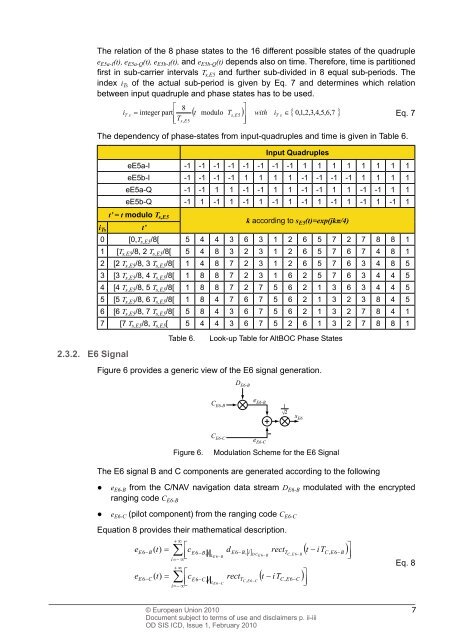
Figure 6 provides a generic view of the E6 signal generation.<br />
C E6-B<br />
C E6-C<br />
D E6-B<br />
e E6-B<br />
e E6-C<br />
1<br />
� 2<br />
–<br />
Figure 6. Modulation Scheme for the E6 Signal<br />
The E6 signal B and C components are generated according to the following<br />
● e E6-B from the C/NAV navigation data stream D E6-B modulated with the encrypted<br />
ranging code C E6-B<br />
● e E6-C (pilot component) from the ranging code C E6-C<br />
Equation 8 provides their mathematical description.<br />
e<br />
e<br />
E6�<br />
B<br />
E6�C<br />
( t)<br />
�<br />
( t)<br />
�<br />
� �<br />
�<br />
i��<br />
�<br />
� �<br />
�<br />
i��<br />
�<br />
�c ��<br />
E6�C<br />
, i rectT<br />
�<br />
L<br />
C , E 6�C<br />
E 6�C<br />
© European Union 2010<br />
Document subject to terms of use and disclaimers p. ii-iii<br />
OD <strong>SIS</strong> <strong>ICD</strong>, Issue 1, February 2010<br />
s E6<br />
�c ��<br />
E6�<br />
B,<br />
i d E6�<br />
B<br />
�<br />
L<br />
D C �<br />
, 6�<br />
6�<br />
E 6 B C E B<br />
E B<br />
, �� i rectT<br />
�tiTC, E6�<br />
B �<br />
�tiT� C,<br />
E6�C<br />
�<br />
��<br />
�<br />
��<br />
Eq. 8<br />
7