Galileo OS SIS ICD.indd - GSA - Europa
Galileo OS SIS ICD.indd - GSA - Europa
Galileo OS SIS ICD.indd - GSA - Europa

Create successful ePaper yourself
Turn your PDF publications into a flip-book with our unique Google optimized e-Paper software.
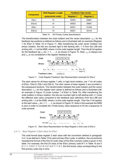
Component<br />
Shift Register Length<br />
(polynomial order)<br />
14 © European Union 2010<br />
Document subject to terms of use and disclaimers p. ii-iii<br />
OD <strong>SIS</strong> <strong>ICD</strong>, Issue 1, February 2010<br />
Feedback Taps (octal)<br />
Register 1 Register 2<br />
E5a-I 14 40503 50661<br />
E5a-Q 14 40503 50661<br />
E5b-I 14 64021 51445<br />
E5b-Q 14 64021 43143<br />
Table 14. E5 Primary Codes Specifi cations<br />
The transformation between the octal notation and the vector description {a i,j} for the<br />
feedback tap positions is defi ned as follows and is illustrated with an example (Register<br />
1 for E5a-I in Table 14) in Figure 11. After transferring the octal vector notation into<br />
binary notation, the bits are counted right to left starting with j = 0 from the LSB and<br />
ending with j = R at the MSB, where R is the code register length. Then the jth bit applies<br />
for the feedback tap a i,j for j = 1, …, R, as shown in Figure 10. Note, a i,R is always one<br />
and a i,0 is not considered in the register feedback tap.<br />
Figure 11. Code Register Feedback Taps Representation (example for E5a-I)<br />
The start values for all base register 1 cells, in logic level notation, are ‘1’ for all codes<br />
of E5a-I, E5a-Q, E5b-I and E5b-Q. The start values of base register 2 are provided in<br />
the subsequent sections. The transformation between the octal notation and the vector<br />
description {s i,j} for the register start values is defi ned as follows and is illustrated with<br />
an example in Figure 12 (code number 1 of E5a-I in Table 15). After transferring the<br />
octal notation in binary notation, the bits are counted right to left starting with j=1 (note<br />
the different start value compared to the feedback taps defi nition) from the LSB and<br />
ending with j=R at the MSB, where R is the code register length. Then the j th bit applies<br />
to the start value s i,j for j = 1, …, R, as shown in Figure 10. Note in this example the MSB<br />
is zero in order to complete the 14-bits binary value sequence to fi t into a sequence of<br />
octal symbols.<br />
Figure 12. Start Value Representation for Base Register 2 (fi rst code of E5a-I)<br />
3.4.1.1. Base Register 2 Start Value for E5a-I<br />
The octal format base register 2 start value with the convention defi ned in paragraph<br />
3.4.1 is as defi ned in Table 15 for each primary E5a-I code. In addition, the conventional<br />
hexadecimal format of the fi rst 24 code chips of the E5a-I primary codes is given in the<br />
table. For example, the fi rst 24 chips of the E5a-I primary code N°1 in Table 15 are 0<br />
0 1 1 1 1 0 0 1 1 1 0 1 0 1 0 1 0 0 1 1 1 0 1, the fi rst binary value corresponding to the<br />
fi rst primary code chip in time.