Download - Eurotherm Ltda
Download - Eurotherm Ltda
Download - Eurotherm Ltda

You also want an ePaper? Increase the reach of your titles
YUMPU automatically turns print PDFs into web optimized ePapers that Google loves.
ContentsiToolsChapter 4To Customise The DisplayTo Display Parameters Of Two Or More InstrumentsStoring Parameters In RecipeTo Open the Watch/Recipe WindowTo Build A RecipeTo Remove A Parameter From A ListTo Save The Current RecipeTo Open A New RecipeTo Open An Existing RecipeTo Enter A Parameter ValueData SetsTo Add A Data SetTo Delete A Data SetTo Copy And Paste Data SetsTo Rename A Data SetTo Enter The Current Values From The ControllerTo <strong>Download</strong> A Recipe Into An InstrumentQuick Tour 2 Instrument Configuration And CloningTo Configure an InstrumentTo Set Access LevelExample: To Configure An Alarm Type FromParameter ListsExample: To Set The Alarm Trip LevelCloningTo Create A Clone File From A ConnectedInstrumentTo Clone An Instrument From A FileTo Edit a Clone FileTo Clone from a Simulated Instrument3.5.63.63.73.83.8.13.8.23.8.33.8.43.8.53.8.63.8.73.93.9.13.9.23.9.33.9.43.9.53.9.64.14.1.14.1.24.1.34.1.44-24.2.14.2.24.2.34.2.4Chapter 5 2500 DIN Rail Controller IntroductionWhat Is The 2500 DIN Rail ControllerTo Connect A Single 2500 Controller To A PCTo Connect More Than One 2500 To A PCTo Set The Address SwitchBaud RateStarting and Exiting iToolsTo Start iToolsTo Exit iToolsAutodetectionTo Open Panel Views Of Instruments55.15.25.35.45.55.65.6.15.6.25.75.8ii User Handbook Part Number HA026179 Issue 2.0 Oct-99 Applies to Version 2.09
iToolsContentsChapter 6Chapter 7Instrument ParametersTo Display Instrument ParametersTo Select A Different List Of ParametersTo Display The Device BrowserTo Select A Different List Of Parameters Using TheDevice BrowserTo Change Parameter ValuesExample: To Set Baud Rateto Edit ParametersStoring Parameters In RecipeTo Open the Watch/Recipe WindowTo Build A RecipeTo Remove A Parameter From A ListTo Save The Current RecipeTo Open A New RecipeTo Open An Existing RecipeTo Enter A Parameter ValueData SetsTo Add A Data SetTo Delete A Data SetTo Copy And Paste Data SetsTo Rename A Data SetTo Enter The Current Values From The ControllerTo <strong>Download</strong> A Recipe Into An InstrumentQuick Tour 3 Configuration of I/O ModulesTo Set Access LevelI/O Module TypesTo Define I/O Module TypesChannel TypesTo Define Channel TypeChannel Types For Each ModuleInput LinearisationParameter Availability SettingsTo Select Parameter AvailabilityFailure To Write A ValueTo Set Up Other I/O ParametersExampleQuick Tour 4 User WiringExample Process Block DiagramThe Wiring EditorTo Open The Wiring EditorUser Values5.95.9.15.9.25.9.35.9.45.9.55.9.65.9.75.105.10.15.10.25.10.35.10.45.10.55.10.65.10.75.115.11.15.11.25.11.35.11.45.11.55.11.66.16.26.36.3.16.46.4.16.4.26.4.36.56.5.16.66.76.7.17.17.27.37.3.17.4User Handbook Part Number HA026179 Issue 2.0 Oct-99 Applies to Version 2.09 iii
ContentsiToolsTo Set Up A User ValueTo Enter Text Into The Comment FieldAnalogue CalculationsExample: To Produce An Analogue CalculationBlockLogic (Digital) CalculationsExample: To Produce A Logic Calculation BlockOutput Behaviour in Error SituationsWireable ParametersWiring Example: To Wire A Simple Single LoopControllerTo Disconnect A Wiring ConnectionWiring Example: Relative HumidityWireable Parameters Using The Analogue Or LogicCalculation TabsUser Wiring Using The Wireable Parameters TabTo Save ConfigurationsWireable Parameter Tables7.4.17.4.27.57.5.17.67.6.17.77.87.8.17.8.27.8.37.97.107.117.12Chapter 8 Modbus Addresses 8Appendix AAlternative Wiring MethodsWiring Using The Parameter ListsTo Wire IO Module 01 Output To Loop 1 PV InputTo Wire Control Loop 1 Output To Module 03 InputAA.1A.1.1A.1.2Appendix B The Menu Bar BAppendix C List of Related Handbooks CAppendix D Glossary of Terms DAppendix E Ordering Code EAppendix F <strong>Eurotherm</strong> Office Addresses Fiv User Handbook Part Number HA026179Issue 2.0 Oct-99 Applies to Version 2.09
iToolsContentsList of FiguresFigureGeneral View Of The iTools Window 1-1Connecting A Single InstrumentConnecting Up To 32 Instruments2-12-2The iTools Start Up WindowInstrument ViewsParameter List HeadingParameter ListsChanging Parameter ValuesCustomising The DisplayThe Watch/Recipe WindowExample of a Recipe3-13-23-33-43-53-63-73-8Selecting a Parameter ListSmall Browser WindowSelecting a ParameterConfiguring a Parameter TypeAlarm ParametersChanging Alarm ValueInstrument CloningEditing A Clone FileNew Clone File Dialog BoxSimulated Instrument Produced From A New Clone File4-14-24-34-44-54-64-74-84-94-10General View Of The 2500 DIN Rail ControllerConnection Between IOC And PC Using The Comms PortConnection of Multple 2500 ControllersThe Modbus Address SwitchThe Profibus Address SwitchParameter List HeadingChanging Parameter ValuesThe Watch/Recipe WindowExample of a recipe5-15-25-35-45-55-65-75-85-9User Handbook Part Number HA026179 Issue 2.0 Oct-99 Applies to Version 2.09 v
ContentsiToolsDefining A Module TypeDefining Channel Type6-16-2Examples of Analogue and Digital FunctionsExample of Wiring Parameters to a Function BlockAn Example of a Process Block DiagramThe Wiring EditorUser Values TabAnalogue Calculation TabAnalogue Calculation Block (Highest Wins)Logic Calculation TabLogic Calculation Block (Input1 < Input2)Sample & HoldThe Wireable Parameters TabBlock Diagram of PID Control Loop - Input Module ConnectionBlock Diagram of PID Control Loop - Output Module ConnectionRelative Humidity InputWireable ParametersPID Control Loop Block DiagramWiring From The Wireable Parameters Tab7-17-27-37-47-57-67-77-87-97-107-117-127-137-147-157-167-17PID Control Loop Block DiagramLocating The Modbus Address of the Parameter to be Wired FromTyping the Modbus Address into the Source ValueA-1A-2A-3vi User Handbook Part Number HA026179Issue 2.0 Oct-99 Applies to Version 2.09
iToolsAddendumA. ADDENDUM (SOFTWARE VERSION 2.09)............ 3a.a. Contents ...................................................................................................3a.b. iTools Editions .........................................................................................3a.b.1. iTools Demo Edition.............................................................................3a.b.2. iTools Standard Edition ........................................................................3a.b.3. iTools Open Edition..............................................................................3a.c. Installing iTools .......................................................................................4a.c.1. Product Key ..........................................................................................4a.c.2. System Requirements............................................................................4a.c.3. DCOM ..................................................................................................4a.c.4. Windows Common Controls Library (COMCTL32.DLL) ...................4a.d. Devices Supported...................................................................................5a.e. Changes since Version 1..........................................................................5a.e.1. iTools Supplied in Three Editions ........................................................5a.e.2. Configuration Station............................................................................5a.e.3. Toolbar Changes ...................................................................................6a.e.4. iTools Report Wizard............................................................................6a.e.5. Parameter Find Facility.........................................................................6a.e.6. Custom Linearisation Files....................................................................6a.e.7. OPC Scope............................................................................................7a.e.8. <strong>Eurotherm</strong> Project Studio Integration ...................................................7a.e.9. Internationalisation................................................................................7a.e.10. User Wiring renamed to Toolkit Blocks...........................................7a.e.11. Serial Ports used by iTools ...............................................................7a.e.12. Warning when using Unsupported Devices......................................7a.e.13. Visibility of OPC Server...................................................................8a.e.14. OLE for Process Control (OPC).......................................................8a.f. OPC Servers ............................................................................................8a.g. OPC Clients .............................................................................................8a.g.1. Possible Problems with this Release .....................................................8User Handbook. Part No HA026179 Issue 2.0 Oct-99 a-1
AddendumiToolsa. Addendum (Software Version 2.09)A.A. CONTENTS• iTools Editions• Installing iTools• Devices Supported• Changes since Version 1• Possible Problems with this ReleaseA.B. ITOOLS EDITIONSiTools is now available in two different 'Editions' according to the level of functionalityrequired: iTools Standard Edition and iTools Open Edition. A third version, iTools DemoEdition, is provided for evaluation only.It is possible to upgrade from iTools Demo Edition to either Standard or Open Edition bypurchasing a new Product Key from <strong>Eurotherm</strong>. Similarly, iTools Standard Edition may beupgraded to iTools Open Edition in this way.a.b.1. iTools Demo EditioniTools Demo Edition may be made available for evaluation purposes only.The following functionality is restricted in this edition:Modbus communications to devices is limited to 30 minutes;no cloning or download functionality is available;printing of reports from the iTools Report Wizard is not permitted.a.b.2. iTools Standard EditioniTools Standard Edition offers the full iTools functionality for configuration andcommissioning of <strong>Eurotherm</strong> devices.Access to the Modbus OPC Server from 3rd-party OPC clients is limited to 30 minutes, as isaccess to 3rd-party OPC servers from the OPC Scope utility. For unlimited access to OLE forProcess Control (OPC) functionality, iTools Open Edition is required.a.b.3. iTools Open EditioniTools Open Edition offers all the features of iTools Standard Edition, as well as providinginteroperability with any software that is compliant with OLE for Process Control (OPC), theindustry standard for data access to real-time devices.In addition to the functionality offered by iTools Standard Edition, the Open Edition allows:unlimted access to the Modbus OPC Server from 3rd-party OPC client applications,including the majority of SCADA software;unlimited access from the OPC Scope utility to 3rd-party OPC servers.a-2 User Handbook. Part No HA026179 Issue 2.0 Oct-99
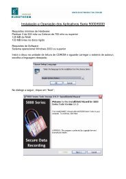
iToolsAddendum<strong>Eurotherm</strong> Controls Ltd is an OPC Foundation member.A.C. INSTALLING ITOOLSiTools is supplied on either CD-ROM or floppy disks.Installing from CD-ROMOn most computers, the CD-ROM version of iTools will start automatically as soon as it isinserted into the CD-ROM drive. If it does not auto-start, you should run the Install programfrom the CD's root folder.Installing from Floppy DiskRun the Setup program from the floppy disk labelled DISK 1. You will be prompted to insertother disks as they are needed.a.c.1. Product KeyDuring installation, you will be asked to enter a Product Key. The Product Key is a 10-digitnumber, split into three sections, e.g. 012-345-6789. You will find this number on the outsideof the package containing your iTools media (CD or floppy disks). If you enter an incorrectProduct Key, iTools will install with only Demo Edition features available.A new Product Key may be entered after installation, by selecting 'Registration Information...'from the Help menu in iTools.a.c.2. System RequirementsiTools requires Windows 95, Windows 98, or Windows NT 4.0 (Service Pack 3 or later).Note: installation under Windows NT must be performed by a user havingAdministrator privileges.The minimum specification under Windows 95 or Windows 98 is a 486DX/2 66MHz with16Mb of RAM.The minimum specification under Windows NT 4.0 is a Pentium 90 with 24Mb of RAM.On all systems, a Pentium 133 with 32Mb of RAM is recommended for optimumperformance.20Mb of free disk space is required on all systems. Additional disk space is required to installthe separate Setpoint Program Editor, or the Adobe Acrobat reader (CD-ROM version ofiTools only).User Handbook. Part No HA026179 Issue 2.0 Oct-99 a-3
AddendumiToolsa.c.3. DCOMiTools relies on the presence of Distributed COM (DCOM), even when connection to aremote computer is not involved. DCOM is a standard feature of Windows NT 4.0 (or later)and Windows 98, but must be separately installed on Windows 95.On Windows 95, the iTools Setup program checks for the presence of the latest release ofDCOM for Windows 95. If it is not found, the DCOM for Windows 95 update will beautomatically installed.a.c.4. Windows Common Controls Library (COMCTL32.DLL)iTools was developed using a recent version of this library, which is also installed as part ofMicrosoft Internet Explorer 4 or later. For maximum reliability, the iTools Setup programchecks for the presence of the latest release of COMCTL32.DLL. If it is not found, theCommon Controls update from Microsoft will be automatically installed.A.D. DEVICES SUPPORTEDThe following devices and versions are fully supported (unless detailed separately) by iTools.Where a device is of the same type but a different version from those listed here, much of theiTools functionality may be expected to work correctly, but no support will be provided.2204, 2208, 2216Version 1.30 Cloning is not complete – ‘DigF’ parameters are not transferred or updated.2204e, 2208e, 2216eVersions 2.06, 3.022404, 2408, 2416Versions 3.01, 3.05, 3.06, A4.05 (also versions 3.51, 3.55, 3.56)2408iVersions 1.00, 1.01Versions 1.04, 1.06, 2.08, 2.09A.E. CHANGES SINCE VERSION 1This section identifies the major changes to iTools since Version 1. A large number of minorchanges have also been made to improve usability, performance and robustness; most of theseare listed in the 'Release Notes' section of the iTools help file.a.e.1. iTools Supplied in Three EditionsiTools Version 1 was supplied in one edition only. iTools Version 2 is available in twodifferent editions (Standard and Open) according to the level of functionality required. Athird, Demo, edition is available for evaluation purposes only.See iTools Editions (above) for more information.a-4 User Handbook. Part No HA026179 Issue 2.0 Oct-99
iToolsAddenduma.e.2. Configuration StationConnection to all 2200, 2200e, 2400 and 2408i devices is now possible via the Series 2000Configuration Station.To connect to a device through the configuration station, select 'Configuration StationConnect...' from the Device menu. To disconnect, simply Remove the device in the usualway, i.e. using the Remove toolbar button or by selecting Remove from the Device menu.Note: having connected to an instrument via the Configuration Station, the instrumentmust not be physically disconnected from its clip until its has been 'Removed' fromiTools.a.e.3. Toolbar ChangesiTools Version 2 provides two new toolbar buttons:Print - starts the new iTools Report Wizard (equivalent to File | Print...);Access - toggles the Access Level of the selected device between Operator and Configuration(similar to Device | Set Access Level).Also, the button which starts/stops the process of scanning for new devices has been renamedfor clarity. The button's caption now shows 'Start Scan' or 'Stop Scan' according to the actionwhich will result from pressing the button. When scanning is currently active, the status barshows the Modbus device address currently being scanned.a.e.4. iTools Report WizardThe iTools Report Wizard has been provided to allow device configurations and clone files tobe documented. The following facilities are provided:output of parameter lists in a tabular form similar to the iTools on-screen display;columns to be included in the report are selectable, as with the on-screen parameter lists;the user may select a subset of a device's lists for inclusion in the report;the report may optionally be annotated with information such as user's name and company,product name and number, and a description;support for two output formats: HTML or CSV; HTML reports are previewed on-screen andmay be printed immediately (where Microsoft Internet Explorer 4 or later is installed).The iTools Report Wizard is started using the 'Print' toolbar button, or by selecting 'Print...'from the File menu, or from a device's popup menu.a.e.5. Parameter Find FacilityThe more complex <strong>Eurotherm</strong> instruments contain several thousand parameters, divided intomany separate lists. To make navigation easier, iTools now permits parameter searches.Simply specify all or part of the name or description of the parameter you wish to locate, andiTools will list all matching parameters. You may also search for matching comments, incases where user-defined comments have already been supplied.The 'Find' facility is located in a tabbed view adjacent to the Browser on the left side of theiTools main window.a.e.6. Custom Linearisation FilesCustom Linearisation Files may now be downloaded to devices which support this facility.This is achieved by:User Handbook. Part No HA026179 Issue 2.0 Oct-99 a-5
AddendumiToolsselecting 'Load Values From File' from the File menu or a device's own popup menu (rightclickon a device faceplate to activate this);changing the file type to 'Custom Linearisation Files (*.mtb)' in the file dialog, and openingthe desired file.iTools ships with a library of pre-defined Linearisation files. By default, these are installedinto the 'Linearisations' sub-folder of the main iTools program folder (e.g.C:\Program Files\<strong>Eurotherm</strong>\iTools\linearizations).The 2500 device supports three separate custom Linearisation tables. When downloading,you will be prompted to select which of the three tables to write to.Note: the contents of custom Linearisation tables are NOT copied when devices arecloned.a.e.7. OPC ScopeiTools Version 1 included the OPC Explorer as an unsupported utility for device andapplication commissioning. This utility is now called OPC Scope, and is a fully supportedcomponent of iTools.OPC Scope allows parameters from any connected device to be monitored, plotted on asimple trend chart, or logged to file. This data logging capability supports output to CSV ortab-separated files. Both formats have been optimised for loading into Microsoft Excel andother spreadsheet applications.OPC Scope may be launched from within iTools (e.g. from the View menu), or else from the<strong>Eurotherm</strong> iTools program group on the Start menu. OPC Scope may also be launched fromthe toolbar of any Watch/Recipe view; in this case it will automatically be set up to show thesame set of parameters which had been configured in the Watch/Recipe window.a.e.8. <strong>Eurotherm</strong> Project Studio IntegrationiTools will take advantage of facilities in <strong>Eurotherm</strong> Project Studio 2000 (where installed) toautomate certain operations:A new <strong>Eurotherm</strong> iTools Clone file may be created using the Windows Explorer. When thisfile is opened, iTools will normally prompt the user for the type of instrument which thisclone file represents. However, if the folder containing the clone file corresponds to an iToolsdevice within <strong>Eurotherm</strong> Project Studio, then the clone file will automatically be set up forthat device type.Similarly, when the user selects 'Send To Device' for a clone file, iTools will indicate thecorrect target device in bold text, if the clone file's folder corresponds to a particular devicewithin <strong>Eurotherm</strong> Project Studio.Contact your local <strong>Eurotherm</strong> representative for more information about <strong>Eurotherm</strong> ProjectStudio 2000.a.e.9. InternationalisationiTools Version 1 was available as an English language application only. As of Version 2,iTools may be localised for non-English markets. As well as iTools and the OPC Scope,parameter descriptions for all devices may be translated. Please contact your local <strong>Eurotherm</strong>representative to find out whether iTools has been localised for your market.a-6 User Handbook. Part No HA026179 Issue 2.0 Oct-99
iToolsAddenduma.e.10. User Wiring renamed to Toolkit BlocksThis editor, for use with 2500 devices, has been renamed to reflect the provision of a Toolkitof Analog and Logic Calculation Blocks, as well as the ability to wire parameters point-topoint.a.e.11. Serial Ports used by iToolsDuring execution of the iTools Setup program, the user is asked to specify which of thecomputer's serial (COM) ports will be used by iTools. This selection may now be modifiedafter installation through a new 'iTools' applet in the Windows Control Panel. The ControlPanel may be found by opening the 'My Computer' icon, or by selecting 'Settings' on thecomputer's 'Start' menu.a.e.12. Warning when using Unsupported DevicesFor each supported device type, iTools supports a number of different device versions. Forexample, iTools supports most version 3.xx 2400 devices, but does not fully support version2.xx or version 1.xx 2400s. When using iTools with instrument versions which are not fullysupported, a small number of operations may not complete successfully; in particular, anumber of errors may be expected when cloning such devices.So that the user is fully aware whether particular devices are fully supported, iTools nowgenerates a warning message when adding a device for which full support is not provided. Insuch a case, the user proceeds at their own risk. If desired, this warning message may besuppressed by running iTools with the '/NoWarn' command line option.a.e.13. Visibility of OPC ServerThe Modbus OPC Server, responsible for all iTools device communications, is now madeinvisible by default. This is because there is normally no need for an iTools user to interactwith this program directly. In case this is desired, the server can be made visible by either:starting the Modbus OPC Server before starting iTools; the Modbus OPC Server is found onthe Start menu under Programs | <strong>Eurotherm</strong> iTools | Advanced Toolsselecting Options | Advanced | Show Server from the iTools main menua.e.14. OLE for Process Control (OPC)iTools Open Edition is required in order to use the following OPC functionality. iToolsDemo Edition and iTools Standard Edition may be used to evaluate these features for alimited period. See iTools Editions (above) for more information.All published OPC specifications are available from the OPC Foundation, which owns alltrademarks related to OPC.<strong>Eurotherm</strong> Controls Ltd is an OPC Foundation member.A.F. OPC SERVERSThe iTools Modbus OPC Server may be used as a general purpose OPC Data Access server,supporting all required features of the OPC Data Access Custom Interface Specification 1.0a.This OPC server is identified by the ProgID '<strong>Eurotherm</strong>.ModbusServer.1'.iTools also includes an OPC Automation server, supporting all required features of the OPCData Access Automation Interface Specification 2.0. This server would typically be used withUser Handbook. Part No HA026179 Issue 2.0 Oct-99 a-7
AddendumiToolsMicrosoft Visual Basic 5.0 or later, and is identified by the ProgID'<strong>Eurotherm</strong>.OPCAutomation.1'.A small demo application, developed with Visual Basic 5.0 and using the Automation server,is installed as part of iTools by default. It may be found in the 'examples' sub-folder of themain iTools program folder.A.G. OPC CLIENTSiTools OPC Scope is a general purpose OPC Data Access client program, supporting many ofthe features of OPC Data Access versions 1 and 2.a.g.1. Possible Problems with this ReleaseWe are aware of the following issues. Please notify us of any problems you may experiencewith this release of iTools.• With certain early versions of Windows 95, and depending on the computer'snetworking configuration, iTools may delay for several minutes during startup. Thisproblem may be rectified by obtaining an updated version of the Windows Socketslibrary (currently Winsock/DNS Upgrade 1.2 for PPTP) from Microsoft.• It is possible that iTools may exhibit display problems when used with a very smallnumber of types of graphics card: in particular, the toolbar icons may be corrupted. Thisis due to a well-known compatibility issue with some display driver software versions. Ifthis should occur, you will probably be able to resolve the problem by either:obtaining an updated version of the driver software,changing the colour depth setting of the driver (i.e. increasing or decreasing the numberof available colours in the colour palette), orreducing the graphics hardware acceleration; this is accessed from the Performance tabof the System applet in the Control Panel.• Cloning of DigF (Digital Function Mask) parameters of 2200 devices may not functioncorrectly. Where used, these parameters should be checked individually following eachclone operation.• It is not possible to change the accessibility of parameters and lists on 2200 and 2200edevices through iTools, as it is for 2400 devices. For example, parameters may not behidden or promoted.• The Remote Instrument Protocol functionality does not work with version 1.00 of the2408i indicator product. In other words, iTools faceplates for this type of instrument willnot show live values. This is due to a minor fault in the indicator itself.• With OPC Scope, trend charts may display incorrectly when using the Review mode tozoom in to a very high magnification.• Under certain circumstances, the Modbus OPC Server application (EuroMBus) mayimpede the opening of certain types of document from the Explorer (i.e. the Windows 95a-8 User Handbook. Part No HA026179 Issue 2.0 Oct-99
iToolsAddendumshell). In some cases, the document may take several seconds to open. In others, thedocument may not open at all and Explorer will appear to hang. In this case, closing theModbus OPC Server should bring Explorer back to life.• If any part of iTools should terminate with an error, it is possible that the Modbus OPCServer and other elements of iTools may still be in memory. This may prevent iToolsrunning successfully until the problem is resolved. If you suspect that this may havehappened, you should use a Task Manager or Process Viewer application to ensure thatneither EUROMBUS.EXE nor any application named ID*.EXE is still running.• When iTools is uninstalled, some files may be left behind. These should be removedmanually.User Handbook. Part No HA026179 Issue 2.0 Oct-99 a-9
AddendumiToolsa-10 User Handbook. Part No HA026179 Issue 2.0 Oct-99
iToolsIntroduction1. CHAPTER 1 INTRODUCTION............................................ 21.1. WELCOME..................................................................................................21.2. WHAT IS ITOOLS......................................................................................21.3. WHO USES ITOOLS ..................................................................................31.4. PC REQUIREMENTS.................................................................................31.5. ABOUT THIS MANUAL............................................................................3User Handbook. Part No HA026179 Issue 2.0 Oct-99 1-1
IntroductioniTools1. CHAPTER 1 Introduction1.1. WELCOMEToolbar showing icons for:New Clone, Open Clone, Save, Add Device, RemoveDevice, Scan, Open Parameter List, User WiringSelected device ishighlighted.Yellow display forreal instrument.White display forclone files.Clone file namePort: Com1Address: 1Controller:2408S/W V1.02‘Explorer’ style folders depict each page ofinstrument parametersParameter list showing the parameterdescription, the parameter address and thecurrent value.Figure 1-1: General View Of The iTools WindowWelcome to <strong>Eurotherm</strong> iTools, the Windows® based software package designed to configurecommunicating 2000 series instruments.1.2. WHAT IS ITOOLSiTools is a Windows® based software package designed to configure communicating 2200,2400 panel controllers and the 2500 DIN rail controllers. It will operate on personalcomputers running Windows® 95 or NT (NT versions 4 or later). It uses Modbus RTUcommunications via a serial port.iTools will scan the network on request, and identify any 2000 series instrument that isconnected to the network and has a valid Modbus address. Using <strong>Eurotherm</strong>’s unique‘Remote Interface Protocol’, iTools provides a replica of the front panel of the attachedinstrument. This replica can then be used by the operator, using mouse clicks to simulatepressing the buttons - hidden or promoted parameters will remain exactly as they are in theactual instrument. (If the instrument is a 2500 DIN Rail Controller, which does not have afront panel, a simulation of the instrument plug in modules is displayed). The faceplate is an1-2 User Handbook. Part No HA026179 Issue 2.0 Oct-99
iToolsIntroductionActiveX TM component which can be used within any ActiveX TM container application, such asVisual Basic forms.In addition to the instrument faceplate, all the parameters within the instrument are availablein a separate window. Each parameter list is shown as a folder, and by clicking on it, all theparameters in that list are displayed, together with their current value. Where applicable, theparameter lists follow the same order as the instrument faceplate.Copying the complete set of parameter values from the attached instrument to a file can bedone at the click of a button - this file can be ‘cloned’ onto a new instrument to provide aduplicate.iTools Modbus driver is a server application which will permit iTools themselves, as a client,to run on the same or any networked PC. It can also operate as an OPC TM server (OPC dataaccess version 1.08a) providing data links into other OPC compliant software. Connectioncan also be made through a remote modem.1.3. WHO USES ITOOLSThese tools are intended for use by anyone wishing to communicate with <strong>Eurotherm</strong> 2000series communicating instruments in the field, where simplicity of set up and use is of primeimportance. The tools will be used in the following scenarios:Creating, cloning (duplicating) and saving instrument configurations; creating programs.Commissioning. On line set up of one or more instruments during start up of a system.Creating application programs including user wiring1.4. PC REQUIREMENTSiTools will run on a personal computer (PC) with the following specification:PC with at least one free RS232 serial communications port, e.g. Com 1, runningWindows®95 or NT (version 4 or later).A minimum of 16Mb RAM (24Mb for NT) is recommendedA standard VGA (640x480) screen is adequate, but larger screens allow more parameters tobe displayed at once and give a better presentation of the data.About 10Mb of disc space is required.1.5. ABOUT THIS MANUALThis manual is constructed as a series of ‘Quick Tours’ which explains typical features ofiTools by working through a series of examples. It is intended that the user of iTools shoulduse the procedures explained for each example as a basis for developing his or her ownapplication.The earlier chapters explain iTools when used with the <strong>Eurotherm</strong> 2000 series of indicatorsand controllers and this is followed by the 2500 DIN Rail Controller.User Handbook. Part No HA026179 Issue 2.0 Oct-99 1-3
IntroductioniTools1-4 User Handbook. Part No HA026179 Issue 2.0 Oct-99
iToolsInstallation1. CHAPTER 2 INSTALLATION ............................................. 21.1. CABLING.....................................................................................................21.2. GROUNDING ..............................................................................................21.3. WIRING GENERAL ...................................................................................21.4. DISCRETE INSTRUMENTS .....................................................................31.4.1. Wiring RS232 .............................................................................................31.4.2.Wiring RS485 ..............................................................................................31.5. TO INSTALL ITOOLS SOFTWARE........................................................41.6. COMMS PORTS .........................................................................................41.7. STARTING AND EXITING ITOOLS.......................................................51.7.1. To start iTools.............................................................................................51.7.2. To exit iTools..............................................................................................51.8. TO ACCESS HELP .....................................................................................5User Handbook. Part No HA026179 Issue 2.0 Oct-99 2-1
InstallationiTools2. CHAPTER 2 Installation2.1. CABLINGThe 2-wire, RS485 standard will normally be used for communicating with series 2000instruments. This standard allows the following:1. Connection of multiple instruments2. The distance from instrument to PC up to 4000 feet up to baud rates of 100Kbaud.3. The environment is electrically noisyIf required, a single 2400 series instrument can be connected directly to the PC, usually toCOM1 or COM2, using the RS232 standard. Ensure that the 2400 has the correctcommunications modules fitted.A full description of the standards and wiring details is given in the relevant <strong>Eurotherm</strong>instrument handbooks. See Appendix C for related handbooks and their part numbers.An overview is reproduced as follows:2.2. GROUNDINGTo reduce interference from external electrical signals, ground the cable screen at a singleground point. There should not be multiple ground paths in a single cable run. When using a<strong>Eurotherm</strong> Controls KD485 Communications Adapter unit, do not connect the screen fromone side of the interface to the other. Rather, ground each of the cables separately at a localground point.2.3. WIRING GENERALRoute communications cables in separate trunking to power cables. Power cables are thoseconnecting power to instruments, relay or triac ac supplies and wiring associated withexternal switching devices such as contactors, relays or motor speed drives.Communication cables may be routed with control signal cables if these signal cables are notexposed to an interference source. Control signals are the analogue or logic inputs andanalogue or logic outputs of any control instrument. Multiple instruments must be ‘daisychained’, as shown in figure 2-2, avoiding parallel connections.Do not use redundant wires in the communications cable for other signals, and do not use thescreen as a substitute for the common connection.Ensure cable runs have sufficient slack to ensure that movement does not cause abrasion ofthe insulating sheath. Do not over tighten cable clamps to avoid accidental multiplegrounding of the screen conductors.Refer to ‘EMC Electromagnetic Compatibility’ guide <strong>Eurotherm</strong> part no. HA025464 forfurther information.2-2 User Handbook. Part No HA026179 Issue 2.0 Oct-99
iToolsInstallation2.4. DISCRETE INSTRUMENTS2.4.1. Wiring RS232PCTx Com Rx2200 &2400 seriesinstrumentTx Com RxFor 2200 & 2400 series controllers recommendedcable:CABLE/9PINPC/NOPLUG/232/3.0MFigure 2-1: Connecting a Single Instrument2.4.2. Wiring RS485PC220 ohmterminationresistoron the lastcontroller in thechainTx Com RxCom Rx TxTypeKD485converterTx- Com Rx+Tx Rx-RS485220 ohmterminationresistoron the Rx of theconverter unitTwisted pairsController 2HF (B+ Tx)HE (A+ Rx)ComController 1HF (B+ Tx)HE (A+ Rx)ComFigure 2-2: Connecting up to 32 InstrumentsUser Handbook. Part No HA026179 Issue 2.0 Oct-99 2-3
InstallationiTools2.5. TO INSTALL ITOOLS SOFTWARENote:If you are installing iTools and already have a version of iTools on your system, it isbest to ‘uninstall’ the older version rather than just writing over it. To do so selectSettings from the Windows Start Bar. Click Control Panel and double click onAdd/Remove Programs. Select iTools and click Add/Remove. Confirm thedeletion by clicking Yes when prompted. Then click OK through two consecutivedialog boxes. The existing version of iTools is uninstalled, and you are ready toinstall this version.Installation of a new version of iTools should not affect clone files which have alreadybeen produced. Clone file simulations, however, which are supplied as part of theupgrade will be overwritten. It is, therefore, advisable to make a backup of all clonefiles prior to installation of a new version of iTools.It is also recommended that all other Windows programs are closed down duringinstallation.The iTools package consists of a set of 3.5 inch disks.• Insert the disc labelled disc 1 into the diskette drive of the PC, - this will usually be drivea.• From the Windows Start Bar, click Run• Type a:\SETUPThe set up program prompts you through the installation process.Follow the instructions on the screen.The drive on which iTools will normally be installed is drive C: but an alternative drive maybe chosen.The directory where iTools will normally be installed is \Program Files\<strong>Eurotherm</strong>\iTools.Other locations are allowed and may be chosen using usual Windows methods.Note: Any version of iTools already installed in this directory will be overwritten unless adifferent directory is specified.2.6. COMMS PORTSiTools will support up to eight comms ports. During installation you will have been asked tospecify which comms ports your instruments will be connected to. ITools automaticallyscans for instruments connected to these ports (see paragraph 3.4 ‘Autodetection’ )2-4 User Handbook. Part No HA026179 Issue 2.0 Oct-99
iToolsInstallation2.7. STARTING AND EXITING ITOOLS2.7.1. To start iToolsiTools may be started in either of the following ways:I. DirectlyA. From the Windows Start Bar, click Programs.B. Select <strong>Eurotherm</strong> iToolsC. Click iToolsII.IndirectlyA. Open an instrument clone file, recognisable by its .uic file extension,directly from Windows Explorer.2.7.2. To exit iTools1. Click Exit from the iTools File menu,2.8. TO ACCESS HELP1. From the Help menu, select Contents. The help Contents tab appears; select a topic oruse the Index or Find tabsUser Handbook. Part No HA026179 Issue 2.0 Oct-99 2-5
InstallationiTools2-6 User Handbook. Part No HA026179 Issue 2.0 Oct-99
iTools Quick Tour 13. CHAPTER 3 QUICK TOUR 1 ............................................. 23.1. THE BASICS................................................................................................23.2. STARTING AND EXITING ITOOLS.......................................................33.2.1. To start iTools.............................................................................................33.2.2. To exit iTools..............................................................................................33.3. TO OPEN A REPLICA (OR VIEW) OF INSTRUMENTS.....................33.4. AUTODETECTION ....................................................................................43.4.1. Baud Rates ..................................................................................................43.4.2. To Operate An Instrument...........................................................................53.5. INSTRUMENT PARAMETERS................................................................63.5.1. To Display Instrument Parameters ..............................................................63.5.2. To Select a Different List of Parameters .....................................................63.5.3. To Display the Device Browser ..................................................................73.5.4. To Select a Different List of Parameters using the Device Browser ...........73.5.5. To Change Parameter Values......................................................................83.5.6. To Edit Parameters......................................................................................93.6. TO CUSTOMISE THE DISPLAY ...........................................................103.7. TO DISPLAY PARAMETERS OF TWO OR MORE INSTRUMENTS113.8. STORING PARAMETERS IN RECIPE .................................................123.8.1. To Open the Watch/Recipe Window ........................................................123.8.2. To Build a Recipe .....................................................................................123.8.3. To Remove a Parameter From the List......................................................133.8.4. To Save The Current Recipe.....................................................................133.8.5. To Open A New Recipe ............................................................................133.8.6. To Open An Existing Recipe ....................................................................133.8.7. To Enter A Parameter Value.....................................................................133.9. DATA SETS................................................................................................143.9.1. To Add A Data Set....................................................................................143.9.2. To Delete A Data Set ................................................................................143.9.3. To Copy And Paste Data Sets ...................................................................143.9.4. To Rename A Data Set..............................................................................143.9.5. To Enter The Current Values From The Controller ..................................153.9.6. To <strong>Download</strong> A Recipe Into An Instrument .............................................15User Handbook. Part No HA026179 Issue 2.0 Oct-99 3-1
Quick Tour 1iTools3. CHAPTER 3 Quick Tour 13.1. THE BASICSThis quick tour is a step by step tutorial in which you run iTools, scan for all connectedinstruments and operate connected instruments from the screen.Note: This chapter shows 2200 and 2400 series instruments only, but the principles applyequally for other 2000 series instruments such as 2500DIN Rail Controller.Note: This quick tour assumes that you have a basic understanding of Windows 95, or NTsystem.About this Quick Tour◊◊◊◊◊◊◊◊◊◊◊Starting iToolsTo open views of instrumentsAuto-detectionBaud rateTo operate an instrumentInstrument parametersTo change parameter valuesTo edit parametersTo customise the displayTo display parameters of two or more instrumentsStoring parameters in recipe3-2 User Handbook. Part No HA026179 Issue 2.0 Oct-99
iTools Quick Tour 13.2. STARTING AND EXITING ITOOLS3.2.1. To start iToolsiTools may be started in either of the following ways:I. DirectlyA. From the Windows Start Bar, click Programs.B. Select <strong>Eurotherm</strong> iToolsC. Click iToolsII. IndirectlyA. Open an instrument clone file, recognisable by its .uic file extension,directly from Windows Explorer.3.2.2. To exit iTools1. Click Exit from the iTools File menu,On a new application, the iTools window appears as follows:Menu BarToolbarStatus BarFigure 3-1: The iTools Start Up Window3.3. TO OPEN A REPLICA (OR VIEW) OF INSTRUMENTSReplica views of instruments may be opened in either of the following ways:1. By enabling background scanning for new devices. This can be from the iTools mainmenu or toolbar2. By selecting the Add Devices command from the iTools menu or toolbar. This willdisplay a list of available devices (both real and simulated) to select fromThese methods are described further in the following pages.User Handbook. Part No HA026179 Issue 2.0 Oct-99 3-3
Quick Tour 1iTools3.4. AUTODETECTION1. Press the button. This will change to ScanningDuring the auto-detection process, iTools will search for up to 32 connected <strong>Eurotherm</strong>instruments. It will automatically check all instrument addresses and baud rates. (see alsoparagraph 3.4.1 ‘Baud Rates’).When instruments have been found, instrument views are automatically displayed in theiTools window (assuming Panel Views has been checked in the View menu). The displayedvalues are coloured yellow to indicate that these are physically connected instruments. Onceall instruments have been detected, stop iTools scanning by pressing the Scanning buttonwhich will change to Not Scanning.If no instruments are detected then no unit face-plates will be presented.AUTOMANRUNHOLDClick here and drag to changethe size of the instrument viewarea3.4.1. Baud RatesFigure 3-2: Instrument ViewsDuring the autodetection process, iTools will automatically scan for instruments connected tothe comms ports. It will assume the baud rate of the first instrument detected - i.e. the onewith the lowest address. Any subsequent instrument which has been set to a different baudrate will show in iTools as a ‘Comms Error’. Baud rates of 1200, 2400, 4800, 9600 and19,200 can be set in the 2200 and 2400 series instruments - the factory default being 9600.Baud rate is set in the Configuration Mode of the instrument - see the relevant user handbooklisted in Appendix C.3-4 User Handbook. Part No HA026179 Issue 2.0 Oct-99
iTools Quick Tour 13.4.2. To Operate An InstrumentInstruments can be operated directly from the instrument views on the PC screen in exactlythe same way as the instrument itself. A full description of the operation of an instrument isgiven in the relevant Installation and Operation Manual for that instrument, (see Appendix C,‘List of Related Instrument Handbooks’). A summary of operation is given below:-1. Use the mouse to point the cursor at the button on the selected instrument on the screen.Click the left mouse button to operate the screen ‘button’ icon.2. To Change Setpoint. Point and click on the or button3. To View ListPoint and click on the buttonHeadingsSuccessive clicks will scroll through Instrument ListHeadings4. To View Parameters Having selected the desired list heading, point and click thebutton to select the desired parameter from the list5. To Change aPoint and click on the or buttonParameter Value6. To SelectPoint and click the AUTO MAN buttonAuto/Manual7. To Select Run/Hold Point and click the RUN HOLD buttonUser Handbook. Part No HA026179 Issue 2.0 Oct-99 3-5
Quick Tour 1iTools3.5. INSTRUMENT PARAMETERSInstrument parameters are settings in the instrument which you can change to suit the process.In 2200 and 2400 instruments they are grouped under List Headings according to thefunction they perform. The List Headings are the names of sub-folders found in the DeviceBrowser.3.5.1. To Display Instrument ParametersInstrument parameters may be displayed in three ways:1. Double click on the required instrument view (or the instrument name in the DeviceBrowser)2. Right click on the instrument view (or the instrument name in the Device Browser) andselect Parameter List from the pop up window3. Left click on the required instrument view. From the Toolbar click Device Views followed by Parameter ListA list of parameters are displayed which are grouped under a List Heading. This heading isdisplayed in the upper left corner of the ‘parameters’ window, see Figure 3-3.Figure 3-3: Parameter List Heading3.5.2. To Select a Different List of Parameters1. In the Parameter List window, click on the folder . This opens a small browserwindow.The browser contains a number of folders, such as:• Operator• Programmer• Access Edit Mode• Config• Register• RIPThe names and number of folders is dependant onthe particular instrument type. This list applies to2400 seriesEach of these folders contain sub-folders. The lists of parameters are found in each ofthese sub-folders. A full list of parameters is given in the relevant instrument handbook.See Appendix C ‘List of Related Instrument Handbooks’..2. Open the required folder by double clicking on the folder (or folder name), or clickagainst the folder.3. Open the required sub-folder by double clicking on the folder (or folder name), or clickOK.3-6 User Handbook. Part No HA026179 Issue 2.0 Oct-99
iTools Quick Tour 13.5.3. To Display the Device BrowserFrom the View menu select Device Browser, (see also ‘To Customise the Display’ paragraph3-6). This will split the lower part of the iTools display into two sections - see Figure 3-4.1. The right hand section will show the selected parameter list, as selected above.2. The left hand section will show the Device Browser. This will open on the foldercontaining the selected Parameter List Heading.3.5.4. To Select a Different List of Parameters using the DeviceBrowser1. Single click on a folder or name of the list heading. This has the same effect as the smallbrowser window in 3.5.2 above.2. Double clicking the folder, or pressing , will open a list of parameter tags. These tagsmay be used to copy parameters when they are ‘wired’ between I/O modules and functionblocks in controllers such as 2500 and 2600. See Chapter 7 - User Wiring.Selected instrumentDevice Browser showingthe name of theParameter List HeadingParameter List associatedwith the chosen list headingClick on a folder to choosea new set of parametersRead only parameters are shown in blueRead/Write parameters are shown in blackFigure 3-4: Parameter ListsUser Handbook. Part No HA026179 Issue 2.0 Oct-99 3-7
Quick Tour 1iTools3.5.5. To Change Parameter ValuesParameters can be Read only or Read/Write. Read only parameters are shown in blue andread/write parameters are shown in black in the parameter lists. Only Read/Write parametervalues can be changed. Parameter visibility also depends upon the access level of theinstrument (to change Access Level see Paragraph 4.1.2).and some parameters can only bechanged within their set limits, eg SP (setpoint) whichhas high and low limits attached.Parameter values can be Analogue Values or Enumerated Values. With analogue valuesthe integer value can be adjusted between maximum and minimum limits. With enumeratedvalues a selection of states can be made.There are three ways to change parameter values:-1. From the Parameter List window double click on the selected parameter2. From the Parameter List window right click on the selected parameter and from the popup menu select Edit Parameter Value3. From the menu bar select Parameter List and from the pop up menu select EditParameter ValueA pop up window will appear, see Figure 3-5.4. If the parameter is an analogue value, type in thenew value and Click OK or ApplyCare should be taken to ensure that parameters are notset to values which may interfere with the expectedoperation of the process. See notes at the end ofsection 5.9.5. If the parameter is an enumerated value, such as‘Auto/Manual’, select the condition from the pulldownlist.. Enumerated values can have more thantwo selections.Note:OK will cancel the dialog boxApply will retain the dialog boxFigure 3-5: Changing Parameter ValuesNote: The parameter lists make available all parameters (including those hidden in thefaceplate view) which can be accessed over comms. This is a much longer list than isavailable by operating the instrument via the face-plate menu system. The complete list ofavailable parameters and their MODBUS addresses are given in the Series 2000Communications Handbook, part no. HA 026230. These additional parameters may berequired if the instrument is integrated into a larger system, See ‘User Wiring’ Chapter 7You are now able to operate any <strong>Eurotherm</strong> 2000 series communicating instrument from thescreen.3-8 User Handbook. Part No HA026179 Issue 2.0 Oct-99
iTools Quick Tour 13.5.6. To Edit ParametersIn addition to changing values of parameters, the properties of parameters can be changed.There are three ways to do this:-1. From the Parameter List window right click on the parameterA pop up menu will appear. This gives the following choices:-a) Edit Parameter Value - allows parameter values to be changed - see section 3.5.5.b) Edit Parameter Comment - allows a comment to be added against the parameterc) Parameter Properties - allows the properties of the parameter to be viewedd) Copy - allows the parameter to be copied to the clipboard for use in User Wiring(see Chapter 7) or Watch/Recipe windows (see paragraph 3.8).e) Refresh - allows the parameter list to be updatedf) Columns - allows columns to be added to or deleted from the parameter listdisplay, as follows:-I. Description - the full name of the parameterII. Address - the MODBUS address numberIII. Limits - the high and low limits which are applied to the parameterIV. Wireable - the device that the parameter is wired to. This is not applicable to2200 and 2400 series instruments. See Chapter 7 for more information.V. Comment - allows a comment to be displayed against each parameter2. From the Menu Bar, left click on the Parameter List menuA pop up window will appear. This gives the following choices:-a) Edit Parameter Value - allows parameter values to be changed - see section 3.5.5.b) Edit Parameter Comment - allows a comment to be added against the parameterc) Parameter Properties - allows the properties of the parameter to be viewedd) Browse - displays a small browse windowe) Refresh - allows the parameter list to be updatedf) Columns - allows columns to be added to or deleted from the parameter listdisplay, as follows:-I. Description - the full name of the parameterII. Address - the MODBUS address numberIII. Limits - the high and low limits which are applied to the parameterIV. Wireable - the device that the parameter is wired to. This is not applicable to2200 and 2400 series instruments. See Chapter 7 for more information.V. Comment - allows a comment to be displayed against each parameter3. From the Device Browser, double click on the folder or parameter list name, ORclick against the parameter list name. This opens a list of parameter tags.Right click on the parameter tag. A small window gives the following choices:-a) Edit - allows parameter values to be changed - see section 3.5.5.b) Properties - allows the properties of the parameter to be viewedc) Copy - allows the parameter to be copied to a wireable parameterUser Handbook. Part No HA026179 Issue 2.0 Oct-99 3-9
Quick Tour 1iTools3.6. TO CUSTOMISE THE DISPLAYThe display can be customised as follows:From the View menu:9 Toolbar to select the toolbar9 Status Bar to select the status bar9 Panel Views to select instrument views9 Device Browser to select device browser and parameter list headingsFigures 3-1 and 3-2 have been shown with the above views selected. De-select any area ofthe display by clicking the 9. Change the size of an area by clicking the area boundary anddragging the boundary to a new position, (see Figure 3-2).Note: Throughout the remainder of this manual, unless otherwise stated, it will be assumedthat Toolbar, Status Bar and Panel Views are selected.From the Options menu9 Show Device Names To display the name of the clone file or device onthe instrument view9 Show Labels on Toolbar To display the names against toolbar icons9 Active Window Follows Device used when two or more clone files are open.The active parameter list corresponds to theScalingUpdate RatesDecimal PlacesSend Command To ServerClear Most Recently Used ListsSave Settings NowSave Settings on Exitinstrument selectedUsed when a mix of instrument sizes are displayedon the same screen. Instrument views may bedisplayed to scale or changed in size relative to eachotherBy default :’Panel Views’ are updated every 1500ms‘When No Key Pressed’ and every 100ms ‘WhenKey Pressed’.Parameter Lists are updated every 2000msIt is recommended that these settings are onlychanged in very special circumstances, for examplein networked systemsValue will be rounded to the number of decimalplacesTo send a command to a server in networkedsystemsClear the most recently used files from the File andDevice menusSave the customised screen settings when selectedSave the customised screen settings when iTools isclosed3-10 User Handbook. Part No HA026179 Issue 2.0 Oct-99
iTools Quick Tour 13.7. TO DISPLAY PARAMETERS OF TWO OR MOREINSTRUMENTS1. Choose an instrument. From the Toolbar click Device Views followed by ParameterList.2. Choose a second instrument. From the Toolbar click Device Views followed byParameter List.3. Repeat 2 and 3 for further instrument parameter lists4. Select Window to format the display. The choices are:-a) Tile Horizontally b) Arranges Parameter Lists horizontallya) Tile Vertically b) Arranges Parameter Lists verticallya) Cascade b) Arranges Parameter Lists in cascadeNote: The display below is with the:Device Browser de-selected and Window - Tile Vertically.Menu BarToolbarPanelViewsStatus BarFigure 3-6: Customising the DisplayUser Handbook. Part No HA026179 Issue 2.0 Oct-99 3-11
Quick Tour 1iTools3.8. STORING PARAMETERS IN RECIPEA particular process may be required to run a range of products which require differentsettings to be entered into the control system. If these are held in a series of recipes a rapidand accurate way of setting up the process can be achieved.A recipe, therefore, is a customised set of parameters which can be given different valueswhich are stored in data sets. It can be named - say, with the reference of the batch to whichit applies, and downloaded into the control system.This section describes how to configure, store, and download recipes into the controllers.3.8.1. To Open the Watch/Recipe Window1. From the View menu select Watch/Recipe2. A Watch/Recipe window is displayed, see Figure 3-73.8.2. To Build a RecipeFigure 3-7: The Watch/Recipe WindowParameters of your choice may be placed into the recipe window in four ways, as follows:1. From the Device Browser, locate the required parameter from the file structure asdescribed in section 3.5.4a) Drag and drop the parameter into the Recipe windowb) Repeat the above for all required parameters2. From the menu bar of the ‘Watch/Recipe’ window click ‘Browser for parameterto add to recipe’.a) From the small browser window select the parameter and either double click theparameter or click OK3. From the main menu bar click ‘Watch/Recipe’a) Click ‘Add Parameter’b) From the small browser window select the parameter and either double click theparameter or click OK4. Right click in the Watch/Recipe window and click ‘Add Parameter’3-12 User Handbook. Part No HA026179 Issue 2.0 Oct-99
iTools Quick Tour 13.8.3. To Remove a Parameter From the List1. Click to highlight the parameter which is no longer required in recipe2. From the menu bar of the ‘Watch/Recipe’ window, click ‘Remove the selectedparameter from this recipe’ORPress Ctrl+DelORRight click on the selected parameter and click‘Delete Parameter’3.8.4. To Save The Current Recipe1. From the menu bar of the ‘Watch/Recipe’ window, click ‘Save’2. For a new recipe the Save As dialog box will appear. Save the recipe in the appropriatedirectory with an appropriate file name3.8.5. To Open A New Recipe1. From the menu bar of the ‘Watch/Recipe’ window, click ‘Create a newwatch/recipe listParameters may be added to and removed from this list as described in 3.8.2 and 3.8.3, andthe new recipe saved as described in 3.8.43.8.6. To Open An Existing Recipe1. From the menu bar of the ‘Watch/Recipe’ window, click ‘Open an existingwatch/recipe file’2. From the file control menu select the required file and click OK or double click on thefile name3.8.7. To Enter A Parameter Value1. In the Watch/Recipe window, either double click on the parameterOR2. Right click on the parameter and select ‘Edit Parameter Value’3. From the dialog box type in the new value or if the parameter is enumerated select thenew state from the listNote:- If the message ‘Value rejected by device’ appears, check that the parameter isread/write. These are shown in black in the parameter lists. Parameters shown in blue areread only. Some parameters can only be written to under certain conditions, for example,when the instrument is in configuration mode.User Handbook. Part No HA026179 Issue 2.0 Oct-99 3-13
Quick Tour 1iTools3.9. DATA SETSData sets allow you to choose different sets of parameter values, in a given recipe, dependingupon the conditions required to run the process, eg, the type of batch to be run.Up to 32 data sets can be added. Data sets can be deleted, copied and pasted from one toanother or captured from the current running conditions in the instrument. These aredescribed in the following sections.3.9.1. To Add A Data Set1. From the Watch/Recipe window click ‘Create a new empty data set’OR2. Right click in the area of the data set and click ‘New Data Set’3.9.2. To Delete A Data Set1. Select the data set to be deleted and, from the Watch/Recipe window, click ‘Deletethe selected data set’OR2. Right click on the data set to be deleted and click ‘Delete Data Set’3.9.3. To Copy And Paste Data SetsThis is useful if only a few parameters are changed from one data set to another.1. Right click in the data set to be copied2. From the pop up window click Copy Data Set3. Right click in the data set to be copied to4. From the pop up window click Paste Data SetA parameter can be edited by double clicking on the parameter and from the pop up windowenter the new value.3.9.4. To Rename A Data SetA new data set is given a default name, eg Data Set 1. A title of your choice can be given asfollows:-1. Right click the data set2. From the pop up window enter the required title using alpha-numeric characters.3-14 User Handbook. Part No HA026179 Issue 2.0 Oct-99
iTools Quick Tour 13.9.5. To Enter The Current Values From The ControllerIt is often convenient to ‘snapshot’ the current values of parameters in a controller into thecurrent recipe. This is useful, for example, when the process is running at its optimumsettings for the batch or job being processed.This may be done in two ways1. From the menu bar of the ‘Watch/Recipe’ window, click ‘Capture currentvalues into a data set’OR2. Right click in the section containing ‘Data Set’ and click ‘Snapshot Values’3. If more than one data set is displayed, right click in the data set in which you wish thecurrent values to be stored, and repeat 2 above4. If no data set is displayed or a new data set is required, right click in the area containingthe data set and click‘New Data Set’. OR from the Watch/Recipe menu bar click‘Create a new empty data set’3.9.6. To <strong>Download</strong> A Recipe Into An InstrumentThe parameter values stored in the data set of a recipe can be downloaded into an instrumentin two ways:-1. Click in the column containing the data set to be downloaded then click ‘<strong>Download</strong>the selected data set to the device’OR2. Right click in the column containing the data set to be downloaded, then click‘<strong>Download</strong> Values’Figure 3-8 shows an example of a recipe with data sets which may be configured using theabove procedures.Figure 3-8:Example of a RecipeUser Handbook. Part No HA026179 Issue 2.0 Oct-99 3-15
Quick Tour 1iTools3-16 User Handbook. Part No HA026179 Issue 2.0 Oct-99
iTools Quick Tour 24. CHAPTER 4 QUICK TOUR 2 ............................................. 24.1. INSTRUMENT CONFIGURATION AND CLONING............................24.1.1. To Configure an Instrument ........................................................................34.1.2. To Set Access Level....................................................................................34.1.3. Example: To Configure An Alarm Type from Parameter Lists..................34.1.4. Example: To Set the Alarm Trip Level ......................................................54.2. CLONING ....................................................................................................64.2.1. To Create a Clone File From a Connected Instrument................................74.2.2. To Clone an Instrument from a File ............................................................84.2.3. To Edit a Clone File....................................................................................94.2.4. To Clone From a Simulated Instrument ....................................................10User Handbook. Part No HA026179 Issue 2.0 Oct-99 4-1
Quick Tour 2iTools4. Chapter 4 QUICK TOUR 24.1. INSTRUMENT CONFIGURATION AND CLONINGThis quick tour is a step by step guide to configuring and setting up parameter values in<strong>Eurotherm</strong> 2000 series instruments. iTools allows instrument configuration details andcommissioning values to be saved to a file which can be copied (cloned) to other instrumentsof the same type.Note: This chapter shows 2200 and 2400 series instruments only, but the principles applyequally for other 2000 series instruments such as 2500DIN Rail Controller.Note: This quick tour assumes that you have completed Quick Tour 1, or that you have hadexperience with iTools and the operation of 2200 and 2400 series instrument.About this Quick Tour◊◊◊◊◊◊◊◊◊To configure an instrumentTo set access levelTo configure an alarm typeTo set alarm trip levelsCloningTo create a clone file from a connected instrumentTo clone from a fileTo edit a clone fileTo clone from a simulated instrument4-2 User Handbook. Part No HA026179 Issue 2.0 Oct-99
iTools Quick Tour 24.1.1. To Configure an InstrumentThe most direct way to operate or configure an instrument using iTools is through theinstrument view.Click on the instrument you wish to configure and operate it in exactly the same way as theactual instrument. This is described in detail in the relevant instrument ‘Installation andOperation Handbook’, a full list of which is given in Appendix C .The instrument can also be operated or configured using the Device Browser and ParameterLists in iTools. The following example is included as an introduction to these features.4.1.2. To Set Access LevelThe instrument must be set to configuration level. This may be done from the instrument orthrough iTools. Through iTools it is not necessary to enter a security code, and there are twoways to enter configuration level:-1. Right click on the Instrument View (or the device name in the Device Browser). Fromthe pop up menu select Set Access Level ConfigurationOR2. From the menu bar, click Device Set Access Level ConfigurationWhen the instrument is in configuration level a warninginstrument view.is displayed, in iTools, on theWARNING! When the instrument is in configuration mode it will not be controlling theprocess.4.1.3. Example: To Configure An Alarm Type from ParameterLists1. Double click on the Instrument View to open the parameter list, or from the toolbar clickDevice Views followed by Parameter List. The display will be as shown in Figure 3-4, depending on items ticked in the View menu2. Select ‘Click here to choose a list’ (or choose the required list if already open)Figure 4-1: Selecting a Parameter ListUser Handbook. Part No HA026179 Issue 2.0 Oct-99 4-3
Quick Tour 2iTools3. From the small browserwindow box doubleclick on ConfigFigure 4-2: Small Browser Window4. From the Config list select and double click AL (the Alarm configuration list)Figure 4-3: Selecting a ParameterThis list shows an example of the currentconfiguration for each of up to the fouralarms available in a 2400 instrument.The relevant Installation and OperationHandbook gives a full description of thealarm types available.If the instrument access level isOperator, this list is read only.To configure the parameter type, theinstrument must be in configurationlevel - see Paragraph 4.1.2.5. To configure (or re-configure) the alarm type - double click the parameter nameFrom the dialog box select a new alarm type fromthe list given in the table.A complete list and description of the parametertypes available, together with their mnemonics isgiven in the relevant ‘Installation and OperationHandbook’ for the instrument in use - seeAppendix C.Figure 4-4: Configuring a Parameter TypeThe selected conditions given in the above example, shows Alarm 1 (AL 1) set to aDeviation, DEV, alarm. The number in brackets is the enumeration value for the parameter.6. Set up alarm latching or alarm blocking using the same procedure as described above.4-4 User Handbook. Part No HA026179 Issue 2.0 Oct-99
iTools Quick Tour 24.1.4. Example: To Set the Alarm Trip LevelTo set this parameter it is not necessary for the instrument to be in configuration level.1. From the Device Browser click on the AL List Heading in the Operator folder. (SeeFigure 4.5). The alarm parameter list will be displayed in the right hand windowFigure 4-5: Alarm Parameters1. Double click on the selected parameter from the Parameter ListORFrom the menu bar click Parameter List select Edit Parameter Value2. From the pop-up window,type in the New Value3. Click OK or ApplyFigure 4-6: Changing Alarm ValueUser Handbook. Part No HA026179 Issue 2.0 Oct-99 4-5
Quick Tour 2iTools4.2. CLONINGThe cloning feature allows the configuration and parameter settings of one instrument to becopied into another. This allows new instruments to be rapidly set up using a knownreference source or standard instrument. Every parameter and parameter value is downloadedto the new instrument which means that if the new instrument is used as a replacement it willcontain exactly the same information as the original. Cloning is generally only possible if thefollowing applies:• The target instrument has the same hardware configuration as the source instrument• The target instrument firmware (ie. Software built into the instrument) is the same or alater version than that of the source instrument. The instrument firmware version isdisplayed on the instrument when power is applied.• Generally, cloning will copy all operational, engineering and configuration parametersthat are writable. The communications address is not copied.WARNING !Every effort has been made to ensure that the information contained within the clonefiles is a replica of that configured in the instrument. It is the users responsibility toensure that the information cloned from one instrument to another is correct for theprocess to be controlled, and that all parameters are correctly replicated into the targetinstrument.4-6 User Handbook. Part No HA026179 Issue 2.0 Oct-99
iTools Quick Tour 24.2.1. To Create a Clone File From a Connected InstrumentTo copy configuration and parameter details from one instrument to another follow theprocedure below. Figure 4-7 shows an example of what you should see.1. Connect the source instrument, and the instrument(s) to be cloned, to the iTools network,as shown in Figure 2-22. Press the scanning button and wait for the instruments to appear in iTools3. Select the source instrument by clicking on the panel view of the instrument or theinstrument name in the Device Browser4. If you wish to change any parameters at this stage you may do so as described in Chapter35. From the File menu, select Save to File6. When the dialog box appears, enter a name for the file7. Select the instrument to be cloned to by clicking on the panel view of the instrument orthe instrument name in the Device Browser8. From the File menu, select Load Values From File9. Press Open to downloadFigure 4-7: Instrument CloningNote: A dialog box will appear which displays the progress of the cloning process. Ifcloning is not 100% successful error messages will be displayed which indicate areas wherethe cloned instrument may differ from the source instrument.User Handbook. Part No HA026179 Issue 2.0 Oct-99 4-7
Quick Tour 2iTools4.2.2. To Clone an Instrument from a FileIt is not necessary to have the source instrument connected to the iTools network duringcloning. The configuration details of the source instrument will normally have beenpreviously copied to a file by following steps 1 to 6 of the above procedure.1. If you wish to examine or edit the parameter details press Open Clone from the Toolbaror, from the File menu, select Open Clone File.2. Open a clone file by double clicking on a clone file name or by selecting the clone fileand clicking Open.3. The clone instrument details will be downloaded and displayed in the Panel Viewssection. The instrument parameter values are displayed in white to indicate that this isnot a physically connected instrument. Parameter lists can be viewed in the same way asan actual instrument - see Chapter 34. If you wish to load the clone file directly, eitherFrom the File menu select Send to Device …..select the instrument to be cloned orPoint and click on the instrument to be cloned and from the File menu select LoadValues From File.5. When the file browser window appears select the required clone file and press Open todownloadNote:- When cloning from an instrument or from a file the instrument is automaticallyput into configuration level.4-8 User Handbook. Part No HA026179 Issue 2.0 Oct-99
iTools Quick Tour 24.2.3. To Edit a Clone File1. From the toolbar select Open Clone or from the File menu select Open Clone File.2. Open a clone file by double clicking on a clone file name or by selecting the clone fileand clicking Open.The clone instrument view will be displayed with parameter values in white to indicatethat it is not a physically connected instrument. Figure 4-8 shows an example of whatyou should see3. Double click the instrument view to display the parameter lists4. The value or configuration of any parameter can be changed as described earlier5. From the File menu select Save or from the toolbar select SaveNote: Save As may also be used to save a clone file to a different drive or file name usingusual Windows commands.View of aclone fileinstrumentClone fileparametersFigure 4-8: Editing a Clone FileUser Handbook. Part No HA026179 Issue 2.0 Oct-99 4-9
Quick Tour 2iTools4.2.4. To Clone From a Simulated InstrumentIn certain cases a physical instrument may not be available to copy from. Supplied withiTools are ‘New Clone Files’ which allow you to select a pre-determined template for aparticular instrument. These files have the extension uit (<strong>Eurotherm</strong> Instrument Template)and may be used for developing clone files.1. Click New Clone from the toolbar or, from the File menu, select New Clone File2. From the dialog box (Figure 4-9) select the instrument type from the list of clone filesavailableFigure 4-9: New Clone File Dialog Box3. The instrument view appears on the screen - Figure 4-10 - (display colour white) whichcan be configured, saved and loaded to a real instrument as described earlier.Figure 4-10: Simulated Instrument Produced From New Clone File4-10 User Handbook. Part No HA026179 Issue 2.0 Oct-99
iTools2500 DIN Rail Controller5. CHAPTER 5 INTRODUCTION............................................ 25.1. WHAT IS THE 2500 DIN RAIL CONTROLLER....................................35.2. TO CONNECT A SINGLE 2500 CONTROLLER TO A PC ..................45.3. TO CONNECT MORE THAN ONE 2500 TO A PC................................55.4. TO SET THE ADDRESS SWITCH ...........................................................65.5. BAUD RATE ................................................................................................65.6. STARTING AND EXITING ITOOLS.......................................................75.6.1. To start iTools.............................................................................................75.6.2. To exit iTools..............................................................................................75.7. AUTODETECTION ....................................................................................75.8. TO OPEN PANEL VIEWS OF INSTRUMENTS.....................................75.9. INSTRUMENT PARAMETERS................................................................85.9.1. To Display Instrument Parameters ..............................................................85.9.2. To Select a Different List of Parameters .....................................................85.9.3. To Display the Device Browser ..................................................................95.9.4. To Select a Different List of Parameters using the Device Browser ...........95.9.5. To Change Parameter Values......................................................................95.9.6. Example: To Set Baud Rate .....................................................................105.9.7. To Edit Parameters....................................................................................115.10. STORING PARAMETERS IN RECIPE ...............................................125.10.1. To Open the Watch/Recipe Window ......................................................125.10.2. To Build a Recipe ...................................................................................125.10.3. To Remove a Parameter From the List....................................................135.10.4. To Save The Current Recipe...................................................................135.10.5. To Open A New Recipe ..........................................................................135.10.6. To Open An Existing Recipe ..................................................................135.10.7. To Enter A Parameter Value...................................................................135.11. DATA SETS..............................................................................................145.11.1. To Add A Data Set..................................................................................145.11.2. To Delete A Data Set ..............................................................................145.11.3. To Copy And Paste Data Sets .................................................................145.11.4. To Rename A Data Set............................................................................145.11.5. To Enter The Current Values From The Controller ................................155.11.6. To <strong>Download</strong> A Recipe Into An Instrument ...........................................15User Handbook. Part No HA026179 Issue 2.0 Oct-99 5-1
2500 DIN Rail Controller iTools2500 DIN Rail Controller5. Chapter 5 INTRODUCTIONThis Chapter gives a brief introduction to the 2500 DIN Rail Controller and its operation iniTools. In principle running the 2500 in iTools is the same as that already described for the2200/2400 series. The explanations given in this chapter, therefore, are a summary ofprevious chapters.Additional features are available in iTools to enable the 2500 to configured to meet thespecific requirements of the process. These features are described in subsequent chaptersAbout This Chapter◊◊◊◊◊◊◊◊◊◊◊What is the 2500 DIN rail controllerTo connect the 2500 DIN rail controller to a PCTo set the address switchBaud rateStarting and exiting iToolsAuto-detectionTo open panel views of instrumentsInstrument parametersTo change parameter valuesTo edit parametersStoring parameters in recipe5-2 User Handbook. Part No HA026179 Issue 2.0 Oct-99
iTools2500 DIN Rail Controller5.1. WHAT IS THE 2500 DIN RAIL CONTROLLERThe 2500 DIN Rail Controller is a modular I/O system with local PID control blocks and“User Wiring” allowing local computation and combinational logic. The interface to it isModbus RTU or Profibus DP.The 2500 is configured using iTools running on a personal computer under Windows 95 orNT ® .The 2500s are designed to work as flexible controllers in a number of possible architectures:• with The <strong>Eurotherm</strong> T2900 programmer/display• with PC3000 as remote I/O• with third party datapanels, PLC’s or with SCADA packages.The unit is normally supplied as a number of separate parts, generally classified as follows:the Base -“2500B”the I/O Controller Module - “2500C”the I/O Modules - “2500M”the Terminal Units - “2500T”the 24V Power Supply - “2500P.”Configurationport2500C I/O Control Module2500B BaseUnit2500M PluginI/OModulesAI2 DO4 RLY4 RLY4DIN RailOptionalFuses orIsolator linksSupervisorycommunicationsportFigure 5-1: General View of the 2500 DIN rail Controller2500TTerminalUnitsUser Handbook. Part No HA026179 Issue 2.0 Oct-99 5-3
2500 DIN Rail Controller iTools5.2. TO CONNECT A SINGLE 2500 CONTROLLER TO A PCConnection of a single 2500 to a PC can be made through the RS232 configuration portlocated on the front of the 2500 IOC module. The connection is made via a RJ11 socket andit is recommended that a standard RJ11 to 9 pin cable assembly is used. This is availablefrom <strong>Eurotherm</strong>, as shown in ‘The Ordering Code’, Appendix EThis cable plugs directly into the IOC and the PC as shown below.When the 2500 is powered up, with a PC connected to the configuration port, it willautomatically start in configuration mode. To guarantee this, the PC must not becommunicating at the time of powering up the 2500.* Using the <strong>Eurotherm</strong> cable with the appropriate power supply means that the 2500 systemcan be cloned or configured by taking the IOC module to any convenient location remotefrom the installation.IOCPCPC configurationstation✶SC9 way connector§XRJ11 Cable Assembly, <strong>Eurotherm</strong> Ordering Code2500A/CABLE/CONFIG/RJ11/9PINDFSee also Ordering Code, Appendix E.2500Power supply*With this power supplyand cable the IOCmodule can be clonedor configured remotelyThe plastic coversupplied must be fittedover the RJ11 socketwhen the connector isnot in useFigure 5-2: Connection Between IOC And PC Using The Comms Port5-4 User Handbook. Part No HA026179 Issue 2.0 Oct-99
iTools2500 DIN Rail Controller5.3. TO CONNECT MORE THAN ONE 2500 TO A PCConnection of multiple 2500 controllers to a PC can be made through the RS485 socketslocated on the front of the 2500 IOC Termination Unit.It is recommended that the connections between 2500 and the PC, and connections betweenmultiple 2500 controllers, use standard RJ45 cable assemblies.Two RJ45 sockets are fitted to the 2500 to provide a convenient way to connect multipleinstruments, as shown in Figure 5-3 below. Also shown in Figure 5-3 are RJ45 lineterminators which provide a convenient way to terminate both ends of the communicationslines.Both cables and terminators are available from <strong>Eurotherm</strong> see ‘The Ordering Code’,Appendix E.PCRJ45 CommsLineTerminatorEach base must beset to a uniqueaddressRJ45 CommsLineTerminatorRJ45 Cable Assemblies, <strong>Eurotherm</strong> Type No.2500A/CABLE/MODBUS/RJ45/RJ45/0M5 (or3M0)Figure 5-3: Connection of Multiple 2500 ControllersNote:- The RS485 connection in the 2500 IOC module is internally connected to ground viaa high value resistor to prevent build up of static which in some installations could causedamage to PC or controller. It is recommended, therefore, that the 24V supply to the 2500IOC module is not grounded.User Handbook. Part No HA026179 Issue 2.0 Oct-99 5-5
2500 DIN Rail Controller iTools5.4. TO SET THE ADDRESS SWITCHThe unit address and parity is selected by the dual in line (DIL) switch mounted on the IOCterminal unit.The unit address can be set between 1 and 64 using switch positions 1 to 6 in binary.Parity has three possible states - none/even/odd, using positions 7 & 8.Address switch set to zero is a special case in which the address is ‘soft’ configured, i.e.configured and stored in non-volatile memory.For addresses between 65 and 255 the address switch must be set all OFF and the address setin software as follows:-1. Connect the PC to the configuration port as shown in Figure 5-2 or 5-32. Set the address switch to all OFF.3. Scan for a connected instrument. See paragraph 5.7 ‘Autodetection’.4. The instrument will appear at unit address 255.5. Edit the address parameter to the new unit address required. See section 5.9 ‘InstrumentParameters’.Note: The switch is only read on power up. This means that if its setting is changed whilstthe unit is running it will have no effect, until the unit is powered down and turned backon again.PPOEParity onParity offOddEven8PP7OE6325 4 3 216 8 4 2Modbus Address11Switch positionONOFFFigure 5-4: The Modbus Address Switch Set To -Unit Address 05, Parity off7654321Switch position6432168421ONProfibus AddressOFF5.5. BAUD RATEFigure 5-5: The Profibus Address switchDuring autodetection, iTools will automatically scan for instruments connected to the PCcomms ports. It will assume the baud rate of the first instrument detected - i.e. the one withthe lowest address. Any subsequent instrument which has been set to a different baud ratewill show in iTools as a ‘Comms Error’.This means that all units on a common line must have the same baud rate and parity, as wellas a unique address. See 5.9.6 ‘To Set Baud Rate’5-6 User Handbook. Part No HA026179 Issue 2.0 Oct-99
iTools2500 DIN Rail Controller5.6. STARTING AND EXITING ITOOLS5.6.1. To start iToolsiTools may be started in either of the following ways:I. DirectlyA. From the Windows Start Bar, click Programs.B. Select <strong>Eurotherm</strong> iToolsC. Click iToolsII.IndirectlyA. Open an instrument clone file, recognisable by its .uic file extension,directly from Windows Explorer.5.6.2. To exit iTools1. Click Exit from the iTools File menu,5.7. AUTODETECTION1. Press the button. This will change to ScanningiTools will search for up to 32 <strong>Eurotherm</strong> instruments connected to the network. It willcheck instrument addresses and baud rates. When all connected instruments have been foundpanel views are automatically displayed in the iTools window (assuming Panel Views hasbeen checked in the View menu).. Stop iTools scanning by pressing the Scanning buttononce all bases have been identified.5.8. TO OPEN PANEL VIEWS OF INSTRUMENTSSince the 2500 DIN rail controller consists of a set of ‘blind’ modules it does not have afaceplate in the same way as a discrete instrument. Panel views of the product are, however,available as a fixed image. The 2500 DIN rail controller, therefore, is configured andoperated using the parameter lists. A panel view may be opened in any of the followingways:1. By enabling background scanning for new devices. This can be from the iTools mainmenu or toolbar2. By selecting the Add Devices command from the iTools menu or toolbar. This willdisplay a list of available devices (both real and simulated) to select from3. By running a customised application file using usual Windows commands. These havethe extension .uicUser Handbook. Part No HA026179 Issue 2.0 Oct-99 5-7
2500 DIN Rail Controller iTools5.9. INSTRUMENT PARAMETERSInstrument parameters are settings in the instrument which you can change to suit the process.In 2500 DIN rail controllers they are grouped under List Headings according to the functionthey perform. The sub-folders, found in the Device Browser, assume the names of the ListHeadings.The groupings are not necessarily the same as 2200 and 2400 series instruments.5.9.1. To Display Instrument ParametersInstrument parameters may be displayed in three ways:1. Double click on the required instrument view (or the instrument name in the DeviceBrowser)2. Right click on the instrument view (or the instrument name in the Device Browser) andselect Parameter List from the pop up window3. Left click on the required instrument view. From the Toolbar click Device Views followed by Parameter ListA list of parameters are displayed which are grouped under a List Heading. This heading isdisplayed in the upper left corner of the ‘parameters’ window, see Figure 4-5.Figure 5-6: Parameter List Heading5.9.2. To Select a Different List of Parameters1. In the Parameter List window, click on the folder . This opens a small browserwindow.The browser contains a number of folders, such as:• Operator• User Alarms• Control• I/O• User WiringEach of these folders contain sub-folders. The lists of parameters are found in each ofthese sub-folders. A full list of the folders and parameters is given in Chapter 8.2. Open the required folder by double clicking on the folder (or folder name), or clickagainst the folder.3. Open the required sub-folder by double clicking on the folder (or folder name), or clickOK.5-8 User Handbook. Part No HA026179 Issue 2.0 Oct-99
iTools2500 DIN Rail Controller5.9.3. To Display the Device BrowserFrom the View menu select Device Browser, (see also ‘To Customise the Display’ section 3-6). This will split the lower part of the iTools display into two sections:-1. The right hand section will show the selected parameter list, as selected above.2. The left hand section will show the Device Browser. This will open on the foldercontaining the selected Parameter List Heading.5.9.4. To Select a Different List of Parameters using the DeviceBrowser1. Single click on a folder or name of the list heading. This has the same effect as the smallbrowser window in 5.9.3 above.2. Double clicking the folder, or pressing , will open a list of parameter tags. These tagsmay be used to copy parameters when they are ‘wired’ between I/O modules and functionblocks in controllers such as 2500 and 2600. See Chapter 7 - User Wiring).5.9.5. To Change Parameter ValuesParameters can be Read only or Read/Write. Read only parameters are shown in blue andread/write parameters are shown in black in the parameter lists. Only Read/Write parametervalues can be changed, and some parameters, such as configuration parameters, can only bechanged if the access level is correct. To change Access Level see Paragraph 4.1.2Parameter values can be Analogue Values or Enumerated Values. With analogue valuesthe integer value can be adjusted between maximum and minimum limits. With enumeratedvalues a selection of states can be made.There are three ways to change parameter values:-1. From the Parameter List window double click on the selected parameter2. From the Parameter List window right click on the selected parameter and from the popup menu select Edit Parameter Value3. From the menu bar select Parameter List and from the pop up menu select EditParameter ValueA pop up window will appear, as shown in Figure5-7a or b.4. If the parameter is an analogue value, type in thenew value and Click OK or ApplyFigure 5-7a: Changing Parameter ValuesUser Handbook. Part No HA026179 Issue 2.0 Oct-99 5-9
2500 DIN Rail Controller iTools5. If the parameter is an enumerated value, such as‘Auto/Manual’, select the condition from the pulldownlist.. Some enumerated values can beselected from two or more alternatives.Note:OK will cancel the dialog boxApply will retain the dialog boxFigure 5-7b: Changing Parameter ValuesNote: The parameter lists make available all parameters which can be accessed over comms.The complete list of available parameters and their MODBUS addresses are given in Chapter85.9.6. Example: To Set Baud Rate1. From the Device Browser, click Operator → COMMS → Baud2. Double click this parameter3. From the pop up window click 4. Select the required baud rate, and click OK or Apply.Baud rates of 9600 and 19,200 are supported on version 1.04 of 2500You are now able to operate the <strong>Eurotherm</strong> 2500 DIN rail controller using iTools.Notes:-1. Care should be taken to ensure that parameter values are not set to values which mayinterfere with the expected operation of the process.For example:In a ramp to set point or programmer application, do not set the parameter ‘Hb’ - ‘SP RateLimit Holdback Value’ to zero when the parameter ‘Hbty’ - ‘SP Rate Limit Holdback Type’is set to ‘band’ - Band Alarm’.This will prevent the program from ramping.The value of ‘Hb’ should be set to a value which does not prevent the programmer fromrunning even if ‘Hbty’ is set to ‘Hi’, ‘Lo’ or ‘band’.In the 2500, these parameters are found under:Control → LOOP01 (or 02) → L01_SP2. If any alarm is set to type ‘Rate’ or ‘Deviation’ (high, low or band), then the alarmsetpoint must be set to a positive number.3. Analogue Output module output limits must not be set outside the normal working rangeof the output, i.e. For 0 to 10V output set low limit to 0V and high limit to 10V. For 0 to20 mA output set low limit to 0mA and high limit to 20mA.5-10 User Handbook. Part No HA026179 Issue 2.0 Oct-99
iTools2500 DIN Rail Controller5.9.7. To Edit ParametersIn addition to changing values of parameters, the properties of parameters can be changed.There are three ways to do this:-1. From the Parameter List window right click on the parameterA pop up menu will appear. This gives the following choices:-a) Edit Parameter Value - allows parameter values to be changed - see section 5.8.5.b) Edit Parameter Comment - allows a comment to be added against the parameterc) Parameter Properties - allows the properties of the parameter to be viewedd) Copy - allows the parameter to be copied to the clipboard for use in User Wiring(see Chapter 7) or Watch/Recipe windows (see section 5.10.)e) Refresh - allows the parameter list to be updatedf) Columns - allows columns to be added to or deleted from the parameter listdisplay, as follows:-I. Description - the full name of the parameterII. Address - the MODBUS address numberIII. Limits - the high and low limits which are applied to the parameterIV. Wireable - the device that the parameter is wired to. See Chapter 7 for moreinformation.V. Comment - allows a comment to be displayed against each parameter2. From the Menu Bar, left click on the Parameter List menuA pop up window will appear. This gives the following choices:-a) Edit Parameter Value - allows parameter values to be changed - see section 5.8.5.b) Edit Parameter Comment - allows a comment to be added against the parameterc) Parameter Properties - allows the properties of the parameter to be viewedd) Browse - displays a small browse windowe) Refresh - allows the parameter list to be updatedf) Columns - allows columns to be added to or deleted from the parameter listdisplay, as follows:-I. Description - the full name of the parameterII. Address - the MODBUS address numberIII. Limits - the high and low limits which are applied to the parameterIV. Wireable - the device that the parameter is wired to. See Chapter 7 for moreinformation.V. Comment - allows a comment to be displayed against each parameter3. From the Device Browser, double click on the folder or parameter list name, ORclick against the parameter list name. This opens a list of parameter tags.Right click on the parameter tag. A small window gives the following choices:-a) Edit - allows parameter values to be changed - see section 5.8.5.b) Properties - allows the properties of the parameter to be viewedc) Copy - allows the parameter to be copied to a wireable parameterUser Handbook. Part No HA026179 Issue 2.0 Oct-99 5-11
2500 DIN Rail Controller iTools5.10. STORING PARAMETERS IN RECIPEA particular process may be required to run a range of products which require differentsettings to be entered into the control system. If these are held in a series of recipes a rapidand accurate way of setting up the process can be achieved.A recipe, therefore, is a customised set of parameters which can be given different valueswhich are stored in data sets. It can be named - say, with the reference of the batch to whichit applies, and downloaded into the control system.This section describes how to configure, store, and download recipes into the controllers.5.10.1. To Open the Watch/Recipe Window1. From the View menu select Watch/Recipe2. A Watch/Recipe window is displayed, see Figure 5-85.10.2. To Build a RecipeFigure 5-8: The Watch/Recipe WindowParameters of your choice may be placed into the recipe window in four ways, as follows:1. From the Device Browser, locate the required parameter from the file structure asdescribed in section 5.9.4a) Drag and drop the parameter into the Recipe windowb) Repeat the above for all required parameters2. From the menu bar of the ‘Watch/Recipe’ window click ‘Browser for parameterto add to recipe’.a) From the small browser window select the parameter and either double click theparameter or click OK3. From the main menu bar click ‘Watch/Recipe’a) Click ‘Add Parameter’b) From the small browser window select the parameter and either double click theparameter or click OK4. Right click in the Watch/Recipe window and click ‘Add Parameter’5-12 User Handbook. Part No HA026179 Issue 2.0 Oct-99
iTools2500 DIN Rail Controller5.10.3. To Remove a Parameter From the List1. Click to highlight the parameter which is no longer required in recipe2. From the menu bar of the ‘Watch/Recipe’ window, click ‘Remove the selectedparameter from this recipe’ORPress Ctrl+DelORRight click on the selected parameter and click‘Delete Parameter’5.10.4. To Save The Current Recipe1. From the menu bar of the ‘Watch/Recipe’ window, click ‘Save’2. For a new recipe the Save As dialog box will appear. Save the recipe in the appropriatedirectory with an appropriate file name5.10.5. To Open A New Recipe1. From the menu bar of the ‘Watch/Recipe’ window, click ‘Create a newwatch/recipe listParameters may be added to and removed from this list as described in 5.10.2 and 5.10.3, andthe new recipe saved as described in 5.10.45.10.6. To Open An Existing Recipe1. From the menu bar of the ‘Watch/Recipe’ window, click ‘Open an existingwatch/recipe file’2. From the file control menu select the required file and click OK or double click on thefile name5.10.7. To Enter A Parameter Value1. In the Watch/Recipe window, either double click on the parameterOR2. Right click on the parameter and select ‘Edit Parameter Value’3. From the dialog box type in the new value or if the parameter is enumerated select thenew state from the listNote:- If the message ‘Value rejected by device’ appears, check that the parameter isread/write. These are shown in black in the parameter lists. Parameters shown in blue areread only. Some parameters can only be written to under certain conditions, for example,when the instrument is in configuration mode.User Handbook. Part No HA026179 Issue 2.0 Oct-99 5-13
2500 DIN Rail Controller iTools5.11. DATA SETSData sets allow you to choose different sets of parameter values, in a given recipe, dependingupon the conditions required to run the process, eg, the type of batch to be run.Up to 32 data sets can be added. Data sets can be deleted, copied and pasted from one toanother or captured from the current running conditions in the instrument. These aredescribed in the following sections.5.11.1. To Add A Data Set1. From the Watch/Recipe window click ‘Create a new empty data set’OR2. Right click in the area of the data set and click ‘New Data Set’5.11.2. To Delete A Data Set1. Select the data set to be deleted and, from the Watch/Recipe window, click ‘Deletethe selected data set’OR2. Right click on the data set to be deleted and click ‘Delete Data Set’5.11.3. To Copy And Paste Data SetsThis is useful if only a few parameters are changed from one data set to another.1. Right click in the data set to be copied2. From the pop up window click Copy Data Set3. Right click in the data set to be copied to4. From the pop up window click Paste Data SetA parameter can be edited by double clicking on the parameter and from the pop up windowenter the new value.5.11.4. To Rename A Data SetA new data set is given a default name, eg Data Set 1. A title of your choice can be given asfollows:-1. Right click the data set2. From the pop up window enter the required title using alpha-numeric characters.5-14 User Handbook. Part No HA026179 Issue 2.0 Oct-99
iTools2500 DIN Rail Controller5.11.5. To Enter The Current Values From The ControllerIt is often convenient to ‘snapshot’ the current values of parameters in a controller into thecurrent recipe. This is useful, for example, when the process is running at its optimumsettings for the batch or job being processed.This may be done in two ways1. From the menu bar of the ‘Watch/Recipe’ window, click ‘Capture currentvalues into a data set’OR2. Right click in the section containing ‘Data Set’ and click ‘Snapshot Values’3. If more than one data set is displayed, right click in the data set in which you wish thecurrent values to be stored, and repeat 2 above4. If no data set is displayed or a new data set is required, right click in the area containingthe data set and click‘New Data Set’. OR from the Watch/Recipe menu bar click‘Create a new empty data set’5.11.6. To <strong>Download</strong> A Recipe Into An InstrumentThe parameter values stored in the data set of a recipe can be downloaded into an instrumentin two ways:-1. Click in the column containing the data set to be downloaded then click ‘<strong>Download</strong>the selected data set to the device’OR2. Right click in the column containing the data set to be downloaded, then click‘<strong>Download</strong> Values’Figure 5-9 shows an example of a recipe with data sets which may be configured using theabove procedures.Figure 5-9:Example of a RecipeUser Handbook. Part No HA026179 Issue 2.0 Oct-99 5-15
2500 DIN Rail Controller iTools5-16 User Handbook. Part No HA026179 Issue 2.0 Oct-99
iTools Quick Tour 36. CHAPTER 6 QUICK TOUR 3 ............................................. 26.1. CONFIGURATION OF I/O MODULES...................................................26.2. TO SET ACCESS LEVEL ..........................................................................36.3. I/O MODULE TYPES .................................................................................36.3.1. To Define I/O Module Type .......................................................................36.4. CHANNEL TYPES......................................................................................56.4.1. To Define Channel Type.............................................................................66.4.2. Channel Types For Each Module................................................................76.4.3. Input Linearisation ......................................................................................86.5. PARAMETER AVAILABILITY SETTINGS...........................................86.5.1. To Select Parameter Availability ................................................................86.6. FAILURE TO WRITE A VALUE..............................................................96.7. TO SET UP OTHER I/O PARAMETERS ................................................96.7.1. Example ......................................................................................................9User Handbook. Part No HA026179 Issue 2.0 Oct-99 6-1
Quick Tour 3iTools6. Chapter 6 QUICK TOUR 36.1. CONFIGURATION OF I/O MODULESThe I/O modules available with the 2500 DIN Rail Controller are:1. The two channel analogue input module 2500M/AI22. The two channel analogue output module 2500M/AO23. Quad digital input module 2500M/DI44. Quad digital output module 2500M/DO45. Relay module 2500M/RLY4This chapter describes how to configure these modules to suit the I/O plant devices such assensors, transducers and actuators.About This Chapter◊◊◊◊◊◊To Set Access LevelI/O Module TypesChannel TypesParameter Availability SettingsFailure To Write A ValueTo set up other I/O parameters6-2 User Handbook. Part No HA026179 Issue 2.0 Oct-99
iTools Quick Tour 36.2. TO SET ACCESS LEVELThe instrument must be set to configuration level. This may be done in two ways:-1. Right click on the Instrument View (or the device name in the Device Browser). Fromthe pop up menu select Set Access Level ConfigurationOR2. From the menu bar, click Device Set Access Level ConfigurationNote: When the instrument is in configuration level a warning is displayed on theinstrument view. No security code is required in iTools to enter configuration level.WARNING! When the instrument is in configuration mode it will not be controlling theprocess.6.3. I/O MODULE TYPESThere are five types of I/O module available in the 2500 controller which need to be definedbefore they are ‘soft wired’ in the application, see ‘User Wiring’ Chapter7. These modulesare:1. The Two Channel Analogue Input Module 2500M/AI22. The Two Channel Analogue Output Module 2500M/AO23. The Relay Module 2500M/RLY44. The Quad Digital Input Module 2500M/DI45. The Quad Digital Output Module 2500M/DO4Each module is identified by its location in the 2500 base (1 to 16). The required moduletype must firstly be defined to correspond with the actual module type fitted. It is thennecessary to define the functionality of each channel. The procedure which follows gives ageneral description of this process.6.3.1. To Define I/O Module Type1. Select Set Access Level Configuration (as described above).2. From the Device Browser open the I/O folder by clicking , or by double clicking onthe I/O folder or folder name.3. Select the module to be defined (e.g. Module1) by clicking , or by double clicking onthe Module folder or folder name.4. Select the module type, (e.g. MOD01) by single clicking on the folder or folder name5. This will open the Parameter List in the right hand window6. From the Parameter List select the Requested Module Type (e.g. ReqModID). This maybe done in two ways:-a) by double clicking the ReqModID line. ORb) right click on the ReqModID line and from the small pop up window selectEdit Parameter ValueUser Handbook. Part No HA026179 Issue 2.0 Oct-99 6-3
Quick Tour 3iTools7. From the small pop up window which appears, press to open a list of module typesavailable.8. Scroll to the Channel Type required and click OK or Apply9. The line Actual Module Type (ActModID) will change to the selected module type toconfirm that the command was successful. See table 6-1 for full list of module types.Figure 6-1: Defining a Module TypeIn this example Module1 (MOD01), is defined as an analogue input (AI2)Note: The number in brackets (64) is the Modbus Address of the parameterName Description Values Meaning R/WMod01 LH_MOD_1 List Header ReadModSta ModStatus Module Status ReadActID ActMod_1 None (0)DI4 (1)DO4_EP (16)DO4_24 (17)DO4_SP *(18)RLY4 (32)ReqID ReqMod_1 AI2 (64)AO2 (80)None fittedDigital InputDig Output ExternalPSU24V Switched OutputDig Output SelfPoweredRelay OutputAnalogue InputAnalogue OutputRead only parameterwhich confirms that therequested module isthe same as themodule fittedWrite parameterdefining the moduletypeModVer ModVers_1 Module firmwareversionTable 6-1: Full Range of Module TypesReadWriteRead6-4 User Handbook. Part No HA026179 Issue 2.0 Oct-99
iTools Quick Tour 36.4. CHANNEL TYPESEach module contains a number of channels (generally, two for analogue modules and fourfor digital modules). Each channel must be configured to a type which corresponds to themodule type. A module type configured as an analogue input, for example will have input(linearisation) types such as thermocouple, RTD, etc.The selected input type is then linearised using the input Linearisation Type. It is possibleto configure any linearisation type with any input type This allows, for example, an inputtype configured for mA to be linearised to a thermocouple curve. Care should be taken,however, to ensure that the correct linearisation is applied to the input type selected. Aninput type configured as RTD, for example, would (normally) be linearised for PT100 but itis equally valid to use any other linearisation curve.A module type configured as an analogue output requires the output type to be defined. Thechoices are voltage or mA current.Table 6-2, overleaf, lists the Channel Type choices for the different module types.The values shown in Table 6-2 are grouped with the I/O module for which they are relevant.This presentation will be shown in iTools when the check box ‘Hide Parameters which areNot Relevant’ is ticked in the Options menu Parameter Availability Settings.If this box is not ticked, then all possible parameters for all module types are shown in theiTools ‘Parameters’ display. Those parameters which are not relevant to the configuredmodule type, however, are shaded in grey and their values cannot be adjusted. In additionsome parameters are made read only and are shaded in blue. This option is made available tospeed up configuration for those users who are very familiar with the positions of theseparameters. See also Appendix B ‘The Menu Bar’.User Handbook. Part No HA026179 Issue 2.0 Oct-99 6-5
Quick Tour 3iTools6.4.1. To Define Channel Type1. From the Device Browser open the I/O folder by clicking , or by double clicking onthe I/O folder or folder name.2. Select the module to be defined (e.g. Module01) by clicking , or by double clickingon the Module folder or folder name.3. Select the module channel number, (e.g. MO1-C1) by single clicking on the folder or thefolder name4. From the Parameter List select Channel Type. This may be done in two ways:-a) by double clicking the Channel Type line. ORb) right click on the Channel Type line and from the small pop up window selectEdit Parameter Value5. From the small pop up window which appears, press to open a list of channel typesavailable6. Scroll to the Channel Type required. And click OK or Apply7. A full list of Channel Types available is given in Table 6-2Figure 6-2: Defining Channel TypeIn this example Module 1, Channel 1 (MO1_C1) is defined asa Resistance Thermometer input RTD linearised to a PT100 curve.6-6 User Handbook. Part No HA026179 Issue 2.0 Oct-99
iTools Quick Tour 36.4.2. Channel Types For Each ModuleChannel Type for module:- Analogue Input AI2TYPETC (1)Pyro (2)mV (3)mA (4)V (5)HiZV (6)Ohms (7)HiOhms (8)Pot (9)MeaningThermocouple inputPyrometer inputmilli-volt inputmilli-amp inputVolts inputHigh impedance voltage input, eg Zirconia probeResistance inputHigh resistance inputPotentiometerChannel Type for module:- Analogue Output AO2ValueV (0) (30)MA (0) (31)VoltageCurrentMeaningChannel Type for module:- Digital Outputs DO4-EP; DO4-24; DO4-SPValueMeaningONOFFO (40) On Off outputTIMEPR (41) Time proportioning outputVLVRSE (42) Valve raise *Channel Type for module:- Digital Input DI4ValueONOFF (50)DEBNCE (51)PULSE (52)MeaningOn Off digital inputDe-bounce (for relay inputs)Pulse inputChannel Type for module:- Relay Output RLY4ValueMeaningONOFFO (40) On Off outputTIMEPR (41) Time proportioning outputVLVRSE (42) Valve raise ** If channel 1 or channel 3 is configured as Valve Raise, then the next channel, i.e. Channel 2or 4, will automatically be configured as Valve Lower. It is not possible to configure evennumbered channels for Valve Raise.The number in brackets is the enumeration for the parameter. This is the value correspondingto the selected choiceTable 6-2: Full Range of Channel TypesUser Handbook. Part No HA026179 Issue 2.0 Oct-99 6-7
Quick Tour 3iTools6.4.3. Input LinearisationIf the Module Type is Analogue Input, it is necessary to configure the appropriatelinearisation curve for the sensor in use. After setting up the Channel Type double click theLinearisation Type line and from the small window select the appropriate curve.Note:- You can configure any Linearisation Type for any Channel Type, this allows, forexample, mA inputs to be linearised to a thermocouple curve. Care should be taken,however, to ensure that the correct curve is chosen for the input type configured. The tablebelow gives the choices available:-ValueJ T/C (0)K T/C (1)L T/C (2)R T/C (3)B T/C (4)N T/C (5)T T/C (6)S T/C (7)PL2 (8)CUSTOM (9)PT100 (10)LINEAR (11)SQ ROOT (14)MeaningJ thermocoupleK type thermocoupleL thermocoupleR thermocoupleB thermocoupleN thermocoupleT thermocoupleS thermocouplePlatinel 2 thermocoupleCustom download100Ω Platinum resistance thermometerLinear volts or currentSquare rootNote:- The number in brackets is the enumeration for the parameter6.5. PARAMETER AVAILABILITY SETTINGSThe Channel Types shown in Table 6-2 are grouped with the Module Type for which they arerelevant. It is possible to display all available parameters whether or not they are relevant tothe Module Type selected. This is to allow for faster configuration than may be possible ifthe lists are segregated.6.5.1. To Select Parameter Availability1. From the Menu Bar, click Options2. From the menu list, click Parameter Availability Settings3. To display those parameters which are not relevant to the Module Type, check the box‘Hide Parameters which are Not Relevant’4. Un-check this box to show all parameters which are not relevant to the Module Typeselected. These parameters are presented with a greyed background and cannot bechanged5. Check the box ‘Mark Parameters according to Relevance and Availability’ to display afurther filtered list of parameters. Some additional parameters listed will be Read only.Note:- This check box has no effect for clone files.6-8 User Handbook. Part No HA026179 Issue 2.0 Oct-99
iTools Quick Tour 36.6. FAILURE TO WRITE A VALUEThe message ‘Value Rejected by Device’ will appear if:a) The instrument is not in configuration level, when the parameter selected is aconfiguration parameterORb) An incorrect condition is requested. For example, if a module is configured as a DigitalInput a parameter associated with any other type (AO,AI or DO) will not be accepted6.7. TO SET UP OTHER I/O PARAMETERSThe previous pages describe how to set up the module types, channel types and inputlinearisations for analogue modules. Associated with each of these steps are a number ofother parameters which may need to be configured. Generally these are the values associatedwith the particular configuration.. The principle of setting of these parameters is illustrated bythe following example6.7.1. ExampleTo configure Module02, Channel 1 analogue output to 4-20mA1. From the Device Browser select IO → Module02 → MO2_C1.2. From the parameter lista) Double click VALH and enter the value which defines the % PID outputrequired to give maximum output eg 100%b) Double click VALL and enter the value which defines the % PID outputrequired to give minimum output eg 0%c) Double click IOH and enter the value to give maximum electrical output eg100 = 20mA.d) Double click IOL and enter the value to give minimum electrical output eg 20= 4mA.A PID output of 0 - 100% will give an electrical output of 4 - 20mA.A full list of parameters is given in the parameter lists in Chapter 8.User Handbook. Part No HA026179 Issue 2.0 Oct-99 6-9
Quick Tour 3iTools6-10 User Handbook. Part No HA026179 Issue 2.0 Oct-99
iTools Quick Tour 47. CHAPTER 7 QUICK TOUR 4 ............................................. 27.1. USER WIRING ............................................................................................27.2. EXAMPLE PROCESS BLOCK DIAGRAM ............................................37.3. THE WIRING EDITOR..............................................................................57.3.1. To Open the Wiring Editor .........................................................................57.4. USER VALUES............................................................................................67.4.1. To Set Up a User Value ..............................................................................67.4.2. To Enter Text into the Comment Field .......................................................67.5. ANALOGUE CALCULATIONS................................................................77.5.1. Example: To Produce an Analogue Calculation Block .............................97.6. LOGIC (DIGITAL) CALCULATIONS...................................................117.6.1. Example: To Produce a Logic Calculation Block ...................................137.7. OUTPUT BEHAVIOUR IN ERROR SITUATIONS .............................157.8. WIREABLE PARAMETERS...................................................................177.8.1. Wiring Example 1: To Wire a Simple Single Loop Controller................177.8.2. To Disconnect a Wiring Connection.........................................................187.8.3. Wiring Example 2: Relative Humidity....................................................197.9. WIREABLE PARAMETERS USING THE ANALOGUE OR LOGICCALCULATION TABS ...................................................................................217.10. USER WIRING USING THE WIREABLE PARAMETERS TAB.....227.11. TO SAVE CONFIGURATIONS ............................................................237.12. WIREABLE PARAMETER TABLES...................................................24User Handbook. Part No HA026179 Issue 2.0 Oct-99 7-1
Quick Tour 4iTools7. Chapter 7 Quick Tour 47.1. USER WIRINGUser Wiring in the 2500 controller allows applications to be created by internally soft wiringdigital and analogue parameters together, either directly or by using a selection ofmathematical or logical functions.The different aspects of User Wiring are:1. FunctionsFunctions allow mathematical or logical calculations to be performed on individual or a pairparameters. They are accessed through a set of tabbed pages in the User Wiring Editor asfollows:-• User Values. This allows real numbers to be assigned to any or all of eight place holders.These values may be used as inputs to Analogue and Logic calculations.• Analogue Calc. Up to sixteen simple analogue calculations can be performed, with theoutput of each being written to one of sixteen Calculated Values. In many cases, aCalculated Value will be assigned directly to a wireable parameter, but more complexcalculations can be performed by chaining, i.e. using Calculated Values as inputs tofurther calculations. An example of an analogue calculation is shown in Figure 7-1.• Logic Calc. Logic or digital calculations are handled in the same way as analogue.Examples of Logic Calculations include AND, OR, XOR and LATCH. An example of ananalogue calculation is shown in Figure 7-1.Input 1RealCVInput 1BoolCVANDInput 2MaxInput 2Figure 7-1: Examples of Analogue and Digital Functions2. ConnectionsConnections provide the facility to ‘soft’ wire parameters between ‘function blocks’ and I/Omodules. Function blocks are embedded applications in the 2500 controller, examples ofwhich are PID control, humidity, etc,. They are accessed through a tabbed page in the UserWiring Editor as follows:-• Wireable Params. Wireable Parameters provide the facility to connect parameters tofunction blocks to produce the desired application.AIAIIO ModuleVal(ues)‘Soft’ wiredconnectionsDryWetRHfunctionblockFigure 7-2: Example of Wiring Parameters to a Function Block7-2 User Handbook. Part No HA026179 Issue 2.0 Oct-99
iTools Quick Tour 4Before attempting any wiring it is recommended that a block diagram of the process orapplication is drawn. Each block should be allocated a reference name together with otherrelevant information.An example of a block diagram is given in Figure 7-3. The elements of this block diagramare taken as examples and are used in this chapter to explain the different aspects of UserWiring listed above.About This Chapter◊◊◊◊◊◊◊◊Example block diagram of a processThe wiring editorUser valuesAnalogue calculationsLogic (digital) calculationsOutput behaviour in error situationsWireable parametersWireable Parameter Tables7.2. EXAMPLE PROCESS BLOCK DIAGRAMFigure 7-3 represents an example block diagram of a process control system. It will be usedin this chapter to explain the principles of User Wiring. It is not intended to represent anyparticular process solution and is presented here for illustrative purposes only.The block diagram comprises the following sections:1. A control loop, (loop1), which will be configured as a heat only temperature controller.The input to the control loop is derived from an Analogue Input module. The outputdrives a time proportioning Digital Output module.2. A control loop, (loop2), which will be configured as a humidity controller. The 2500DIN rail controller contains a humidity function block which calculates RelativeHumidity from wet and dry PRT input sensors.3. A logic output is derived by the use of Analogue and Logic Calculations. The functionsof each of these blocks is described in this chapter.User Handbook. Part No HA026179 Issue 2.0 Oct-99 7-3
Quick Tour 4iToolsIOModule01ValwOPValIOModule03M01_C1AIPVOPM03_C1DOPVLoop01DryRHwOPIOModule03IOModule01M01_C2AIWetDryOPWetHUMID1PVPVLoop02ValM03_C4DOValIOModule02M02_c1AIValUSRVAL190.0Usr1P1_ValInput 1Input 2P2-ValDOPR01
iTools Quick Tour 47.3. THE WIRING EDITORAnalogue and digital User Wiring is viewed or edited using a single set of tabbed pages: onepage for User Values, one for Analogue Calculations, one for Logic Calculations and onefor Wireable Parameters. The Wiring Editor simplifies production of applications byallowing wiring links to be made by dragging and dropping parameters.7.3.1. To Open the Wiring EditorThe Wiring Editor can be opened in three ways:-1. From the toolbar click next to Device ViewsOR2. From the View menu click User WiringOR3. Right click on the instrument panel view or the device name in the Device Browser4. From the pop up menu select User WiringFigure 7-4: The Wiring EditorUser Handbook. Part No HA026179 Issue 2.0 Oct-99 7-5
Quick Tour 4iTools7.4. USER VALUESUser Values are intended for use as constants or comms inputs to calculations.An example of a User Value is given in the Example Process Block Diagram Figure 7-3. It isshown as UserVal1 and provides a setpoint input (heater temperature threshold) to a DigitalOutput blockSelect the User Values tab. This page is shown while editing either Analogue or LogicWiring. It allows a floating point numeric value or a boolean to be entered in each of eightUser Value slots.7.4.1. To Set Up a User ValueUser Values can be set in two ways:-Figure 7-5: User Values Tab1. Double click on the UserVal- box or its ValueOR2. Select the line containing the value which you wish to change. Then right click on thisline. From the small pop up window select Edit Parameter ValueA small dialog window will appear. Type in the new value.7.4.2. To Enter Text into the Comment FieldText may be added into the comment field in two ways:-1. Double click in the field in which you wish to enter the commentOR2. Select the line containing the comment which you wish to enter.. Then right click on thisline. From the small pop up window select Edit Parameter CommentA small dialog window will appear. Type in the text.7-6 User Handbook. Part No HA026179 Issue 2.0 Oct-99
iTools Quick Tour 47.5. ANALOGUE CALCULATIONSThe Analog Calc page provides a convenient way to perform a mathematical calculation ontwo input variables. The input variables can be analogue or digital values. The Analog Calcpage allows you to set up the following conditions:1. To soft wire up to two inputs of an analogue calculation block to outputs of a previousstage of a process2. To range each input individually by applying a multiplying factor3. To perform a mathematical calculation between the two inputs. Table 7-1 provides a fulllist of the calculations which can be made4. To apply a maximum and minimum limit on the result of the calculation5. To provide a fallback value if the result of the calculation is incorrect6. An optional method of wiring the output of the analogue calculation to the next stage ofthe processWith the User Wiring window maximised, a table allows up to sixteen calculations to beperformed. Each row of the table is labelled RealCV1 to RealCV16. According towhichever row of the table is selected (selection of individual cells is not possible), the formbelow the table allows the current calculation to be edited.Selection of inputs is made by pressing the ellipsis button adjacent to the field. Thisbrings up a small window containing a parameter browser from which the required parametercan be selected. Alternatively, from the main browser drag and drop the required parameterinto the field adjacent to the ellipsis buttonWiring to wireable parameters is optional, and is made by adding entries to a list box. If awireable parameter is selected which is already wired to, a warning dialog box appears whichallows either override of the previous wire or cancel the operation.User Handbook. Part No HA026179 Issue 2.0 Oct-99 7-7
Quick Tour 4iToolsFigure 7-6: Analogue Calculation TabAnalogue Wiring OperatorsNameMeaningNone No functionAddAddSubtract SubtractMultiply MultiplyDivide Divide (Divide by zero gives invalidstatus and high limit output)Abs Diff Absolute differenceMaxOutput = larger of both inputsMinOutput = lesser of both inputsHot Swap Use secondary input if primary failsSample/hold For full description see pages 7-8/9Power x y Where x = input 1 and y = input 2Square Root Acts on input 1 only input 2 is ignoredLog Log 10 Both act on input 1 onlyLn Log n Both act on input 1 only10^X Exponential Both act on input 1 onlyTable 7-1: Analogue Calculation Operators7-8 User Handbook. Part No HA026179 Issue 2.0 Oct-99
iTools Quick Tour 47.5.1. Example: To Produce an Analogue Calculation BlockAn example of an analogue calculation is shown in the Example Process Block Diagram,Figure 7-3, and will be used to illustrate the principle of configuring analogue calculations.This example is a variant of a ‘highest wins’ circuit, which compares the two inputs andchooses the largest of the two. The first input (input 1) is an analogue value (0 - 100), and istaken from the output of the relative humidity function block. The second input (input 2) is aboolean which is taken from the output of a digital function block The boolean has amultiplying factor (of 50) applied to match the scaling of input 1.If the boolean is not true the output is taken from input 1. If the boolean is true then the valueappearing at the output is taken from input 1 if it is greater than 50 and from input 2 if input 1is less than 50.This particular configuration might be used in an application where it is required to maintaina minimum level of power to a heater element depending upon the condition of a digitalinput.From RelHumid output(LOOP02.wOP)From DIGOP1(DOPR01.BoolCV)Input 1Input 2AOPR01MaxFigure 7-7: Analogue Calculation Block (‘Highest Wins’)The wiring for this example is shown in Figure 7-6.1. Select the Analog Calc tab2. Select one of the sixteen analogue operations by clicking on the RealCV- line3. Click the ellipsis button against Input1 and from the small browser window locatethe parameter to be wired from. In this example the parameter is the output from thehumidity block, LOOP02.wOP, and will be found through the path ‘Control → Loop02→ wOP. Click OK, or double click on the name of the parameter (wOP)4. In the Input1 multiplier box enter the multiplying factor on this input value (e.g. 1)5. Click the ellipsis button against Input2 and from the small browser window locatethe parameter to be wired from. In this example the parameter is the output from a digitalcalculation block, BoolCV, and will be found through the path ‘User Wiring →Digital→ DOPR01 → BoolCV’. Click OK, or double click on the name of the parameter6. In the Input2 multiplier box enter the multiplying factor on this input value (e.g. 50)7. Click the drop down menu, ,in the Operator box and from the small window selectthe mathematical function required. In this example MaxUser Handbook. Part No HA026179 Issue 2.0 Oct-99 7-9
Quick Tour 4iTools8. In the Hi and Lo Limit boxes enter the maximum and minimum output range. In thiscase 100% and 0%9. In the Fallback box enter a value to that you want the output to go to if the result of thecalculation falls outside the output limits, (see ‘Output Behaviour in Error Situations’paragraph 7.5.2).10. Check the Fallback Overrides Limits box if you want the output to take up the fallbackvalue in the event that the output limits are exceeded. If this box is not checked theoutput will clamp at the limit value.11. To add a comment against each line select the line and type in the Comment boxNotes:1. The precise behaviour of Fallback is described in the tables overleaf2. The view taken in Figure 7-6 has the Panel View turned off3. The current values of the Input parameters are displayed, in blue, on the AnalogueCalculation view. They are found immediately above the ellipsis button, see Figure 7-64. The current value of the Output is displayed, in blue, on the Analogue Calculation view.The result of the calculation can, therefore, be viewed directly, together with the values ofthe inputs, see Figure 7-67-10 User Handbook. Part No HA026179 Issue 2.0 Oct-99
iTools Quick Tour 47.6. LOGIC (DIGITAL) CALCULATIONSThe Logic Calculations page provides a convenient way to perform logical calculations ontwo input variables. The input variables can be digital or analogue values. The LogicCalculations page allows you to set up the following conditions:1. To soft wire up to two inputs of a logic calculation block to outputs of a previous stage ofa process2. To individually invert each input3. To perform a logical calculation between the two inputs. Table 7-2 provides a full list ofthe calculations which can be made4. To provide a fallback value if the result of the calculation is incorrect5. An optional method of wiring the output of the analogue calculation to the next stage ofthe processThe presentation of the Logic Calculations page closely resembles that of AnalogueCalculations, however, it includes different fields to allow inversion of the logic inputs andomitting multipliers and limits. The two Invert check boxes are not used when the selectedoperator is any of those which expect numeric rather than Boolean inputs, e.g. ‘=’ or ‘>’.With the User Wiring window maximised, a table allows up to sixteen calculations to beperformed. Each row of the table is labelled BoolCV1 to BoolCV16. According towhichever row of the table is selected (selection of individual cells is not possible), the formbelow the table allows the current calculation to be edited.Selection of inputs is made by pressing the ellipsis button adjacent to the field. Thisbrings up a small window containing a parameter browser from which the required parametercan be selected. Alternatively, from the main browser drag and drop the required parameterinto the field adjacent to the ellipsis buttonWiring to wireable parameters is optional, and is made by adding entries to a list box. If awireable parameter is selected which is already wired to, a warning dialog box appears whichallows either override of the previous wire or cancel the operation.User Handbook. Part No HA026179 Issue 2.0 Oct-99 7-11
Quick Tour 4iToolsFigure 7-8: Logic Calculation TabTable 7-2: Logic Calculations OperatorsLogic Wiring OperatorsMnemonicMeaningNone No functionANDANDORORXOR Exclusive ORSRLATCH LatchingEQU = inputs are equalNE≠ Inputs are not equalGT > Input 1 greater than input 2LT < Input 1 less than input 2GTE≥ Input 1 greater than or equalto input 2LTE≤ Input 1 less than or equal toinput 2Note: Logic Wiring (whether simple re-routing, or involving calculations) will always outputa Boolean type result, whether the inputs were Booleans, integers or reals.7-12 User Handbook. Part No HA026179 Issue 2.0 Oct-99
iTools Quick Tour 47.6.1. Example: To Produce a Logic Calculation BlockAn example of a logic calculation is shown in the Example Process Block Diagram, Figure7-3, and will be used to illustrate the principle of configuring logic calculations. Theexample is a ‘comparator’ which compares the value of two inputs using the LT (Less Than
Quick Tour 4iToolsThe wiring for this example is shown in Figure 7-81. Select the Logic Calc tab2. Select one of sixteen logical operations by clicking on the RealCV- line3. Click the ellipsis button against Input1 and from the small browser window locatethe parameter to be wired from. In this example the parameter is the output of the AImodule, M02_C1.Val, and will be found through the path ‘IO → Module02 → M02_C1→ Val’. Click OK, or double click on the name of the parameter.4. Click the ellipsis button against Input2 and from the small browser window locatethe parameter to be wired from. In this example the parameter is the output of a uservalue, USRVAL.Usr1, and will be found through the path ‘User Wiring → USRVAL →Usr1’. Click OK, or double click on the name of the parameter5. Click the drop down menu, , in the Operator box and from the small window selectthe logical function required. In this example LT6. In the Fallback box enter a value to that you want the output to go to if the result of thecalculation is invalid (see ‘Output Behaviour in Error Situations’ paragraph 7.7).7. To add a comment against each line select the line and type in the Comment box8. The current values of the Input parameters are displayed, in blue, on the DigitalCalculation view, They are found immediately above the ellipsis button, see Figure 7-89. The current value of the Output is displayed, in blue, on the Digital Calculation view.The result of the calculation can, therefore, be viewed directly, together with the values ofthe inputs, see Figure 7-87-14 User Handbook. Part No HA026179 Issue 2.0 Oct-99
iTools Quick Tour 47.7. OUTPUT BEHAVIOUR IN ERROR SITUATIONSThe following tables explain what state the output will be in during error conditions fordifferent types of calculation.Analogue CalculationsAdd, Subtract, Multiply, Divide, Absolute difference, Sample & Hold, PowerIP1 Bad IP2 Bad CV>HL CVHL CVHL CV
Quick Tour 4iToolsSquare Root, Log 10, ln, 10 x , e xIP1 Bad IP2 Bad CV>HL CV
iTools Quick Tour 47.8. WIREABLE PARAMETERSThe previous examples show wiring to Analogue and Logic Calculation blocks. Wiringbetween Control Blocks and other Application Specific Blocks uses the wireable parameterslisted under the Wireable Params tab. A complete list of these parameters and theirmeanings is given in the tables at the end of this chapter.(Note This view is taken with the Device Browser andInstrument Views turned off)If All isselected thefull list ofwireableparameters isdisplayed.Alternatively,they aregroupedunder listheadings.Figure 7-11: The Wireable Parameters Tab7.8.1. Wiring Example 1: To Wire a Simple Single LoopControllerStep1: To Connect the Input Module to the PID LoopIO.Module01IO.Module03ProcessVarValM01_C1AIPVOPM03_C1DOValLoop01wOPFigure 7-12: Block Diagram of PID Control Loop - Input Module ConnectionUser Handbook. Part No HA026179 Issue 2.0 Oct-99 7-17
Quick Tour 4iTools1. Select the Wireable Params tab2. In the column Parameter, point and click the parameter to be wired to. In this exampleControl.LOOP01.PV3. In the column Wired From double click (or right click → Edit Wire) on the parameter tobe wired from.)4. From the small browser window which appears, select the parameter to be wired from. Inthis example M01_C1.Val. This is found in the path I/O → Module01 → M01_C1 →Val.5. Press OK or double click on this parameter to complete the connection6. To add a comment - double click in the Comment cell (or right click → Edit ParameterComment). The comment may be as long as practicableStep 2: To Connect the PID Output to an Output ModuleIO.Module01IO.Module03ProcessVarValM01_C1AIPVOPM03_C1DOValLoop01wOPFigure 7-13: Block Diagram of PID Control Loop - Output Module ConnectionThis uses the same procedure as above1. Select the Wireable Params tab2. In the column Parameter, point and click the parameter to be wired to. In this exampleIO.Module03.MO3_C1.Val3. In the column Wired From double click (or right click → Edit Wire) on the parameter tobe wired from.)4. From the small browser window which appears select the parameter to be wired from. Inthis example LOOP01.wSP. This is found in the path Control → LOOP01 → wOP.5. Press OK or double click on this parameter to complete the connection6. To add a comment - double click in the Comment cell (or right click → Edit ParameterComment). The comment may be as long as practicableNote: A full list of Wireable Parameters and their meanings is given in the tables on thefollowing pages.Alternative wiring methods are given in Appendix A.7.8.2. To Disconnect a Wiring Connection1. From the Wireable Params list, right click on the parameter to which the wire isconnected2. From the pop up menu select Delete Wire7-18 User Handbook. Part No HA026179 Issue 2.0 Oct-99
iTools Quick Tour 47.8.3. Wiring Example 2: Relative HumidityThe following example shows the use of a Control Application. Relative Humidity iscalculated in a Control Block called HUMID1 from ‘wet’ and ‘dry’ platinum resistance bulbs.The result, RH, provides the input to a controller using Wet and Dry bulbs. The dry bulbinput is derived from the same source as the temperature input in the previous example, andthe wet bulb is connected to the input of IOModule01 Channel 2.The wiring procedure is the same as that already described.IOModule01ValM01_C1AIM01_C2AIDryWetDryOPWetHUMID1RHPVPVLoop02ValFigure 7-14: Relative Humidity InputConnect the Dry Bulb output from IOModule01 to the Dry input of the Humidity block1. Click the Wireable Params tab2. In the column Parameter, point and click the parameter to be wired to. In this exampleControl.HUMID1.Dry3. In the column Wired From, double click (or right click → Edit Wire) on the parameter tobe wired from.4. From the small browser window select the parameter to be wired from - Val (IO →Module01 → M01_C1 → Val)5. Press OK or double click on this parameter to complete the connectionConnect the Wet Bulb output from IOModule01 to the Wet input of the Humidity block1. In the column Parameter, point and click the parameter to be wired to. In this exampleControl.HUMID1.Wet2. In the column Wired From, double click (or right click → Edit Wire) on the parameter tobe wired from.3. From the small browser window select the parameter to be wired from - Val (IO →Module01 → M01_C2 → Val)4. Press OK or double click on this parameter to complete the connectionUser Handbook. Part No HA026179 Issue 2.0 Oct-99 7-19
Quick Tour 4iToolsConnect the Relative Humidity output from the RH block to the PV input of Loop021. In the column Parameter, point and click the parameter to be wired to. In this exampleControl.LOOP02.PV2. In the column Wired From, double click (or right click → Edit Wire) on the parameter tobe wired from.3. From the small browser window select the parameter to be wired from - HUMID1.RH(Control → HUMID1 → RH)4. Press OK or double click on this parameter to complete the connection7-20 User Handbook. Part No HA026179 Issue 2.0 Oct-99
iTools Quick Tour 47.9. WIREABLE PARAMETERS USING THE ANALOGUE ORLOGIC CALCULATION TABSIn some circumstances, for example, when making connections to a number of points, it maybe more convenient to wire directly from the Analogue or Logic Calculations tab.1. From the Analogue or Logic Calculations tab, click the Add button2. From the small browser window which appears, select the parameter to be wired to. Inthis example IOModule03.M03_C2.Val3. Either double click the parameter or press OKIf a parameter has already been wired to a warning dialog box appears.Figure 7-15: Wireable Parameters4. To remove a parameter, select the parameter and press RemoveUser Handbook. Part No HA026179 Issue 2.0 Oct-99 7-21
Quick Tour 4iTools7.10. USER WIRING USING THE WIREABLE PARAMETERS TABUser Wiring will normally be achieved by the use of the Analogue and Logic CalculationTabs. Wiring can, however, be achieved using the Wireable Params tab only. Theprevious single loop controller example will be used again to describe the method:IOModule01ProcessVariableM01_C1AIValPVLoop01OPFigure 7-16: PID Control Loop Block Diagram1. Select the Wireable Params tab2. From the Wireable Params list (the right hand window) locate the parameter to be wiredto, i.e. ControlLOOP01 PV3. From the Device Browser locate the parameter to be wired from, i.e. Val. This is foundunder IO → Module01 → M01_1A.4. Drag the parameter Val, to the parameter PV in the right hand windowORRight click on the line ControlLOOP01 PV and click EditWireFrom the small browser window double click on the parameter to be wired toi.e. IO → Module01 → M01_C1 → ValORSingle click on this parameter and press OK5. To delete the wire, right click on the line ControlLOOP01 PV and click DeleteWireFigure 7-17: Wiring from the Wireable Parameters Tab7-22 User Handbook. Part No HA026179 Issue 2.0 Oct-99
iTools Quick Tour 47.11. TO SAVE CONFIGURATIONSThis uses the normal Windows commands Save and Save As1. For a new configuration, from the File menu select Save As2. Choose the directory in which you wish to save the file, for example,\Program Files\<strong>Eurotherm</strong>\iTools3. Give the file a name4. The extension .uic (eurotherm instrument clone) will automatically be added1. For an existing configuration, click on Save on the Toolbaror2. From the File menu select SaveUser Handbook. Part No HA026179 Issue 2.0 Oct-99 7-23
Quick Tour 4iTools7.12. WIREABLE PARAMETER TABLESAs previously explained, Wireable Parameters may be displayed as a single list of allparameters or grouped under list headings. The wireable parameters are listed in thefollowing tables under list headings.List Paramete Modbus AddressDescriptionrControl HEX DecimalLOOP01 PV 1 1 Process VariableLOOP01 m-A 111 273 Auto/Manual SelectL01ALM Ih1 3403 13315 Alarm 1 InhibitL01ALM Ih2 340a 13322 Alarm 2 InhibitL01ALM Ih3 3411 13329 Alarm 3 InhibitL01ALM Ih4 3418 13336 Alarm 4 InhibitL01PID FF 64 100 Remote FeedfowardL01PID Frz 101 257 Freeze Control Flag ValueL01PID I Hold 108 264 Integral Hold FlagL01MTR PPos 28b 651 Pot PositionL01_SP rm SP 1e5 485 Remote SetpointL01_SP L-r 279 633 Remote Setpoint EnableL01_OP rOH 20 32 Remote High Power LimitL01_OP rOL 21 33 Remote Low Power LimitL01_OP TkEn 278 632 OP Track EnableL01_OP TrkIP 27f 639 Track Input7-24 User Handbook. Part No HA026179 Issue 2.0 Oct-99
iTools Quick Tour 4List Parameter Modbus Address DescriptionControl HEX DecimalLOOP02 PV 401 1025 Process VariableLOOP02 m-A 511 1297 Auto/Manual SelectL02ALM Ih1 342b 13355 Alarm 1 InhibitL02ALM Ih2 3432 13362 Alarm 2 InhibitL02ALM Ih3 3439 13369 Alarm 3 InhibitL02ALM Ih4 3440 13376 Alarm 4 InhibitL02PID FF 464 1124 Loop 2 Remote FeedfowardL02PID Frz 501 1281 Freeze Control Flag ValueL02PID I Hold 508 1288 Integral Hold FlagL02MTR PPos 68b 1675 Pot PositionL02_SP rm SP 5e5 1509 Remote SetpointL02_SP L-r 679 1657 Remote Setpoint EnableL02_OP rOH 420 1056 Remote High Power LimitL02_OP rOL 421 1057 Remote Low Power LimitL02_OP TkEn 678 1656 OP Track EnableL02_OP TrkIP 67f 1663 Track InputList Parameter Modbus Address DescriptionControl HEX DecimalHUMID Dry 2b63 11107 Dry Bulb TemperatureHUMID WEt 0x2b64 11108 Wet Bulb TemperatureList Parameter Modbus Address DescriptionControl HEX DecimalZIRC ClnPrb 2b2b 11051 Zirconia Clean Probe IPZIRC mV 2b36 11062 Zirconia Probe mV IPZIRC RGasIP 2b3f 11071 Zirconia Rmt Gas Ref IPZIRC TmpIP 2b41 11073 Zirconia Probe Temp IPUser Handbook. Part No HA026179 Issue 2.0 Oct-99 7-25
Quick Tour 4iToolsList Parameter Modbus Address DescriptionUser_AlarmHEX DecimalsAN_ALM P1A 3dab 15787 Alarm 1 Input A ValueAN_ALM P1B 3dac 15788 Alarm 1 Input B ValueAN_ALM Ih1 3da5 15781 Alarm 1 InhibitAN_ALM P2A 3dbb 15803 Alarm 2 Input A ValueAN_ALM P2B 3dbc 15804 Alarm 2 Input B ValueAN_ALM Ih2 3db5 15797 Alarm 2 InhibitAN_ALM P3A 3dcb 15819 Alarm 3 Input A ValueAN_ALM P3B 3dcc 15820 Alarm 3 Input B ValueAN_ALM Ih3 3dc5 15813 Alarm 3 InhibitAN_ALM P4B 3ddc 15836 Alarm 4 Input B ValueAN_ALM Ih4Src 3ddd 15837 Alarm 4 Inhibit SourceAN_ALM Ih4 3dd5 15829 Alarm 4 InhibitList Parameter Modbus Address DescriptionUser_AlarmHEX DecimalsDIGALM P1 3e27 15911 Alarm 1 Input ValueDIGALM Ih1 3e22 15906 Alarm 1 InhibitDIGALM P2 3e2f 15919 Alarm 2 Input ValueDIGALM Ih2 3e2a 15914 Alarm 2 InhibitDIGALM P3 3e37 15927 Alarm 3 Input ValueDIGALM Ih3 3e32 15922 Alarm 3 InhibitDIGALM P4 3e3f 15935 Alarm 4 Input ValueDIGALM Ih4 3e3a 15930 Alarm 4 InhibitList Parameter Modbus Address DescriptionOperator HEX DecimalSYSTEM AckIP 3e61 15969 Global Alarm Ack InputSYSTEM Inhibt 3e69 15977 Instrument Alarm InhibitSYSTEM GHd 2fe8 12264 Global SRL Hold Flag7-26 User Handbook. Part No HA026179 Issue 2.0 Oct-99
iTools Quick Tour 4List Parameter Modbus Address DescriptionIO.Module01 HEX DecimalMOD01 Ih1 34ac 13484 Alarm 1 Inhibit ValueMOD01 Ih2 34ad 13485 Alarm 2 Inhibit ValueMOD01 Ih3 34ae 13486 Alarm 3 Inhibit ValueMOD01 Ih4 34af 13487 Alarm 4 Inhibit ValueM01_C1 Val 1117 4375 Process Value (Eng Units)M01_C1 Inhibt 39a1 14753 Status Alarm InhibitM01_C2 Val 1116 4374 Process Value (Eng Units)M01_C2 Inhibt 39a9 14761 Status Alarm InhibitM01_C3 Val 1115 4373 Process Value (Eng Units)M01_C3 Inhibt 39b1 14769 Status Alarm InhibitM01_C4 Val 1114 4372 Process Value (Eng Units)M01_C4 Inhibt 39b9 14777 Status Alarm InhibitThe above table is repeated for IO Modules 02 to 16.To find the Modbus addresses for each parameter add the following to the previous addressfor that parameter:Ih1, Ih2, Ih3, Ih4 add 50 (HEX), 80 (decimal)Valadd 1A0 (HEX), 416 (decimal)InhibitAdd 40 (HEX), 64 (decimal)i.e:-List Parameter Modbus Address DescriptionIO.Module02 HEX DecimalMOD02 Ih1 34fc 13564 Alarm 1 Inhibit ValueM02_C1 Val 12B7 4791 Process Value (Eng Units)M02_C1 Inhibt 39f9 14841 Status Alarm InhibitUser Handbook. Part No HA026179 Issue 2.0 Oct-99 7-27
Quick Tour 4iToolsList Parameter Modbus Address DescriptionUser_WiringHEX DecimalAnalogAOPR01 P1_Val 3009 12297 Input 1 ValueAOPR01 P2_Val 300a 12298 Input 2 ValueAOPR02 P1_Val 3014 12308 Input 1 ValueAOPR02 P2_Val 3015 12309 Input 2 ValueAOPR03 P1_Val 301f 12319 Input 1 ValueAOPR03 P2_Val 3020 12320 Input 2 ValueAOPR04 P1_Val 302a 12330 Input 1 ValueAOPR04 P2_Val 302b 12331 Input 2 ValueAOPR05 P1_Val 3035 12341 Input 1 ValueAOPR05 P2_Val 3036 12342 Input 2 ValueAOPR06 P1_Val 3040 12352 Input 1 ValueAOPR06 P2_Val 3041 12353 Input 2 ValueAOPR07 P1_Val 304b 12363 Input 1 ValueAOPR07 P2_Val 304c 12364 Input 2 ValueAOPR08 P1_Val 3056 12374 Input 1 ValueAOPR08 P2_Val 3057 12375 Input 2 ValueAOPR09 P1_Val 3109 12553 Input 1 ValueAOPR09 P2_Val 310a 12554 Input 2 ValueAOPR10 P1_Val 3114 12564 Input 1 ValueAOPR10 P2_Val 3115 12565 Input 2 ValueAOPR11 P1_Val 311f 12575 Input 1 ValueAOPR11 P2_Val 3120 12576 Input 2 ValueAOPR12 P1_Val 312a 12586 Input 1 ValueAOPR12 P2_Val 312b 12587 Input 2 ValueAOPR13 P1_Val 3135 12597 Input 1 ValueAOPR13 P2_Val 3136 12598 Input 2 ValueAOPR14 P1_Val 3140 12608 Input 1 ValueAOPR14 P2_Val 3141 12609 Input 2 ValueAOPR15 P1_Val 314b 12619 Input 1 ValueAOPR15 P2_Val 314c 12620 Input 2 ValueAOPR16 P1_Val 3156 12630 Input 1 ValueAOPR16 P2_Val 3157 12631 Input 2 Value7-28 User Handbook. Part No HA026179 Issue 2.0 Oct-99
iTools Quick Tour 4List Parameter Modbus Address DescriptionUser_WiringHEX DecimalDigitalDOPR01 P1_Val 305d 12381 Input 1 ValueDOPR01 P2_Val 305e 12382 Input 2 ValueDOPR02 P1_Val 3064 12388 Input 1 ValueDOPR02 P2_Val 3065 12389 Input 2 ValueDOPR03 P1_Val 306b 12395 Input 1 ValueDOPR03 P2_Val 306c 12396 Input 2 ValueDOPR04 P1_Val 3072 12402 Input 1 ValueDOPR04 P2_Val 3073 12403 Input 2 ValueDOPR05 P1_Val 3079 12409 Input 1 ValueDOPR05 P2_Val 307a 12410 Input 2 ValueDOPR06 P1_Val 3080 12416 Input 1 ValueDOPR06 P2_Val 3081 12417 Input 2 ValueDOPR07 P1_Val 3087 12423 Input 1 ValueDOPR07 P2_Val 3088 12424 Input 2 ValueDOPR08 P1_Val 308e 12430 Input 1 ValueDOPR08 P2_Val 308f 12431 Input 2 ValueDOPR09 P1_Val 315d 12637 Input 1 ValueDOPR09 P2_Val 315e 12638 Input 2 ValueDOPR10 P1_Val 3164 12644 Input 1 ValueDOPR10 P2_Val 3165 12645 Input 2 ValueDOPR11 P1_Val 316b 12651 Input 1 ValueDOPR11 P2_Val 316c 12652 Input 2 ValueDOPR12 P1_Val 3172 12658 Input 1 ValueDOPR12 P2_Val 3173 12659 Input 2 ValueDOPR13 P1_Val 3179 12665 Input 1 ValueDOPR13 P2_Val 317a 12666 Input 2 ValueDOPR14 P1_Val 3180 12672 Input 1 ValueDOPR14 P2_Val 3181 12673 Input 2 ValueDOPR15 P1_Val 3187 12679 Input 1 ValueDOPR15 P2_Val 3188 12680 Input 2 ValueDOPR16 P1_Val 318e 12686 Input 1 ValueDOPR16 P2_Val 318f 12687 Input 2 ValueUser Handbook. Part No HA026179 Issue 2.0 Oct-99 7-29
Quick Tour 4iTools7-30 User Handbook. Part No HA026179 Issue 2.0 Oct-99
iToolsModbus Addresses8. CHAPTER 8 MODBUS ADDRESSES ................................ 2User Handbook. Part No HA026179 Issue 2.0 Oct-99 8-1
Modbus AddressesiTools8. Chapter 8 MODBUS ADDRESSESThis chapter lists the Modbus addresses for parameters in the 2500 controller. It is inalphabetical order by List Header followed by Address order.Enumerations are parameter states.This information is also available as an EXCEL spreadsheet from <strong>Eurotherm</strong> Controls (seeAppendix F ‘<strong>Eurotherm</strong> Office Addresses’).List Mnemonic Modbus Address Enumeration DescriptionHeader HEX DecimalAN_ALM P1ASrc 3da0 15776 Alarm 1 Input A SourceAN_ALM P1BSrc 3da1 15777 Alarm 1 Input B SourceAN_ALM AL 1 3da2 15778 0 OFF1 AbSLoAlarm 1 Type2 AbSHi16 dEVbnd17 devHi18 devLoAN_ALM SP 1 3da3 15779 Alarm 1 SetpointAN_ALM HY 1 3da4 15780 Alarm 1 HysteresisAN_ALM Ih1 3da5 15781 Alarm 1 InhibitAN_ALM Bloc 1 3da6 15782 0 no1 YESAN_ALM Ltch 1 3da7 15783 0 no1 Auto2 ManAN_ALM Ack 1 3da8 15784 0 no1 YESAlarm 1 BlockingAlarm 1 LatchingAlarm 1 AcknowledgeAN_ALM OP 1 3da9 15785 Alarm 1 OutputAN_ALM P1A 3dab 15787 Alarm 1 Input A ValueAN_ALM P1B 3dac 15788 Alarm 1 Input B ValueAN_ALM Ih1Src 3dad 15789 Alarm 1 Inhibit SourceAN_ALM AN_ALM 3daf 15791 User Analogue AlarmParametersThe above parameters are repeated for Alarms 2 to 4To find the Modbus addresses for each parameter add 10 (HEX) or 16 (Decimal) to theprevious address. I.e.:-AN_ALM P2ASrc 3db0 15792 Alarm 2 Input A SourceAN_ALM AlmSW 3edd 16093 Alarms 1-4 Status Word8-2 User Handbook. Part No HA026179 Issue 2.0 Oct-99
iToolsModbus AddressesList Modbus Address Enumeration DescriptionHeader Mnemonic HEX DecimalAOPR01 Oper 3000 12288 0 None1 Add2 Sub3 Mul4 Div5 AbsDif6 Max7 Min8 HotSwp9 S/Hold10 Expt11 Sqrt12 Log13 Ln14 Exp15 10^xOperatorAOPR01 P1_Src 3001 12289 Input 1 SourceAOPR01 P2_Src 3002 12290 Input 2 SourceAOPR01 P1_Mul 3003 12291 Input 1 ScalerAOPR01 P2_Mul 3004 12292 Input 2 ScalerAOPR01 FallBk 3005 12293 Fall Back ValueAOPR01 UseFBk 3006 12294 Enable Fall BackAOPR01 HiLim 3007 12295 Output High LimitAOPR01 LoLim 3008 12296 Output Low LimitAOPR01 P1_Val 3009 12297 Input 1 ValueAOPR01 P2_Val 300a 12298 Input 2 ValueAOPR01 RealCV 30d7 12503 Output ValueAOPR01 CVStat 30d8 12504 StatusAOPR01 AOPR01 30f0 12528 Analogue Operation AOPR01The above parameters are repeated for Analogue Output Modules AOPR02 to AOPR16To find the Modbus addresses for each parameter up to AOPR08 add B (HEX) or 11 (Decimal)to the previous address.The offset between AOPR08 and AOPR09 is, however, 179 (Decimal)I.e.:-AOPR02 Oper 300b 12299 OperatorAOPR09 Oper 3100 12544 OperatorAOPR10 Oper 310b 12555 OperatorUser Handbook. Part No HA026179 Issue 2.0 Oct-99 8-3
Modbus AddressesiToolsList Mnemonic Modbus Address DescriptionHeader HEX DecimalATUN tuning 0x10e 270 0 OFF Tuning Active1 onATUN TnStat 0x10f 271 Tuning StateATUN TnLpNr 117 279 0 OFF Tune Loop Number1 LP12 LP2ATUN ATUN 1fc 508 Autotune ParametersList Mnemonic Modbus Address DescriptionHeader HEX DecimalCOMMS COMMS 1f6 502 Serial Comms ParametersCOMMS Addr 3fe0 16352 Comms AddressCOMMS Baud 3fe1 16353 Comms Baud RateCOMMS Parity 3fe2 16354 0 nonE Comms Parity1 EvEn2 OddCOMMS Res 3fe3 16355 0 Full Comms Resolution1 IntCOMMS dELy 3fe4 16356 0 no Comms Delay1 YESCOMMS FLAGS 3fe5 16357 Comms Special Case Flags8-4 User Handbook. Part No HA026179 Issue 2.0 Oct-99
iToolsModbus AddressesList Mnemonic Modbus Address DescriptionHeader HEX DecimalDESCR DESCR 1e2 482 Descriptive ParametersDESCR nIndRW 4000 16384 R/W Modbus indirect table sizeDESCR nIndRO 4100 16640 R/O Modbus indirect table sizeDESCR nFID 7f00 32512 Number of Feature IdentifiersDESCR F1 7f01 32513 Feature1: Indirect ModbusAddr.DESCR F1_1 7f02 32514 Address of RO IndirectionTableDESCR F1_2 7f03 32515 Address of RW IndirectionTableDESCR F1_3 7f04 32516 Not usedDESCR F2 7f05 32517 Feature2: Modbus WordOrderingDESCR F2_1 7f06 32518 High order word in low reg.addrDESCR F2_2 7f07 32519 Not usedDESCR F2_3 7f08 32520 Not usedDESCR F3 7f09 32521 Feature3: Modbus FunctionCodesDESCR F3_1 7f0a 32522 FCs 3;4;6;7;8 and 16 supportedDESCR F3_2 7f0b 32523 FCs 17-19 NOT supportedDESCR F3_3 7f0c 32524 FCs 70 and 71 supportedDESCR F4 7f0d 32525 Feature4: Analog ValueFormatsDESCR F4_1 7f0e 32526 16 bit scaled & IEEE & 32 bitintDESCR F4_2 7f0f 32527 Not usedDESCR F4_3 7f10 32528 Not usedDESCR CC fff0 65520 Company IDDESCR II fff1 65521 Product ID (Alt InstrumentIdent)DESCR V0 fff2 65522 Instrument Version NumberDESCR FitA fff3 65523 Feature Identifier Table AddrDESCR PidCS fff4 65524 Product ID Table ChecksumUser Handbook. Part No HA026179 Issue 2.0 Oct-99 8-5
Modbus AddressesiToolsList Mnemonic Modbus Address Enumeration DescriptionHeader HEX DecimalDIAG DIAG 1e1 481 General Diagnostic ParametersDIAG 1ACtH 1121 4385 Mod 1 Ch 1 Hardware Counts HiDIAG 1ACtL 1122 4386 Mod 1 Ch 1 Hardware Counts LoDIAG 1BCtH 1131 4401 Mod 1 Ch 2 Hardware Counts HiDIAG 1BCtL 1132 4402 Mod 1 Ch 2 Hardware Counts LoDIAG 2ACtH 12c1 4801 Mod 2 Ch 1 Hardware Counts HiDIAG 2ACtL 12c2 4802 Mod 2 Ch 1 Hardware Counts LoDIAG 2BCtH 12d1 4817 Mod 2 Ch 2 Hardware Counts HiDIAG 2BCtL 12d2 4818 Mod 2 Ch 2 Hardware Counts LoDIAG 3ACtH 1461 5217 Mod 3 Ch 1 Hardware Counts HiDIAG 3ACtL 1462 5218 Mod 3 Ch 1 Hardware Counts LoDIAG 3BCtH 1471 5233 Mod 3 Ch 2 Hardware Counts HiDIAG 3BCtL 1472 5234 Mod 3 Ch 2 Hardware Counts LoDIAG 4ACtH 1601 5633 Mod 4 Ch 1 Hardware Counts HiDIAG 4ACtL 1602 5634 Mod 4 Ch 1 Hardware Counts LoDIAG 4BCtH 1611 5649 Mod 4 Ch 2 Hardware Counts HiDIAG 4BCtL 1612 5650 Mod 4 Ch 2 Hardware Counts LoDIAG 5BCtH 17a1 6049 Mod 5 Ch 1 Hardware Counts HiDIAG 5BCtL 17a2 6050 Mod 5 Ch 1 Hardware Counts LoDIAG 5BCtH 17b1 6065 Mod 5 Ch 2 Hardware Counts HiDIAG 5BCtL 17b2 6066 Mod 5 Ch 2 Hardware Counts LoDIAG 6ACtH 1941 6465 Mod 6 Ch 1 Hardware Counts HiDIAG 6ACtL 1942 6466 Mod 6 Ch 1 Hardware Counts LoDIAG 6BCtH 1951 6481 Mod 6 Ch 2 Hardware Counts HiDIAG 6BCtL 1952 6482 Mod 6 Ch 2 Hardware Counts LoDIAG 7ACtH 1ae1 6881 Mod 7 Ch 1 Hardware Counts HiDIAG 7ACtL 1ae2 6882 Mod 7 Ch 1 Hardware Counts LoDIAG 7BCtH 1af1 6897 Mod 7 Ch 2 Hardware Counts HiDIAG 7BCtH 1af2 6898 Mod 7 Ch 2 Hardware Counts LoDIAG 8ACtH 1c81 7297 Mod 8 Ch 1 Hardware Counts HiDIAG 8ACtL 1c82 7298 Mod 8 Ch 1 Hardware Counts LoDIAG 8BCtH 1c91 7313 Mod 8 Ch 2 Hardware Counts HiDIAG 8BCtL 1c92 7314 Mod 8 Ch 2 Hardware Counts LoDIAG 9ACtH 1e21 7713 Mod 9 Ch 1 Hardware Counts HiDIAG 9ACtL 1e22 7714 Mod 9 Ch 1 Hardware Counts LoDIAG 9BCtH 1e31 7729 Mod 9 Ch 2 Hardware Counts Hi8-6 User Handbook. Part No HA026179 Issue 2.0 Oct-99
iToolsModbus AddressesDIAG 9BCtL 1e32 7730 Mod 9 Ch 2 Hardware Counts LoDIAG 10ACtH 1fc1 8129 Mod 10 Ch 1 Hardware Counts HiDIAG 10ACtL 1fc2 8130 Mod 10 Ch 1 Hardware Counts LoDIAG 10BCtH 1fd1 8145 Mod 10 Ch 2 Hardware Counts HiDIAG 10BCtL 1fd2 8146 Mod 10 Ch 2 Hardware Counts LoDIAG 11ACtH 2161 8545 Mod 11 Ch 1 Hardware Counts HiDIAG 11ACtL 2162 8546 Mod 11 Ch 1 Hardware Counts LoDIAG 11BCtH 2171 8561 Mod 11 Ch 2 Hardware Counts HiDIAG 11BCtL 2172 8562 Mod 11 Ch 2 Hardware Counts LoDIAG 12ACtH 2301 8961 Mod 12 Ch 1 Hardware Counts HiDIAG 12ACtL 2302 8962 Mod 12 Ch 1 Hardware Counts LoDIAG 12BCtH 2311 8977 Mod 12 Ch 2 Hardware Counts HiDIAG 12BCtL 2312 8978 Mod 12 Ch 2 Hardware Counts LoDIAG 13ACtH 24a1 9377 Mod 13 Ch 1 Hardware Counts HiDIAG 13ACtL 24a2 9378 Mod 13 Ch 1 Hardware Counts LoDIAG 13BCtH 24b1 9393 Mod 13 Ch 2 Hardware Counts HiDIAG 13BCtL 24b2 9394 Mod 13 Ch 2 Hardware Counts LoDIAG 14ACtH 2641 9793 Mod 14 Ch 1 Hardware Counts HiDIAG 14ACtL 2642 9794 Mod 14 Ch 1 Hardware Counts LoDIAG 14BCtH 2651 9809 Mod 14 Ch 2 Hardware Counts HiDIAG 14BCtL 2652 9810 Mod 14 Ch 2 Hardware Counts LoDIAG 15ACtH 27e1 10209 Mod 15 Ch 1 Hardware Counts HiDIAG 15ACtL 27e2 10210 Mod 15 Ch 1 Hardware Counts LoDIAG 15BCtH 27f1 10225 Mod 15 Ch 2 Hardware Counts HiDIAG 15BCtL 27f2 10226 Mod 15 Ch 2 Hardware Counts LoNote:-These parameters are used for diagnostic purposes only and will generally not be required ina process application.Hardware counts represents the number returned to interpret the value of a measurement. Forexample, a linear input range -100 to +100mV at 16 bit resolution is 0 to 65536 (2 16 ).A hardware count of 32768, therefore, represents an input of 0mV in this example.User Handbook. Part No HA026179 Issue 2.0 Oct-99 8-7
Modbus AddressesiToolsList Mnemonic Modbus Address Enumeration DescriptionHeader HEX DecimalDIGALM DIGALM 3e1f 15903 User Digital Alarm ParametersDIGALM P1Src 3e20 15904 Alarm 1 Input SourceDIGALM AL 1 3e21 15905 83 none Alarm 1 Type84 IStrue85 ISFALS86 Gotrue87 GoFALS88 ChAnGEDIGALM Ih1 3e22 15906 Alarm 1 InhibitDIGALM Bloc 1 3e23 15907 0 no Alarm 1 Blocking1 YESDIGALM Ltch 1 3e24 15908 0 no Alarm 1 Latching1 Auto2 mAnDIGALM Ack 1 3e25 15909 0 no Alarm 1 Acknowledge1 YESDIGALM OP 1 3e26 15910 0 OFF Alarm 1 Output1 onDIGALM P1 3e27 15911 Alarm 1 Input ValueDIGALM P2Src 3e28 15912 Alarm 2 Input SourceDIGALM Ih1Src 3e80 16000 Alarm 1 Inhibit SourceDIGALM Ih2Src 3e81 16001 Alarm 2 Inhibit SourceDIGALM Ih3Src 3e82 16002 Alarm 3 Inhibit SourceDIGALM Ih4Src 3e83 16003 Alarm 4 Inhibit SourceDIGALM AlmSW 3ede 16094 Alarms 1-4 Status WordThe above parameters are repeated for Digital Alarms 2 to 4To find the Modbus addresses for each parameter add 8 (HEX) or 8 (Decimal) to the previousaddress. I.e.:-DIGALM AL 2 3e29 15913 As AL 1 Alarm 2 Type8-8 User Handbook. Part No HA026179 Issue 2.0 Oct-99
iToolsModbus AddressesList Mnemonic Modbus Address Enumeration DescriptionHeader HEX DecimalDOPR01 Oper 3058 12376 0 None Operator1 AND2 OR3 XOR4 LATCH5 =6 7 >8 10
Modbus AddressesiToolsList Mnemonic Modbus Address Enumeration DescriptionHeader HEX DecimalL01_OP Ch1.OP d 13 Ch1 OutputL01_OP Ch2.OP e 14 Ch2 OutputL01_OP db 10 16 0 OFF Ch1/Ch2 DeadbandL01_OP OP.Hi 1e 30 High Power LimitL01_OP OP.Lo 1f 31 Low Power LimitL01_OP rOH 20 32 Remote High Power LimitL01_OP rOL 21 33 Remote Low Power LimitL01_OP oSb.OP 22 34 Sensor Break PowerL01_OP OPrr 25 37 0 OFF Output Rate Limit (/second)L01_OP Sb.OP 28 40 OnOff Sensor Break ActionL01_OP ont.1 2d 45 Ch1 Output Minimum On TimeL01_OP AbPwrL 2e 46 Absolute Low Power limitL01_OP FOP 54 84 Forced Output LevelL01_OP hYS.1 56 86 Ch1 HysteresisL01_OP hYS.2 58 88 Ch2 HysteresisL01_OP ont.2 59 89 Ch2 Output Minimum On TimeL01_OP L01_OP 1fa 506 Loop 1 Output ParametersL01_OP TkEn 278 632 OP Track EnableL01_OP TrkIP 27f 639 Track InputThe above parameters are repeated for LO2_OPTo find the Modbus addresses for each parameter add 400 (HEX) or 1024 (Decimal) to theprevious address. I.e.:-L02_OP Ch1.OP 40d 1037 Ch1 OutputL01_OP TrkSrc 3099 12441 Track Input SourceL01_OP rOHSrc 309b 12443 Remote High Power Limit SrcL01_OP rOLSrc 309d 12445 Remote Low Power LimitSourceL01_OP TkESrc 30be 12478 OP Track Enable SourceThe above parameters are repeated for LO2_OPTo find the Modbus addresses for each parameter add 1 (HEX) or 1 (Decimal) to the previousaddress. I.e.:-L02_OP TrkSrc 309a 12442 Track Input Source8-10 User Handbook. Part No HA026179 Issue 2.0 Oct-99
iToolsModbus AddressesList Mnemonic Modbus Address Enumeration DescriptionHeader HEX DecimalL01_SP SSEL f 15 0 SP1 Internal Setpoint Select1 SP2L01_SP SP 1 18 24 Setpoint 1L01_SP SP 2 19 25 Setpoint 2L01_SP Loc.t 1b 27 Local Setpoint TrimL01_SP SPrr 23 35 SP Rate LimitL01_SP SRLHb 29 41 0 OFF SP Rate Limit Holdback Status1 HbAcL01_SP rAt 3d 61 Ratio SetpointL01_SP Hb 41 65 SP Rate Limit Holdback ValueL01_SP Loc.H 42 66 Local Setpoint Trim High LimitL01_SP Loc.L 43 67 Local Setpoint Trim Low LimitL01_SP Hb.ty 46 70 0 OFF SP Rate Limit Holdback Type1 Lo2 Hi3 bAndL01_SP SRLDis 4e 78 SP Rate Limit DisableL01_SP NwTrSP 5c 92 Next Slave Inst Target SetpointL01_SP NwRmRt 5d 93 Next Slave Inst Ramp RateL01_SP SlSync 5e 94 Slave Instrument Sync SignalL01_SP SRLHd 5f 95 SP Rate Limit HoldL01_SP SP H 6f 111 Setpoint 1 High LimitL01_SP SP L 70 112 Setpoint 1 Low LimitL01_SP SP2.H 71 113 Setpoint 2 High LimitL01_SP SP2.L 72 114 Setpoint 2 Low LimitL01_SP SRLAct 113 275 SP Rate Limit Active StatusL01_SP SRLStA 115 277 SP Rate Limit Complete FlagL01_SP Hbkdis 116 278 Holdback DisableL01_SP StkHbk 1d7 471 Sticky Holdback StatusL01_SP rm SP 1e5 485 Remote SetpointL01_SP L01_SP 1fb 507 Loop 1 Setpoint ParametersL01_SP L-r 279 633 Remote Setpoint EnableThe above parameters are repeated for LO2_SPTo find the Modbus addresses for each parameter add 400 (HEX) or 1024 (Decimal) to theprevious address. I.e.:-L02_SP SSEL 40f 1039 Internal Setpoint SelectL01_SP L-rSrc 30bc 12476 Remote SP Enable SourceL01_SP rm Src 30c6 12486 Remote Setpoint SourceUser Handbook. Part No HA026179 Issue 2.0 Oct-99 8-11
Modbus AddressesiToolsThe above parameters are repeated for LO2_SPTo find the Modbus addresses for each parameter add 1 (HEX) or 1 (Decimal) to the previousaddress. I.e.:-L02_SP L-rSrc 30bd 12477 Remote Setpoint EnableSourceL02_SP rm Src 30c7 12487 Remote Setpoint Source8-12 User Handbook. Part No HA026179 Issue 2.0 Oct-99
iToolsModbus AddressesList Mnemonic Modbus Address Enumeration DescriptionHeader HEX DecimalL01ALM AL 1 3400 13312 0 OFF Alarm 1 Type1 AbsLo2 AbsHi3 dEVbnd17 devHi18 devLoL01ALM SP 1 3401 13313 Alarm 1 SetpointL01ALM HY 1 3402 13314 Alarm 1 HysteresisL01ALM Ih1 3403 13315 Alarm 1 InhibitL01ALM bLoc 1 3404 13316 0 no Alarm 1 Blocking1 YESL01ALM Ltch 1 3405 13317 0 no Alarm 1 Latching1 Auto2 mAnL01ALM Ack 1 3406 13318 0 no Alarm 1 Acknowledge1 YESThe above parameters are repeated for Loop Alarms 02 to 04To find the Modbus addresses for each parameter add 7 (HEX) or 7 (Decimal) to the previousaddress. I.e.:-L01ALM AL 2 3407 13319 As AL1 Alarm 2 TypeL01ALM OP 1 341c 13340 0 OFF Alarm 1 Output1 onL01ALM OP 2 341d 13341 As above Alarm 2 OutputL01ALM OP 3 341e 13342 As above Alarm 3 OutputL01ALM OP 4 341f 13343 As above Alarm 4 OutputL01ALM GrpAck 3420 13344 Group Alarm AcknowledgeL01ALM RtUnit 3421 13345 0 Sec 1 min Alarm 4 Rate UnitsL01ALM Ih1Src 3422 13346 Alarm 1 Inhibit SourceL01ALM Ih2Src 3423 13347 Alarm 2 Inhibit SourceL01ALM Ih3Src 3424 13348 Alarm 3 Inhibit SourceL01ALM Ih4Src 3425 13349 Alarm 4 Inhibit SourceL01ALM L01ALM 3427 13351 Loop 1 Alarm ParametersThe above parameters are repeated for LO2_ALMTo find the Modbus addresses for each parameter add 28 (HEX) or 40 (Decimal) to theprevious address. I.e.:-L02ALM AL 1 3428 13352 As L01ALM Alarm 1 TypeL01ALM AlmSW 3edc 16092 Alarm Status WordThe above parameter is repeated for LO2_ALMTo find the Modbus addresses for add 1 (HEX) or 1 (Decimal) to the previous address. I.e.:-L02ALM AlmSW 3edd 16093 Alarm Status WordUser Handbook. Part No HA026179 Issue 2.0 Oct-99 8-13
Modbus AddressesiToolsList Mnemonic Modbus Address Enumeration DescriptionHeader HEX DecimalL01CFG Act 7 7 0 rev Control Action1 dirL01CFG rnG.L b 11 Process Value Low LimitL01CFG rnG.H c 12 Process Value High LimitL01CFG Pb.u 17b 379 0 EnG Proportional Band Units1 %L01CFG L01CFG 1f4 500 Loop 1 ConfigurationParametersL01CFG CtrL 200 512 0 PID Control Type1 OnOff2 VP3 VPB4 PID 1&25 PIDon6 on 1&2L01CFG LpType 201 513 0 Single Loop TypeL01CFG dEc.P 202 514 0 nnnn Decimal Places in Disp/Comms1 nnn.n2 nn.nnL01CFG COOL 20c 524 0 Lin Cooling Type1 oiL2 H2O3 Fan4 ProPL01CFG ti.td 211 529 0 Sec Integral and Deriv Time Units1 MinL01CFG Fwd.t 214 532 0 nonE Feedforward Type1 FEED2 SP.FF3 PV.FFL01CFG dtyP 226 550 0 PV Derivative Type1 ErrL01CFG Sbr.t 229 553 0 SbOP Sensor Break Type1 HoLdL01CFG Pd.tr 22b 555 0 no Manual/Auto Transfer PD1 YES ControlL01CFG FOP 22c 556 0 no Forced Manual Output Mode1 trAc2 StEPL01CFG PwrF 235 565 0 OFF Power Feedback Enable1 onThe above parameters are repeated for LO2_CFGTo find the Modbus addresses for each parameter add 400 (HEX) or 1024 (Decimal) to theprevious address. I.e.:-L02CFG Act 407 1031 As L01CFG Control Action8-14 User Handbook. Part No HA026179 Issue 2.0 Oct-99
iToolsModbus AddressesList Mnemonic Modbus Address Enumeration DescriptionHeader HEX DecimalL01INF I OP 37 55 Integral Component of OutputL01INF d OP 74 116 Derivative Component ofOutputL01INF FF.OP d1 209 Feedforward Component ofOutputL01INF P OP d6 214 Proportional Component ofOutputL01INF VO db 219 VP Velocity OutputL01INF L01INF 1fe 510 Loop 1 Diagnostic ParametersThe above parameters are repeated for LO2_INF.To find the Modbus addresses for each parameter add 400 (HEX) or 1024 (Decimal) to theprevious address. I.e.:-L02INF I OP 437 1079 Integral Component of OutputList Mnemonic Modbus Address Enumeration DescriptionHeader HEX DecimalL01MTR tm 15 21 Valve Travel TimeL01MTR mP.t 36 54 Minimum Pulse TimeL01MTR VP OP 3c 60 VP Manual OutputL01MTR Sb.OP 3e 62 Bounded Sensor Break ActionL01MTR In.t 7b 123 Valve Inertia TimeL01MTR bAc.t 7c 124 Valve Backlash TimeL01MTR V.br 80 128 Boundless Sensor BreakActionL01MTR L01MTR 1f9 505 Loop 1 Valve PositionerParamsL01MTR PPos 28b 651 Pot PositionThe above parameters are repeated for LO2_MTR.To find the Modbus addresses for each parameter add 400 (HEX) or 1024 (Decimal) to theprevious address. I.e.:-L02MTR tm 415 1045 Valve Travel TimeL01MTR PPoSrc 3097 12439 Pot Position SourceL02MTR PPoSrc 3098 12440 Pot Position SourceUser Handbook. Part No HA026179 Issue 2.0 Oct-99 8-15
Modbus AddressesiToolsList Mnemonic Modbus Address Enumeration DescriptionHeader HEX DecimalL01PID PB 6 6 Working Proportional BandL01PID Ti 8 8 Working Integral TimeL01PID Td 9 9 0 OFF Working Derivative TimeL01PID Lcb 11 17 0 Auto Working Cutback LowL01PID Hcb 12 18 0 Auto Working Cutback HighL01PID rEL 13 19 Working Ch1/Ch2 RelativeGainL01PID rES 1c 28 Working Manual ResetL01PID SET 48 72 0 Pid 1 Working PID Set1 Pid 23 Pid 3L01PID Lb t 53 83 Loop Break TimeL01PID FF.Pb 61 97 Feedforward Proportional BandL01PID FF.tr 62 98 Feedforward Offset ValueL01PID FF.dv 63 99 Feedforward Trim LimitL01PID FF 64 100 Remote FeedfowardL01PID Frz 101 257 0 no 1 YES Freeze Control Flag ValueL01PID LPbrk 107 263 Loop Break Status FlagL01PID I Hold 108 264 Integral Hold FlagL01PID Adc 110 272 0 mAn Manual Reset Auto Calc1 cALc EnableL01PID UpdPid 179 377 Update PID value status switchL01PID MaxDsp 17c 380 Maximum Displayable ValueL01PID MinDsp 17d 381 Minimum Displayable ValueL01PID MxTDTI 17e 382 Max Derivative/Integral timeL01PID MnPosN 17f 383 Minimum Positive NumberL01PID L01PID 1f8 504 Loop 1 Control ParametersL01PID Debump 27a 634 Debump FlagThe above parameters are repeated for LO2_PID.To find the Modbus addresses for each parameter add 400 (HEX) or 1024 (Decimal) to theprevious address. I.e.:-L02PID PB 406 1030 Working Proportional BandL01PID FrzSrc 30b0 12464 Freeze Control Flag SourceL01PID I HSrc 30b2 12466 Integral Hold Flag SourceL01PID FF_Src 30c8 12488 Remote Feedfoward SourceThe above parameters are repeated for LO2_PID.To find the Modbus addresses for each parameter add 1 (HEX) or 1 (Decimal) to the previousaddress. I.e.:-L01PID FrzSrc 30b1 12465 Freeze Control Flag Source8-16 User Handbook. Part No HA026179 Issue 2.0 Oct-99
iToolsModbus AddressesList Mnemonic Modbus Address Enumeration DescriptionHeader HEX DecimalL01SET PB1 15f 351 Proportional Band (Set 1)L01SET Ti1 160 352 Integral Time (Set 1)L01SET Td1 161 353 0 OFF Derivative Time (Set 1)L01SET rEL1 162 354 Ch1/Ch2 Relative Gain (Set 1)L01SET rES1 163 355 Manual Reset (Set 1)L01SET Hcb1 164 356 0 Auto Cutback High (Set 1)L01SET Lcb1 165 357 0 Auto Cutback Low (Set 1)L01SET PB2 166 358 Proportional Band (Set 2)L01SET Ti2 167 359 0 OFF Integral Time (Set 2)L01SET Td2 168 360 0 OFF Derivative Time (Set 2)L01SET rEL2 169 361 Ch1/Ch2 Relative Gain (Set 2)L01SET rES2 16a 362 Manual Reset (Set 2)L01SET Hcb2 16b 363 0 Auto Cutback High (Set 2)L01SET Lcb2 16c 364 0 Auto Cutback Low (Set 2)L01SET PB3 16d 365 Proportional Band (Set 3)L01SET Ti3 16e 366 0 OFF Integral Time (Set 3)L01SET Td3 16f 367 0 OFF Derivative Time (Set 3)L01SET rEL3 170 368 Ch1/Ch2 Relative Gain (Set 3)L01SET rES3 171 369 Manual Reset (Set 3)L01SET Hcb3 172 370 0 Auto Cutback High (Set 3)L01SET Lcb3 173 371 0 Auto Cutback Low (Set 3)L01SET nSets 175 373 Number of PID Sets to UseL01SET PidSch 176 374 0 OFF Scheduling Type1 SET2 SP3 PV4 ER5 OPL01SET bound1 177 375 Set 1/2 Transition BoundaryL01SET bound2 178 376 Set 2/3 Transition BoundaryL01SET L01SET 1ff 511 Loop 1 PID SchedulerParametersThe above parameters are repeated for LO2_SET.To find the Modbus addresses for each parameter add 400 (HEX) or 1024 (Decimal) to theprevious address. I.e.:-L02SET PB1 55f 1375 Proportional Band (Set 1)User Handbook. Part No HA026179 Issue 2.0 Oct-99 8-17
Modbus AddressesiToolsList Mnemonic Modbus Address Enumeration DescriptionHeader HEX DecimalL01SPC L01SPC 1f3 499 Loop 1 Setpoint ConfigurationL01SPC rm.Tr 20e 526 0 OFF 1 trAc Remote TrackingL01SPC m.Tr 20f 527 0 OFF 1 trAc Manual TrackL01SPC rmP.U 213 531 0 PSEc Rate Limit Units1 Pmin2 PHrL01SPC rmt 217 535 0 nonE Remote Setpoint Configuration1 SP2 Loc.t4 rmt.tL01SPC St.LR 280 640 0 NoChng Start up Local/Remote Mode1 Local2 RemoteL01SPC St.WSP 281 641 0 No Chng Star up WSP Mode1 GotoPV2 GoTSPL01SPC St.Hld 282 642 0 NoChng Start up Hold Mode1 Hold2 NoHoldL01SPC PVOnSc 283 643 WSP To PV On Slave Sync SigThe above parameters are repeated for LO2_SPC.To find the Modbus addresses for each parameter add 400 (HEX) or 1024 (Decimal) to theprevious address. I.e.:-L02SPC L01SPC 5f3 1523 Loop 1 Setpoint ConfigurationList Mnemonic Modbus Address Enumeration DescriptionHeader HEX DecimalLOOP01 t.SP 2 2 Target SetpointLOOP01 T OP 3 3 Target Output PowerLOOP01 w.OP 4 4 Working OutputLOOP01 w.SP 5 5 Working SetpointLOOP01 V POS 35 53 Valve PositionLOOP01 o-oOP 55 85 On Off Control OutputLOOP01 SbrSt 102 258 Sensor Break Status FlagLOOP01 m-A 111 273 Auto/Manual SelectLOOP01 WSP.Hi 180 384 Working Setpoint High LimitLOOP01 WSP.Lo 181 385 Working Setpoint Low LimitLOOP01 LOOP01 1e0 480 Loop 1 Primary ParametersLOOP01 Sporig 284 644 Setpoint OriginLOOP01 PVSrc 3095 12437 Process Variable SourceLOOP01 m-Asrc 30c4 12484 Auto/Manual Select Source8-18 User Handbook. Part No HA026179 Issue 2.0 Oct-99
iToolsModbus AddressesList Mnemonic Modbus Address Enumeration DescriptionHeader HEX DecimalLOOP02 PV 401 1025 Process VariableLOOP02 t.SP 402 1026 Target SetpointLOOP02 T OP 403 1027 Target Output PowerLOOP02 w.OP 404 1028 Working OutputLOOP02 w.SP 405 1029 Working SetpointLOOP02 V POS 435 1077 Valve PositionLOOP02 o-oOP 455 1109 On Off Control OutputLOOP02 SbrSt 502 1282 Sensor Break Status FlagLOOP02 m-A 511 1297 Auto/Manual SelectLOOP02 WSP.Hi 580 1408 Working Setpoint High LimitLOOP02 WSP.Lo 581 1409 Working Setpoint Low LimitLOOP02 LOOP02 5e0 1504 Loop 2 Primary ParametersLOOP02 Sporig 684 1668 Setpoint OriginLOOP02 PVSrc 3096 12438 Process Variable SourceLOOP02 m-Asrc 30c5 12485 Auto/Manual Select SourceList Mnemonic Modbus Address Enumeration DescriptionHeader HEX DecimalM01_C1 TYPE 1010 4112 0 RTD Channel TypeM01_C1 SEnS 1011 4113 InvertM01_C1 MnPlsT 1012 4114 Minimum Pulse TimeM01_C1 VAL.H 1014 4116 Engineering Value HighM01_C1 VAL.L 1015 4117 Engineering Value LowM01_C1 IO.H 1016 4118 Electrical HighM01_C1 IO.L 1017 4119 Electrical LowM01_C1 Emiss 1018 4120 EmissivityM01_C1 CJC_Tp 1019 4121 CJC TypeM01_C1 SBrk 101a 4122 0 None1 Down2 UPM01_C1 LinTyp 101b 4123 0 J T/C1 K T/C2 L T/C3 R T/C4 B T/C5 N T/C6 T T/C7 S T/C8 PL29 CustomSensor Break EnableLinearisation TypeUser Handbook. Part No HA026179 Issue 2.0 Oct-99 8-19
Modbus AddressesiTools10 PT10011 Linear14 SqRootM01_C1 Offset 101c 4124 Simple Cal Offset (Eng)M01_C1 UCAL 101d 4125 User Calibration EnableM01_C1 PointL 101e 4126 User Cal Point Low (Eng)M01_C1 PointH 101f 4127 User Cal Point High (Eng)M01_C1 OfsetL 1020 4128 User Cal Offset Low (Eng)M01_C1 OfsetH 1021 4129 User Cal Offset High (Eng)M01_C1 FiltTm 1022 4130 Filter TimeM01_C1 Cal_st 1023 4131 Calibration StateM01_C1 ClStLL 1024 4132 Calibration State Low LimitM01_C1 ClStHL 1025 4133 Calibration State High LimitM01_C1 ValSrc 1026 4134 Process Value SourceM01_C1 CalTrL 1027 4135 AO Calibration Lo Trim (counts)M01_C1 CalTrH 1028 4136 AO Calibration Hi Trim (counts)The above parameters are repeated for MO1_C2, C3 & C4.To find the Modbus addresses for each parameter add 20 (HEX) or 32 (Decimal) to theprevious address. I.e.:-M01_C2 TYPE 1030 4144 As M01_C1 Channel TypeM01_C1 Val 1117 4375 Process Value (Eng Units)M01_C2 Val 1116 4374 Process Value (Eng Units)M01_C3 Val 1115 4373 Process Value (Eng Units)M01_C4 Val 1114 4372 Process Value (Eng Units)M01_C1 ChStat 1118 4376 StatusM01_C2 ChStat 1119 4377 StatusM01_C3 ChStat 111a 4378 StatusM01_C4 ChStat 111b 4379 StatusM01_C1 MeasV 1120 4384 Electrical Value (V/A/R)M01_C1 Cjtemp 1123 4387 CJC TemperatureM01_C1 Lead_R 1124 4388 RTD Lead ResistanceM01_C1 ChTpLo 1125 4389 Low Limit for Channel TypeM01_C1 ChTpHi 1126 4390 High Limit for Channel TypeM01_C1 M01_C1 112f 4399 Module 01 Channel 1 ParamsThe above parameters are repeated for MO1_C2, C3 & C4.To find the Modbus addresses for each parameter add 10 (HEX) or 16 (Decimal) to theprevious address. I.e.:-M01_C2 MeasV 1130 4400 Electrical Value (V/A/R)M01_C1 Mask 39a0 14752 Status Alarm Bit MaskM01_C1 Inhibt 39a1 14753 Status Alarm Inhibit8-20 User Handbook. Part No HA026179 Issue 2.0 Oct-99
iToolsModbus AddressesM01_C1 Bloc 39a2 14754 0 no Status Alarm Blocking1 YESM01_C1 Ltch 39a3 14755 0 no Status Alarm Latching1 Auto2 mAnM01_C1 Ack 39a4 14756 0 no Status Alarm Acknowledge1 YESM01_C1 OP 39a5 14757 0 OFF Status Alarm Output1 onM01_C1 InhSrc 39a6 14758 Status Alarm Inhibit SourceThe above parameters are repeated for MO1_C2, C3 & C4.To find the Modbus addresses for each parameter add 10 (HEX) or 16 (Decimal) to theprevious address. I.e.:-M01_C1 Mask 39a8 14760 Status Alarm Bit MaskThe parameters shown in the table for MO1_C1, (C2, C3 & C4), are repeated for M02 to M16.To find the Modbus addresses for each parameter add 1A0 (HEX) or 416 (Decimal) to theprevious address. I.e.:-M02_C1 TYPE 11b0 4528 As M01_C1 Channel TypeM02_C1 M01_C1 12cf 4815 Module 01 Channel 1 ParamsTo find M16 _C1 TYPE = (15*416)+4112 = 10352The following parameters are separated by 64 (Decimal) from the previous module, i.e.:-M02_C1 Mask 39a8 14760 Status Alarm Bit MaskM02_C1 Inhibt 39a9 14761 Status Alarm InhibitM02_C1 Bloc 39aa 14762 0 no Status Alarm Blocking1 YESM02_C1 Ltch 39ab 14763 0 no Status Alarm Latching1 Auto2 mAnM02_C1 Ack 39ac 14764 0 no Status Alarm Acknowledge1 YESM02_C1 OP 39ad 14765 Status Alarm OutputM02_C1 InhSrc 39ae 14766 Status Alarm Inhibit SourceTo find M16 _C1 Mask = (15*64)+14752 = 15712User Handbook. Part No HA026179 Issue 2.0 Oct-99 8-21
Modbus AddressesiToolsList Mnemonic Modbus Address Enumeration DescriptionHeader HEX DecimalMOD01 ReqID 1000 4096 0 nonE Requested Module Type1 DI416 DO4_EP17 DO4_2418 DO4_SP32 RLY464 AI280 AO2MOD01 ActID 1001 4097 As above Actual Module TypeMOD01 ModSta 1002 4098 Module StatusMOD01 ModVer 1003 4099 Module VersionMOD01 MOD01 100f 4111 Module 01 ParametersMOD01 ALSP 1 34a0 13472 Alarm 1 Setpoint (Analog 1 Hi)MOD01 ALSP 2 34a1 13473 Alarm 2 Setpoint (Analog 2 Hi)MOD01 ALSP 3 34a2 13474 Alarm 3 Setpoint (Analog 1 Lo)MOD01 ALSP 4 34a3 13475 Alarm 4 Setpoint (Analog 2 Lo)MOD01 Hy 1 34a4 13476 Alarm 1 Hysteresis (Analog 1Hi)MOD01 Hy 2 34a5 13477 Alarm 2 Hysteresis (Analog 2Hi)MOD01 Hy 3 34a6 13478 Alarm 3 Hysteresis (Analog 1Lo)MOD01 Hy 4 34a7 13479 Alarm 4 Hysteresis (Analog 2Lo)MOD01 AL 1 34a8 13480 Alarm 1 TypeMOD01 AL 2 34a9 13481 Alarm 2 TypeMOD01 AL 3 34aa 13482 Alarm 3 TypeMOD01 AL 4 34ab 13483 Alarm 4 TypeMOD01 Ih1 34ac 13484 Alarm 1 Inhibit ValueMOD01 Ih2 34ad 13485 Alarm 2 Inhibit ValueMOD01 Ih3 34ae 13486 Alarm 3 Inhibit ValueMOD01 Ih4 34af 13487 Alarm 4 Inhibit ValueMOD01 Bloc 1 34b0 13488 0 no Alarm 1 Blocking1 YESMOD01 Bloc 2 34b1 13489 0 no Alarm 2 Blocking1 YESMOD01 Bloc 3 34b2 13490 0 no Alarm 3 Blocking1 YESMOD01 Bloc 4 34b3 13491 0 no Alarm 4 Blocking1 YESMOD01 Ltch 1 34b4 13492 0 no Alarm 1 Latching1 Auto2 mAn8-22 User Handbook. Part No HA026179 Issue 2.0 Oct-99
iToolsModbus AddressesMOD01 Ltch 2 34b5 13493 0 no Alarm 2 Latching1 Auto2 mAnMOD01 Ltch 3 34b6 13494 0 no Alarm 3 Latching1 Auto2 mAnMOD01 Ltch 4 34b7 13495 0 no Alarm 4 Latching1 Auto2 mAnMOD01 Ack 1 34b8 13496 0 no Alarm 1 Acknowledge1 YESMOD01 Ack 2 34b9 13497 0 no Alarm 2 Acknowledge1 YESMOD01 Ack 3 34ba 13498 0 no Alarm 3 Acknowledge1 YESMOD01 Ack 4 34bb 13499 0 no Alarm 4 Acknowledge1 YESMOD01 OP 1 34bc 13500 0 OFF Alarm 1 Output1 on (Dig1/An1Hi)MOD01 OP 2 34bd 13501 0 OFF Alarm 2 Output1 on (Dig2/An2Hi)MOD01 OP 3 34be 13502 0 OFF Alarm 3 Output1 on (Dig3/An1Lo)MOD01 OP 4 34bf 13503 0 OFF Alarm 4 Output1 on (Dig4/An2Lo)MOD01 Ih1Src 34c0 13504 Alarm 1 Inhibit SourceMOD01 Ih2Src 34c1 13505 Alarm 2 Inhibit SourceMOD01 Ih3Src 34c2 13506 Alarm 3 Inhibit SourceMOD01 Ih4Src 34c3 13507 Alarm 4 Inhibit SourceMOD01 AlmSW 3ee0 16096 Alarms 1-4 Status WordMOD01 ChAlSW 3ee1 16097 Channel Alarms Status WordThe parameters shown in the table for MODO1 are repeated for MOD02 to MOD16.To find the Modbus addresses for the following parameters add 1A0 (HEX) or 416 (Decimal) tothe previous address. I.e.:-MOD02 ReqID 11a0 4512 As MOD01 Channel TypeMOD02 ActID 11a1 4513 As MOD01 Actual Module TypeMOD02 ModSta 11a2 4514 Module StatusMOD02 ModVer 11a3 4515 Module VersionMOD02 MOD01 20f 4527 Module 01 ParametersTo find MOD16 ReqID = (15*416)+4096 = 10336The following parameters are separated by 80 (Decimal) from the previous module, i.e.:-MOD02 ALSP 1 34f0 13552 Alarm 1 Setpoint (Analog 1 Hi)MOD02 ALSP 2 34f1 13553 Alarm 2 Setpoint (Analog 2 Hi)MOD02 ALSP 3 34f2 13554 Alarm 3 Setpoint (Analog 1 Lo)User Handbook. Part No HA026179 Issue 2.0 Oct-99 8-23
Modbus AddressesiToolsMOD02 ALSP 4 34f3 13555 Alarm 4 Setpoint (Analog 2 Lo)MOD02 Hy 1 34f4 13556 Alarm 1 Hysteresis (Analog 1 Hi)MOD02 Hy 2 34f5 13557 Alarm 2 Hysteresis (Analog 2 Hi)MOD02 Hy 3 34f6 13558 Alarm 3 Hysteresis (Analog 1 Lo)MOD02 Hy 4 34f7 13559 Alarm 4 Hysteresis (Analog 2 Lo)MOD02 AL 1 34f8 13560 Alarm 1 TypeMOD02 AL 2 34f9 13561 Alarm 2 TypeMOD02 AL 3 34fa 13562 Alarm 3 TypeMOD02 AL 4 34fb 13563 Alarm 4 TypeMOD02 Ih1 34fc 13564 Alarm 1 Inhibit ValueMOD02 Ih2 34fd 13565 Alarm 2 Inhibit ValueMOD02 Ih3 34fe 13566 Alarm 3 Inhibit ValueMOD02 Ih4 34ff 13567 Alarm 4 Inhibit ValueMOD02 Bloc 1 3500 13568 As MOD01 Alarm 1 BlockingMOD02 Bloc 2 3501 13569 As MOD01 Alarm 2 BlockingMOD02 Bloc 3 3502 13570 As MOD01 Alarm 3 BlockingMOD02 Bloc 4 3503 13571 As MOD01 Alarm 4 BlockingMOD02 Ltch 1 3504 13572 As MOD01 Alarm 1 LatchingMOD02 Ltch 2 3505 13573 As MOD01 Alarm 2 LatchingMOD02 Ltch 3 3506 13574 As MOD01 Alarm 3 LatchingMOD02 Ltch 4 3507 13575 As MOD01 Alarm 4 LatchingMOD02 Ack 1 3508 13576 As MOD01 Alarm 1 AcknowledgeMOD02 Ack 2 3509 13577 As MOD01 Alarm 2 AcknowledgeMOD02 Ack 3 350a 13578 As MOD01 Alarm 3 AcknowledgeMOD02 Ack 4 350b 13579 As MOD01 Alarm 4 AcknowledgeMOD02 OP 1 350c 13580 As MOD01 Alarm 1 Output (Dig1/An1Hi)MOD02 OP 2 350d 13581 As MOD01 Alarm 2 Output (Dig2/An2Hi)MOD02 OP 3 350e 13582 As MOD01 Alarm 3 Output (Dig3/An1Lo)MOD02 OP 4 350f 13583 As MOD01 Alarm 4 Output (Dig4/An2Lo)MOD02 Ih1Src 3510 13584 Alarm 1 Inhibit SourceMOD02 Ih2Src 3511 13585 Alarm 2 Inhibit SourceMOD02 Ih3Src 3512 13586 Alarm 3 Inhibit SourceMOD02 Ih4Src 3513 13587 Alarm 4 Inhibit SourceTo find MOD16 ALSP 1 = (15*80) + 13472 = 14672The following parameters are separated by 2 (Decimal) from the previous module, i.e.:-MOD02 AlmSW 3ee2 16098 Alarms 1-4 Status WordMOD02 ChAlSW 3ee3 16099 Channel Alarms Status WordTo find MOD16 AlmSW = (15*2) + 16096 = 161268-24 User Handbook. Part No HA026179 Issue 2.0 Oct-99
iToolsModbus AddressesList Mnemonic Modbus Address Enumeration DescriptionHeader HEX DecimalPASSWD RefPW 2a01 10753 Reference CalibrationPasswordPASSWD UserPW 2a02 10754 User Calibration PasswordPASSWD PASSWD 2afc 11004 Calibration PasswordsList Mnemonic Modbus Address Enumeration DescriptionHeader HEX DecimalSETPW DefRPW 2a03 10755 Reference Cal PasswordConfigSETPW DefUPW 2a04 10756 User Cal Password ConfigSETPW SETPW 2afd 11005 Calibration Password ConfigList Mnemonic Modbus Address Enumeration DescriptionHeader HEX DecimalSYSTEM II 7a 122 Instrument IdentitySYSTEM Units 204 516 0Instrument Temperature Units1o F2o kSYSTEM IOstat 2a00 10752 Global IO StatusSYSTEM BaseSz 2a10 10768 Base SizeSYSTEM IOFail 2a11 10769 0 Contin I/O Fail Strategy1 EntSby2 StndbySYSTEM IOOrCt 2a12 10770 I/O Overrun CounterSYSTEM IONwdg 2fe0 12256 I/O Network Watchdog TimeoutSYSTEM StStby 2fe3 12259 Startup in StandbySYSTEM SOrCt 2fe4 12260 System Overrun CounterSYSTEM NWdged 2fe7 12263 I/O Network Watchdog FlagSYSTEM GHd 2fe8 12264 Global SRL Hold FlagSYSTEM GHdSrc 2fe9 12265 Global SRL Hold Flag SourceSYSTEM GSSync 2fea 12266 Global SRL Slave Sync FlagSYSTEM SYSTEM 2fee 12270 System ParametersSYSTEM InstSt 2ff0 12272 Instrument StatusSYSTEM IM 2fff 12287 0 Operat Instrument Mode1 Stnby2 ConfigSYSTEM AckAll 3e60 15968 Global Alarm AcknowledgeSYSTEM AckIP 3e61 15969 Global Alarm Ack InputSYSTEM AckSrc 3e62 15970 Global Alarm Ack Input SourceSYSTEM Mask 3e68 15976 Instrument Alarm Bit Masko CUser Handbook. Part No HA026179 Issue 2.0 Oct-99 8-25
Modbus AddressesiToolsSYSTEM Inhibt 3e69 15977 Instrument Alarm InhibitSYSTEM Bloc 3e6a 15978 0 no Instrument Alarm Blocking1 YESSYSTEM Ltch 3e6b 15979 0 no Instrument Alarm Latching1 Auto2 mAnSYSTEM Ack 3e6c 15980 0 no Instrument Alarm Acknowledge1 YESSYSTEM OP 3e6d 15981 0 OFF Instrument Alarm Output1 onSYSTEM InhSrc 3e6e 15982 Instrument Alarm Inhibit SourceSYSTEM AlmSW 3edf 16095 Instrument Alarm Status WordList Mnemonic Modbus Address Enumeration DescriptionHeader HEX DecimalUSRVAL USRVAL 2fed 12269 User ParametersUSRVAL Usr1 30c0 12480 User Value 1USRVAL Usr2 30c1 12481 User Value 2USRVAL Usr3 30c2 12482 User Value 3USRVAL Usr4 30c3 12483 User Value 4USRVAL Usr5 31c0 12736 User Value 5USRVAL Usr6 31c1 12737 User Value 6USRVAL Usr7 31c2 12738 User Value 7USRVAL Usr8 31c3 12739 User Value 88-26 User Handbook. Part No HA026179 Issue 2.0 Oct-99
iToolsModbus AddressesList Mnemonic Modbus Address Enumeration DescriptionHeader HEX DecimalZIRC ZIRC 2b00 11008 Zirconia Probe ParametersZIRC ClnPrb 2b2b 11051 0 OFF Zirconia Clean Probe IP1 onZIRC t2c 2b2c 11052 Time To Next CleaningZIRC OFFS 2b2d 11053 Zirconia mV OffsetZIRC cYc.t 2b2e 11054 Zirconia Probe CleaningIntervalZIRC bot 2b2f 11055 Zirconia Probe Cleaning TimeZIRC bort 2b30 11056 Max recovery time after purgingZIRC H-CO 2b31 11057 Gas Ref/Process FactorZIRC RmH-CO 2b32 11058 Remote Gas Ref/ProcessFactorZIRC ZirPV 2b33 11059 Zirconia Control Process ValueZIRC RmGEn 2b34 11060 Remote Gas EnableZIRC Zr.Fn 2b35 11061 Zirconia Probe EquationZIRC mV 2b36 11062 Zirconia Probe mV IPZIRC O2 Un 2b37 11063 Oxygen unitsZIRC PrbFlt 2b3a 11066 Zirconia Bad ProbeZIRC SootAL 2b3c 11068 Zirconia Probe Sooting AlarmZIRC WkH-CO 2b3d 11069 Working Gas Ref/ProcessFactorZIRC TOFS 2b3e 11070 Zirconia Temperature OffsetZIRC RGasIP 2b3f 11071 Zirconia Rmt Gas Ref IPZIRC Prob 2b40 11072 0 idle Zirconia Burn Off State1 burn2 revyZIRC TmpIP 2b41 11073 Zirconia Probe Temp IPZIRC ZirSBr 2b43 11075 Probe Sensor BreakZIRC RGaSrc 3090 12432 Zirconia Rmt Gas Ref IPSourceZIRC mVSrc 3091 12433 Zirconia Probe mV IP SourceZIRC TmpSrc 3092 12434 Zirconia Probe Temp IP SourceZIRC ClnSrc 30b4 12468 Zirconia Clean Probe IP SourceUser Handbook. Part No HA026179 Issue 2.0 Oct-99 8-27
Modbus AddressesiTools8-28 User Handbook. Part No HA026179 Issue 2.0 Oct-99
iToolsAlternative Wiring MethodsA. APPENDIX A ALTERNATIVE WIRING METHODS ........... 2A.1. WIRING USING THE PARAMETER LISTS .........................................3A.1.1. To Wire IO Module 01 Output to Loop 1 PV Input...................................3A.1.2. To Wire Control Loop 1 Output to Module 03 Input.................................5User Handbook. Part No HA026179 Issue 2.0 Oct-99 A-1
Alternative Wiring MethodsiToolsA. Appendix A Alternative Wiring MethodsThe 2500 can be ordered without the User Wiring option. In this case, although the UserWiring window can be displayed, user values, and analogue and digital calculations cannotbe used as described in Chapter 7.It is possible to produce simple point to point wiring using the Modbus Addresses listed inChapter 8.This appendix describes the procedure required to produce a simple single loop controllerfrom the parameter lists, when the User Wiring option is not available.A-2 User Handbook. Part No HA026179 Issue 2.0 Oct-99
iToolsAlternative Wiring MethodsA.1.WIRING USING THE PARAMETER LISTSWiring can be achieved directly from the Parameter Lists without using the Wiring Editor.If this method is employed it is necessary to use the modbus addresses of the wireableparameters. These addresses are included as standard in the Parameter Lists and are alsolisted in Chapter 8.The principle of this procedure is to:• Locate the Modbus address of the parameter to be wired from• Locate the source parameter to be wired to• Type in the Modbus address to the ‘Value’ of the parameter to be wired from.The procedure is described using the following example:-Example: To Wire a Simple Single Loop ControllerIOModule01Process VariableSourceIOModule03ValSrcM01_C1AIProcess ValueAddress 4375PVSrcOPM03_C1DOLoop01wOPAddress 4Figure A-1: PID Control Loop Block DiagramThe example of a single loop controller, used in Chapter 7, is represented in Figure A-1. Inthis case when wiring between blocks it is necessary to define the source address of theparameter. These are shown in decimal in the above diagram.A.1.1. To Wire IO Module 01 Output to Loop 1 PV Input1. Put the controller in configuration level (right click on the controller fascia, Select AccessLevel configuration)2. Open the Device Browser view (see 5.9.3) and the Parameter List view (see 5.9.1)3. Select the Parameter List view for the module to be wired from. This can be done in twoways:ORI. From the Parameter List view click and from the small browserwindowa) double click IOb) double click Module01c) double click M01_C1II. From the Device Browsera) double click IOb) double click Module01c) double click M01_C1User Handbook. Part No HA026179 Issue 2.0 Oct-99 A-3
Alternative Wiring MethodsiTools4. Select the parameter to be wired from, i.e. ‘Val’ - ‘Process Value’, and note its address(4375)Figure A-2: Locating the Modbus Address of the Parameter to be Wired FromNote:- If the address of this parameter is already known or it is found from the tables inChapter 8, then the procedure in 3 and 4 above can be omitted.5. In the Device Browser select the Source Parameter to be wired to, in this case LOOP01PVSrc, as follows. This can be done in two ways:-I. From the Parameter List view click and from the small browserwindowa) double click Controlb) double click LOOP01ORII. From the Device Browsera) double click Controlb) double click LOOP016. Double click on the ‘Value’ column of the parameter to be wired to (PVSrc) and type inthe address noted above (4375)A-4 User Handbook. Part No HA026179 Issue 2.0 Oct-99
iToolsAlternative Wiring MethodsFigure A-3: Typing the Modbus Address into the Source ValueNote:- If the Device Browser is used to open the source parameter (5.II above), then theaddress, 4375, can be typed into PVSrc by double clicking the tagDevice Browser.in theA.1.2. To Wire Control Loop 1 Output to Module 03 Input1. Locate the Modbus address for Control → LOOP01 →Working Output (wOP), i.e.4 (decimal)2. Locate the source input parameter to IOModule03 → channel1 (M03_C1) → ProcessValue Source (ValSrc)3. In the Value column enter Modbus address 4.User Handbook. Part No HA026179 Issue 2.0 Oct-99 A-5
Alternative Wiring MethodsiToolsA-6 User Handbook. Part No HA026179 Issue 2.0 Oct-99
iToolsThe Menu BarB. APPENDIX B THE MENU BAR.......................................... 2User Handbook. Part No HA026179 Issue 2.0 Oct-99 B-1
The Menu BariToolsB. Appendix B THE MENU BARThis appendix gives a quick guide to the commands which appear on the Menu Bar togetherwith a description of meanings.File menuCommandNew Clone FileOpen Clone FileLoad Values From FileSaveSave AsSent To DeviceVerify Against Clone FilePrint Set UpExit1C:\Program Files\<strong>Eurotherm</strong>\iTools\a1.uic2C:\Program Files\<strong>Eurotherm</strong>\iTools\a2.uicMeaningEnables clone files to be created from a listof templatesOpens clone (or application) filesLoads values from a clone (or application)file to a selected instrumentSave changes to an open clone orapplication file. Same as Save on thetoolbarAllows a clone file to be named and savedto a chosen directorySends a clone file to a selected instrumentAllows a clone file to be tested against theselected instrument, before cloning isattempted, to check validity of hardwareand softwareAllows printer to be set upExits iToolsMost recently used filesMost recently used filesB-2 User Handbook. Part No HA026179 Issue 2.0 Oct-99
iToolsThe Menu BarDevice menuCommandMeaningEnable/Disable Background ScanEnable - Turns scanning on. Same aspressing the ‘Scanning’ button on thetoolbarDisable - Turns scanning off. Same as ‘NotScanning’ on the toolbarAdd Alt+Ins Adds a real instrument to the display.Same as Add Devices on the toolbarRemove Alt+Del Removes an instrument from the display.Same as ‘Remove’ on the toolbarDeactivate PanelViewActivate All PaneViewDeactivate All PanelViewsThese commandsare only presentwhen:-Panel Views isticked in the ViewmenuRemoves the displayed values from theselected instrument viewRestores the displayed values to allinstrument viewsRemoves the displayed values from allinstrument viewsGoto First Alt+Home Selects the first instrument on the displayGoto Previous Alt+PgUP Selects the previous instrument on thedisplayGoto Next Alt+PgDn Selects the following instrument on thedisplayGoto Last Alt+End Selects the last instrument on the displayIdentify Current ParameterBrowse To Current ParameterHome DisplayReset ProgramSet Access Level OperatorConfiguration1C:\Program Files\<strong>Eurotherm</strong>\iTools\a1.uicDisplays a dialog box showing the nameand modbus address of the parameterdisplayed on the selected real instrumentLocates the parameter currently displayedin the selected real instrument in the DeviceBrowserReturns the instrument to the Home DisplayResets a program running on aprogrammer/controllerSet instrument to Operator levelSet instrument to Configuration levelMost recently used filesUser Handbook. Part No HA026179 Issue 2.0 Oct-99 B-3
The Menu BariToolsView menuCommandMeaning9 Toolbar Enables the toolbar9 Status Bar Enables the status bar9 Panel Views Enables instrument views9 Device Browser Enables the device browserParameter List Alt+Enter Enables the parameter lists.Same as Parameter List on the toolbarWatch/RecipeAdds a Recipe window to the right hand sideof the iTools windowChanges View menu to Watch Recipe menuSetpoint Program Applicable only whenthe Program Editor<strong>Download</strong>s program from the selecteddevice into the Program Editorhas been loadedUser WiringEnables user wiringWatch/Recipe menuCommandNew RecipeOpen RecipeSaveSave AsAdd ParameterDelete ParameterEdit Parameter ValueParameter PropertiesNew Data SetDelete Data SetSnapshot Values<strong>Download</strong> ValuesRename Data SetCopy ParameterPaste ParameterRefreshColumns DescriptionCommentMeaningEnables a new recipe to be createdOpens an existing recipeSaves changes to an existing recipeSaves a new recipeAdds a parameter to a recipeDeletes a parameter from a recipeAllows changes to be made to a parameterAllows changes to parameter propertiesAdds a new data setDeletes a data setAdds current values to a recipe<strong>Download</strong>s selected recipe to instrumentsAllows name of data set to be changedCopies a parameterPastes a parameterUpdates changesWhen ticked enables the description lineWhen ticked enables the comment lineB-4 User Handbook. Part No HA026179 Issue 2.0 Oct-99
iToolsThe Menu BarOptions menuCommandMeaning9 Active Window Follows Device The displayed parameter list follows to theselected instrument. Applies only if two ormore instruments are displayedScalingTo Scale50% Larger100% Larger1 / 16, 1 / 8 and ¼ Din instruments shown toscale in the Panel ViewsThe selected instrument view can beincreased in size by 50%The selected instrument view can beincreased in size by 100%9 Show Device Names File names are shown on the instrumentview9 Show Labels on Toolbar Labels are shown on the toolbarUpdate RatesDecimal Places 0123456UnlimitedParameter Availability Settings See paragraph 6.5Send Command To ServerBy default:Panel Views are updated every 1500msWhen No Key Pressedand every 100ms When Key PressedParameter Lists are updated every 2000msIt is recommended that these settings areonly changed in very specialcircumstances, for example in networkedsystemsChooses the number of decimal placesdisplayedSends a command to the server innetworked systemsClears Most Recently Used ListsClears most recently used files from Filemenu and Device menuSave Settings NowSave the current screen settings9 Save Settings on Exit Save screen settings when the file is closedUser Handbook. Part No HA026179 Issue 2.0 Oct-99 B-5
The Menu BariToolsWindowCommandTile HorizontallyTile VerticallyCascadeMinimise AllRestore AllArrange IconsClose All1C:\Program Files\<strong>Eurotherm</strong>\iTools\a1.uicMeaningArranges Parameter Lists horizontallyArranges Parameter Lists verticallyArranges Parameter Lists in cascadeMinimises the parameter or user wiring listsRestores minimised listsCloses parameter or user wiring listsFiles currently openB-6 User Handbook. Part No HA026179 Issue 2.0 Oct-99
iToolsList of Related Instrument HandbooksC. APPENDIX C LIST OF RELATED INSTRUMENTHANDBOOKS........................................................................... 2User Handbook. Part No HA026179 Issue 2.0 Oct-99 C-1
List of Related Instrument HandbooksiToolsC. Appendix C LIST OF RELATED INSTRUMENTHANDBOOKSInstrument Manual Part Number2216 Temperature Controller HA02503622082204Temperature ControllerHA0251312416 PID Controller and Setpoint Generator HA02504124082404PID Controller and Setpoint GeneratorHA0251322408i Universal Indicator and Alarm Unit HA0261802000 Communications Manual HA0262302408f2404fProfibus Communications ManualHA0262902500 DIN Rail Controller HA026178EMC Installation Guide HA025464C-2 User Handbook. Part No HA026179 Issue 2.0 Oct-99
iToolsGlossary of TermsD. APPENDIX D GLOSSARY OF TERMS ............................. 2User Handbook. Part No HA026179 Issue 2.0 Oct-99 D-1
Glossary of TermsiToolsD. Appendix D GLOSSARY OF TERMSConfigConfig ModeConfigurationShort for configuration or configuration modeA security level in the 2500 in which Configuration Mode Parametersare made alterable1. The operation and inter-action of the 2500 functional elements2. The act of defining the operation and inter-action of the 2500functional elements by means of selecting parameters and adjustingparameter valuesConfig ModeParametersA subset of the configuration parameters which can only be altered inConfig Mode.NB c.f. configuration parametersConfigurationParameterA parameter which defines part of the Configuration of the 2500NB c.f. config mode parametersConfiguration Port A comms port intended for configuration of the 2500CJCSeries 2000 or 240xDINEMOn/Off controlHysteresisI/OICPIOBaseIOBusCold Junction Compensation<strong>Eurotherm</strong> Controls instrument range. 240x refers particularly to the2400 range.Deutsche Industrie NormandElectro-magnetic, as in EMC ~ ComplianceThe control output switches on when the setpoint is above processvariable and off when the setpoint is belowThe difference between the on and off points normally applied to anoutput relay. Used to prevent relay ‘chatter’.Abbreviation used to mean the Inputs and/or OutputsIndustrial Control Package. This is a combination of the T2900 and2500 DIN rail controllerThe complete mechanical 2500 assembly - DIN rail mount, base etc.Internal controller to I/O module interfaceD-2 User Handbook. Part No HA026179 Issue 2.0 Oct-99
iToolsGlossary of TermsIOCIONParameterParameterisedPIDProgramProgrammablePRT or RTDSSRTBD.TC or T/CTime proportioningInput/output controllerInternal low-level input/output networkA value stored in a database which is accessible via comms.‘ Made accessible as a parameterProportional + Integral + Derivative. Also called three term controlProvide a list of general instructions to define operationAble to be programmedAbbreviation for Platinum Resistance Thermometer or ResistanceTemperature DetectorSolid State RelayTo be definedAbbreviation for thermocoupleThe control output (digital) switches with a variable on to off timeUser Handbook. Part No HA026179 Issue 2.0 Oct-99 D-3
Glossary of TermsiToolsD-4 User Handbook. Part No HA026179 Issue 2.0 Oct-99
iToolsOrdering CodeE. APPENDIX E ORDERING CODE....................................... 2User Handbook. Part No HA026179 Issue 2.0 Oct-99 E-1
Ordering CodeiToolsE. Appendix E ORDERING CODEInstrument Tools CodingITOOLS Software tools for programming and commissioning S2000WINWindows 95 and NT3.5 3.5 in disksCDCD Rom2200 2200 templates only2400 2400 templates only2500 2500 templates onlyT630COMPT630 templates onlyAll product templatesMODBUSPROFIBUSModbus OPC driverProfibus OPC driverSTDSTDNWStand alone packageNetworkable packageTOOLKIT OPC/Activexcomponents.Notes:ENG Eng ManualFRA etcAll items in ITALICS - please refer to the factory for availability.E-2 User Handbook. Part No HA026179 Issue 2.0 Oct-99
iToolsOrdering CodeAccessories for 2500 DIN Rail Controllers2500A Accessories for 2500CABLECommunications cableCONFIGUsed for configuration of 2500CRJ11Termination for 2500C is RJ119PINDF Termination for PC is 9 PIN D RS2323M03 metres long2500A CABLE MODBUS ModBus screened cable (Base to base multidrop connection).PROFIBUS Profibus DP screened cable (Base to base multidropconnection).RJ45 RJ45 RJ45 connectors both ends0M53M02500A TERM Terminator for end of RS 485 multidropped link.MODBUSTerminator for Modbus linkPROFIBUS Terminator for Profibus DP linkRJ45RJ45 connector0.5m long3.0 metres longUser Handbook. Part No HA026179 Issue 2.0 Oct-99 E-3
Ordering CodeiToolsE-4 User Handbook. Part No HA026179 Issue 2.0 Oct-99
iTools<strong>Eurotherm</strong> Office AddressesF. APPENDIX F EUROTHERM OFFICE ADDRESSES ......... 2User Handbook. Part No HA026179 Issue 2.0 Oct-99 F-1
<strong>Eurotherm</strong> Office AddressesiToolsF. Appendix F EUROTHERM OFFICEADDRESSESEUROTHERM CONTROLS LIMITEDUK SALES OFFICE<strong>Eurotherm</strong> Controls LimitedFaraday Close,DurringtonWorthingWest SussexBN13 3PLEnglandTelephone Sales: +44 (0) 1903 695888Technical: +44 (0) 1903 695777Fax +44 (0) 1903 695666Sales and support in over 30 countries worldwideFor countries not listed overleaf enquiries/orders to:<strong>Eurotherm</strong> Controls LimitedExport Dept.,Faraday Close,Durrington,WorthingWest Sussex,BN13 3PLEnglandTelephone +44 (0) 1903 268500Fax +44 (0) 1903 265982<strong>Eurotherm</strong> Internet Addresshttp://www.eurotherm.co.ukFuture updates of the manual will be available on the <strong>Eurotherm</strong> web site as above.F-2 User Handbook. Part No HA026179 Issue 2.0 Oct-99