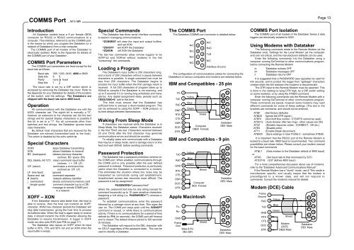
COMMS Port ... let’s talkPage 13IntroductionAll Datataker models have a 9 pin female (DE9)connector for RS232 or RS423 communications to acomputer. This interface, referred to as the COMMS port,is the means by which you program the Datataker (or anetwork of Datatakers) from a host computer.The COMMS port of all models of the Datataker iselectrically isolated. Refer to the Appendix for details ofthe COMMS port of your Datataker .COMMS Port ParametersThe COMMS port parameters are fixed except for thebaud rate as followsBaud rate 300, 1200, 2400, 4800 or 9600Data bits 8Parity none fixedStop bits 1The baud rate is set by a DIP switch which isaccessed by removing the Datataker top cover. Refer tothe Appendix for your Datataker for details of the locationof the switch, and the settings. The Datatakers areshipped with the baud rate set to 4800 baud.OperationAll communications with the Datataker are with theASCII character set. The eighth bit is normally a "0",however an extension to the character set (for the textstrings and for special display characters) is possible ifthis bit is set to a "1". For all commands other thanswitches and text strings, the Datataker ignores lowercase characters.By default most characters that are received by theDatataker are echoed (transmitted back to the host).This action is disabled by the echo switch /e.Special CharactersXOFF stops Datataker transmittingXON allows Datataker to transmitBS (backspace) deletes previous character(echoes BS space BS)DEL (delete, Alt 127) clears command input buffer(echoes < < CR LF)CR (return) terminates a command line(echoed as CR LF)LF (line feed) ignoredSpace and tab command separator# (hatch) network address identifier; (semicolon) directs command to memory card' (single quote) comment character (up to a CR)@ message to remote COMS portin a networkXOFF – XONIf the Datataker returns data faster than the host isable to receive, then the host can transmit an XOFFcharacter. Within two character periods the Datataker willstop data transmission, giving the host time to processits buffered data. When the host is again ready to receivedata, it should transmit the XON character allowing theDatataker to resume transmission. A logger in XOFFmode can also auto-XON (see P26 on page 11).The Datataker also issues an XOFF when its inputbuffer is 50%, 75% and 90% full and an XON when theinput buffer is empty.Special CommandsThe Datataker has three serial interface commandsto assist in managing communications.^ZCMSRST will clear the input and output buffers,and set XON.^ZSXOFF will XOFF the Datataker^ZQXON will XON the DatatakerThe last two commands allow remote loggers to beXOFF'ed and XON'ed without modems in the link"consuming" the commands.Loading a ProgramThe Datataker's input buffer is 250 characters long,and a burst of 250 characters without a pause betweencharacters is possible. A single command line must beless than 250 characters. The Datataker begins toprocess the input buffer when the first carriage return isreceived. A full 250 characters of program takes up to500mS to compile if the Datataker is not scanning, andup to 5 seconds if it is running long schedules and manyalarms. Any digital assignment delay periods such as1DSO(1000)=0 add to this time.The host must ensure that the Datataker hassufficient time to process a down-loaded program. Thiscan be achieved by using the XOFF – XON protocol, orby time delays between transmissions.Waking From Sleep ModeIf characters are received while the Datataker is inSleep Mode, the Datataker wakes. Characters receivedin the first 75mS are lost. Characters received between25 and 75mS after the first character may generatecommunications errors and should be avoided.To reliably wake and communicate with a Datatakerthat may be in sleep mode, send a carriage return or linefeed and wait 300mS before sending commands.Password ProtectionThe Datataker has a password protection scheme onthe COMS port. When enabled, communications throughthe COMS port is only possible after the user definedpassword is entered. Password protection is particularlyuseful when the Datataker is connected to a modem.This eliminates the situation where line noise may beinterpreted as commands during call establishment.Unauthorised access also becomes more difficult. Thepassword is set by assignment:PASSWORD="password text"where the password text may be any string (except forcommand keywords) up to 10 case sensitive characters.Assigning a null string (i.e. PASSWORD="") removes apassword.To establish communications, enter the passwordfollowed by a carriage return at any time. This signs theuser on. The COMS port stays open until the SIGNOFFcommand is issued, or while there is communicationsactivity. If there is no communications for a period of timedefined by P14 (in seconds), the COMS port will timeoutand is closed. The default timeout period is 300 seconds(5 minutes).The Datataker will respond to the DEL character with
Networking ... distributed processingPage 14IntroductionDatataker models with an RS485 network port can beconnected in a local area network (LAN) with up to to 32Datatakers. A total of 1000 meters of cable is allowed in thenetwork.The proprietary network protocol has error detection andcorrection, and operates at 1200 baud over a single twistedpair of polarised wires. Datatakers are wired in parallel sothat all "NET+" screw terminals are connected to one wireand all "NET–" screw terminals are connected to the secondwire. Ideally, the network cable should have a shield that isgrounded at a single point.+ –NetCOMNetwork - a Twisted Pair of Wires (note polarity)+ –NetCOM"Local Logger"RS232 orRS423interface+ –NetCOMDatatakersThe host computer may be connected to any of theDatatakers (referred to as the local logger) in the networkthrough its COMS port. Data is returned to the COMS port ofthe local logger. P21 will allow this return address to be overridden - see "Parameters" on page 11.You can connect host computers to different Datatakersin a network. If each host is simply polling for data withimmediate schedules (see page 3), operation is predictable.If you enter repeating schedule types (RA, RB, RC or RD),then the data generated by these schedules will only beavailable to the host that issued them.Addressing DatatakersThe host may issue commands to any Datataker byplacing an address prefix at the beginning of a commandline:#n commands send commands to logger n## commands send commands to all loggerse.g.#5 RA1M 3Vwill command logger 5 to return to the host the voltage onchannel 3 every minute.Take care in using the global address ## when thecommand returns data, as the data from the loggers may bemixed and not easily separated. The global address isparticularly useful for setting the time, switches andparameters on all loggers:## T=11:23:30## /N/c/u/L P22=44+ –NetCOM+ –NetCOMHost ComputerThe address is optional for commands to the locallogger. Remote loggers must be addressed.Identifying the Data Source /LData returns by to the COMS port that made the request,unless changed by P21. To identify the data source, it isrecommended that all loggers in the network are issued withthe /L switch so that all Datataker responses have the loggeraddress at the beginning of each schedule's returned data.For example, for channels 1..3TT with switches set to/n/c/u/L and P22=32 (i.e. "space" - the default), the returneddata will have the following format:19 25.6 45.8 32.7If the /N switch is enabled (default), then the word"Datataker" is added to the logger address and the channelsare identified:Datataker 19 1TT 25.6 2TT 45.8 3TT 32.7If the units text switch is also on /U then the returned datawill look like the following:Datataker 191TT 25.6 Deg C2TT 45.8 Deg C3TT 32.7 Deg CNote that the logger address is placed at the beginning ofeach schedule's scan report. Data unloaded from the datamemory is treated identically.An alternative method to identify the Datataker from whichthe data is being sent is to load the Datataker with anidentifying string (e.g. $="Logger 19"), which is then includedin a schedule. For example the program:#19 $="Logger 19"#19 $ 1..3TT P22=44 /n/uwill return data to the host:Logger 19,25.6,45.8,32.7This method allows any string of up to 80 characters to beused as the logger identification. Special control charactersmay be included to assist in identification. See "Text String"on page 6 and "ASCII-Decimal Equivalents" on page 23.Setting the AddressThe Datataker address is set by a DIP switch in a binarycode. The DIP switch is accessed by removing the Datatakertop cover. Refer to the Appendix for your model Datataker forlocation and setting details. Datatakers are shipped with theaddress set to 0.If you give two loggers the same address, then networkerrors will occur when commands are directed to them.The Datataker models without network support alsohave an address, however it only serves for Datatakeridentification.Network and ModemsThe network can be extended by modems or radiomodems that can operate at 1200 baud and can automatically"turn-around" (change direction of data transfer). This is animportant issue with radio modems, where changing fromtransmit mode to receive mode can take as long as 500mS.The network turn-around time can be adjusted byparameter P7 in increments of 14mS. For example settingP7=22 would set the turn-around time to 300mS.There is no electrical signal to indicate turn-around. Themodem must detect when the Datataker is sending networkdata and rapidly switch to transmit mode. The Datatakerdoes not issue any message preamble. See the "DatatakerAdvanced Communications <strong>Manual</strong>" for details.Network modems must be "dumb". As the Datatakeralready provides an error correcting protocol, the modemmust not overlay an additional protocol layer. This appliesparticularly to radio modems where it is common to find errorcorrection built-in.Messages to COMS PortsYou can connect other devices to the remaining DatatakerCOMS ports. These may be a printer, a terminal or anothercomputer.The following commands allow text to be sent to theseports from the network host:e.g.+ –NetCOMSNetwork - a Twisted Pair of Wires (note polarity)+ –NetCOMSHost Computer+ –NetCOMSDatatakersPrinter@n text sends tex to COMS port of logger n@@ text sends text to all COMS ports@27 Hello there^M^J+ –NetCOMSwill direct the message to the COMS port of logger 27. Thetext string may be up to 250 characters long, and can includecontrol characters in the text as illustrated above (e.g. seealso "ASCII Characters" on page 23).Networking and Power DownNormally when a logger is asleep, it will not wake whennetwork activity begins. To ensure proper operation theloggers must be kept awake by setting P15=2. Alternativelyloggers can be programmed to be awake (by ALARMs) whennetwork communications are expected.Programming a NetworkThe main difference between operating a single loggerand a network of loggers is that the task of managing thereturned data and alarms becomes more complex. The bestmethod for managing the network will depend on the goals:• data logging• monitoring for alarm conditions• rapid real-time response• simplicity of programming• telemetry or modem connection+ –NetCOMSSecond HostDon't underestimate the complexity of managing a largevolume of data. Unloading a Datataker with a large memorycard over a network link can take over an hour.There are two distinct class of networks: part-time andreal-time networks.Part-Time NetworkIf the main task is data logging, then communicationsbetween the network and the host computer can beinfrequent (hours, days or weeks) and so you can programand unload each logger in the network individually. This is thesame as using a single logger, except that you must addresseach logger.Real-Time NetworkWhere the emphasis is on rapid response or trackingconditions, network speed becomes vital. There are manyways the network can be managed, however as a generalrule more speed leads to more complexity in host software.1. Poll channels one at a time. This method is simple butslow. Any polling over a network can take up to two secondsbefore a reply is received. As only one operation isundertaken at a time, there can be no confusion about thesource of the data. For example:poll (assume /n/u) #21 2Vreceive 156.54poll#29 5TTreceive 105.1The polling speed can be as low as one channel every twoseconds.2. Poll by alarms one at a time using the ?n command(see "Polling Alarm Data" on page 9). This is similar tomethod 1, but is slightly faster as it returns the last reading ofthe alarm channel rather than initiating a new scan.3. Poll channel groups using the RX schedule (see"Polled Schedule" on page 3). For example:program logger 21 #21 RX 2V 3..4TT(FF1) /u/nlogger 29 #29 RX 1..4DS /u/npoll logger 21 #21 Xreceive 156.54 23.5 28.9poll logger 29 #29 Xreceive 0 1 1 0This method retains most of the simplicity of method 1, but isfaster - up to 20 channels every two seconds.4. Poll all alarms on a logger by the ?ALL command(see "Polling Alarm Data" on page 9). This is similar to theprevious method but is faster at 30 channels every twoseconds.5. By frequent Unloads (see "Data Logging and Retrieval"on page 8). This method uses the Datataker's store as anexpanded output buffer, that is cleared after each unload bythe CLAST command. For exampleprogram all loggers ## /u/n P25=36program logger 21 #21 RA10S 2V 3..4TT LOGONlogger 29 #29 RA10S 3TT 1..4DS LOGONunload logger 21 #21 Ureceive 156.54 23.5 28.9receive 157.33 23.3 29.7$clear data #21 CLASTunload logger 29 #29 Ureceive 105.6 0 1 1 0receive 104.4 0 0 1 0$clear data #29 CLASTThe unload steps are repeated for the duration of themonitoring task. This method ensures regular sampling bynormal schedules.6. By synchronous returns from all loggers that have beenprogrammed by standard schedules (RA, RB, RC and RD -see page 3). This is the most flexible method, as it allowseach logger full control of the schedule scanning. However inorder to work, it requires that the host software use morecomplicated data routing and time stamping techniques.7. The use of the fixed format mode /H is recommendedfor real-time networks. (See "Fixed Format Mode" and the"Datataker Advanced Communications <strong>Manual</strong>").