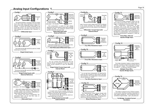
Analog Input Configurations 1Config 1VShieldThe optional Shield is necessary when the signalsource has a high output impedance or when noisepick-up from other (especially power) cables is aproblem. A Guard (not shown) connected to theexcite (✱) terminal can help reduce the effects ofcable leakage and capacitance (see "Glossary" onpage 23).Differential InputConfig 2V1 V2 V3Config 4VR1R1R2attenuation = (R1+R2)/R2✱RSingle Ended InputsExamples1V5FExamples1V(10)3TJ(2)5+V(100)Attenuated voltage inputs let you measure largevoltages, extend the common mode range andprovides greater input protection. Differential orsingle ended measurement is possible.For sensors with built-in amplification theattenuation factor can be less than unity, ornegative for a sign reversal.Attenuated InputR2✱RExamples1+V3✱AS1-..3+TKThe excite terminal (✱ )cannot be used as a singleended input on the DT50.Config 3V V V1 2 3The excite terminal (✱) cannot be used as a singleended input on the DT50.Single Ended Inputs withExternal Reference✱R✱RSEExamples1-V(X)2+..5-F(X)5+LM35(X)SE RefConfig 5VConfig 7PowerSupply +–IExamples1#I1#..10#I5#LYou can combine this arrangement with theExternal Shunts arrangement to give four singleended current channels for each full differentialchannelSingle Ended Current Input withInternal ShuntConfig 8+PowerSupply-ShuntI 1"bus bar"R1R1this line commonR2to other channelsattenuation = (R1+R2)/R2ShuntR2This configuration is useful for high voltagedifferential input and situations where high accidentalvoltages are likely. For maximum common moderejection match the attenuator pads.Attenuated Input withExternal ReferenceI 2Shunt✱RGGroundExamples1*..1-I(X)5+L(X)6-AD590(X)To avoid cross channel coupling, connect thebottom of the shunts with the minimum of sharedresistance to the SE ref. take-off point.The excite terminal (✱ ) cannot be used as asingle ended input on the DT50.Single Ended Current withExternal ShuntI 3✱RSE✱RGSEExamples1+V(11,X)3+TJ(X,2)5-V(X,100)SE RefGroundConfig 6R1✱ Examples1V(10)VR25V(100)close to GNDRatten. = (R1+R2)/R2Attenuated voltage inputs for situations where onesignal line is always close to ground potential.Half Attenuated Differential InputGGroundSE RefRConfig 8aPowerSupply +Config 9RConfig 10RFour Wire Resistance Inputlink✱R✱RThree Wire Resistance InputConfig 11linklink *Two Wire Resistance InputExamples2R(4W)3R(4W,I)5PT392(4W)Examples1R2R(I)3PT385Examples3R1..5R4PT385* You can get lead compensation by replacing thelower link with a resistor of value equal to the totallead resistance. This configuration is recommendedonly for resistances > 500ΩConfig 12R1R2–nR(4W)n-RIshunt(10 to 100Ω)Note: Common mode voltage limits must be adheredto for correct operation. For models with CMOSmultiplexers this is ±4 volts relative to the Datataker'sground.Differential Current Input withExternal ShuntThe measurement current passes through bothresistors. By definition nR(4W) and n-R willmeasure R1 and R2 respectively. This configurationdoes not provide lead compensation for R2.Mixed Resistance Input✱R✱R✱RExamples2I1..10I5L(10)Examples5R(4W)5-R(II)Config 13activearmRc can be a bridge completion resistor (for thesame value as the active arm) located near thelogger, or preferably an active arm of the bridge.This configuration compensates for leadresistance, and in the case of a half bridge,temperature compensation. For quarter bridge 120Ωfoil strain gauge the resolution is 2µStrain. Theconfiguration is also useful to read the position ofthe wiper of a potentiometer. The channel factor isset to the potentiometer's resistance (≤ 5KΩ) eg2BGI(I,2000).Three Wire, Half andQuarter Bridge InputConfig 14To otherbridgesConfig 15Bridge2.500mA2.500mARcRclinkThe bridge is powered by the 2.500mA constantcurrent source, resulting in readings independent oflead length (resistance). This arrangement has asensitivity of approximately 1 ppm per active arm.✱RTo other channelR terminals✱RFull Bridge, Constant CurrentExcitationExamples1BGI(120.0)3BGI(I,350)Examples1..5BGI(350)4BGI2BGI(Y1)The bridge completion resistor is shared betweenchannels. Its value is equal to the nominal value ofthe "unknown" resistor. The configuration is similarto Config 11 - no reference channel is needed.Multiple Three Wire,Quarter Bridge Inputs✱R✱RExamples3BGI(4W)4BGI(120,4W)5V(II,Y3)Page 19
Analog Input Configurations 2 Digital Configurations Wiring IndexConfig 18AD590AD592Config 16BridgeConfig 17BridgesThis is a combination of Config 1 for the referencechannel and Config 3 for measurement channels.The half bridge completion resistors Rc are bestlocated near the active bridge arms, however they canbe located at the loggerHalf and Quarter Bridge,Ratiometric Input with Shared HalfBridge CompletionBottom view ofmetal can versionR cR c1µA/°KBridge SupplyThe (external) bridge supply should not exceed2.5V unless the reference channel input isattenuated.The difference between six and four wireconnection is the location of the reference channelmeasurement point - at the bridge or at the logger.Examples2#AD5902#I(V)Note: Sensor power can be any 4 to 12 volt source.The above arrangement is equivalent to Config 7.Differential and single ended wiring (Config's 1 & 2)with external shunts may be used.AD590 Temperature Input✱R✱RSix (& Four) Wire, RatiometricBridge InputG5VSE✱RG✱R✱RReferencechannele.g.3V(BR,N)Measurementchannel e.g.5BGV(N)2BGV(108)Ground5V switchedSE RefReferencechannele.g.1V(BR,2)GroundMeasurementchannelse.g.2*BGV(N,X,23)3+BGV(N,X)Config 19LM335adj+-Bottom view50KCal.10K10Koptional potentiometerlinkWith internal sensor power as illustrated, theupper response is limited to approx. 70°C. Externalpower should be current limited.Be aware of self heating effects - a 500µA sensorcurrent can cause 1.5°C error. A fourth wire to thesensor's negative pin in place of the link will improveaccuracy. Single ended input as in Config's 2 & 3.Config 21LM34 +outLM35 -Bottom view*Config 20LM34LM35+out-Bottom viewof TO92 case1N914's✱RLM335 Temperature Input10mV/°F or10mV/°C10K2K2*linkExamples2LM3352+LM3352V(2,V)This configuration limits the sensor's lower rangeto approx. 10°F and 10°C for the LM34 and LM35respectively due to the lack of a pull-down capacity.Accuracy is improved if the link is replaced by afourth wire to the sensor's negative pin. Without thelink the sensor is read as a single ended input as inConfig's 2 & 3. Sensor power may be externallyderived (eg 5V) to free the Excite terminal.LM34 & LM35 Temperature InputThis arrangement allows full range measurement.Multiple single ended sensor connection (Config 3)is possible by connecting the LM35 negative pins toSE ref. The diodes can be shared. Sensor powercan also be derived from external sources.This resistor may be needed to prevent sensoroscillation with long leads. See manufacturer's data(National Semiconductor Corp.) for more details.✱✱LM34 & LM35 Temperature InputRRExamples5LM355+LM35Examples2LM355V(V)Config 22The digital and counter inputs both employ10KΩ pull-up resistors to 5 volts, allowing the use ofvoltage free contacts. The thresholds are 3.5V for a "1". During sleep mode thedigital inputs are inoperative, however the highspeed counters remain active.Example above also shows wiring for the onephase encoder up-down counter.Config 23PowerSupply+-1234GDigitalOutput /InputGroundThe bidirectional digital channels can sink 200mAfrom up to a 30 volt supply. The solid state switch isnot protected against sustained over currents.For inductive loads parallel reverse diodes arerecommended although not essential as theDatataker has internal transient protection.Relay Connection - Externally PoweredConfig 24330ΩLEDConfig 251KΩ✱RExamples5+AS(II)5–AS3AS(1500)ExternallypoweredInternallypoweredThe power source must be able to providesufficient voltage to exceed the Analog States'sthreshold which defaults to 2500mV. Ensure inputvoltages do not exceed Datataker's common moderange.Digital Input via Analog Inputs5V12345V switchedDigitalI/OThe internal 5V switched (off in sleep mode) supplyis limited to approximately 100mA. The saturationON voltage drop of the switches is 1 volt so the relaysmust be able to activate at 4 volts over the expectedtemperature range.Relay and LED ConnectionInternally Powered3D4DGDigitalinputsGroundDigital and Counter InputExamples1..4DS3C(R)1PEExample3DSO=1AD590, AD592 18Attenuated Differential Voltage Input 4, 6Attenuated Single Ended Voltage Input 5Page 20Bridge - 3 wire, Half and Quarter 13, 14Bridge - 4 wire, Full, Constant Current 15Bridge - 6 wire, Full, Voltage Excitation 16, 17Copper RTD 9, 10, 11, 12Counter Input - Low Speed 22Counter Input - High Speed 22Current Input with External Shunt 8, 8aCurrent Input with Internal Shunt 7Current Loop 4 - 20mA , External Shunt 8, 8aCurrent Loop 4 - 20mA , Internal Shunt 7Differential Voltage Input 1, 4Digital Input 22Digital Input on an Analog Input 25Digital Output 23, 24Frequency Input 1, 2, 3, 4, 5, 6, 25Guard Screening 1LED on Digital Output 24LM34, LM35 20LM335 19Nickel RTD 9, 10, 11, 12Phase (with AC Option) 2, 4Phase Encoder 22Platinum RTD 9, 10, 11Potentiometer 13Relay on Digital Output 24Resistance Input - 2 wire 11,12Resistance Input - 3 wire 10Resistance Input - 4 wire 9Single Ended Voltage Input 2, 4Single Ended Voltage, External Ref. 3, 5Thermistor 9, 10, 11,12Thermocouple 1, 2, 3Vibrating Wire Sensors 1, 2Voltage Input 1, 2, 3, 4, 5, 6Note: the number references relate to thewiring configuration.