UM-0046-A0 - DT500 Concise Users Manual - dataTaker
UM-0046-A0 - DT500 Concise Users Manual - dataTaker
UM-0046-A0 - DT500 Concise Users Manual - dataTaker

Create successful ePaper yourself
Turn your PDF publications into a flip-book with our unique Google optimized e-Paper software.
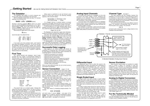
Getting Started ... also see the Getting Started with Datataker User’s GuidePage 1The Datataker ....The Datataker data logger is a tool to measure andrecord a wide variety of parameters in the real world.With the Datataker simple tasks are easy. For exampleentering in the command line:RA5S 1..5TJ LOGON [return]declares a reporting schedule (RA5S) which is to reportevery five seconds (RA5S) the temperatures on five Type Jthermocouples (1..5TJ), and to log or store the results inmemory (LOGON). Programs are executed only after thereceipt of a (carriage) return character.Recovering the logged data is even simpler:U [return]returns the data in the default format:1TJ 384.7 Deg C2TJ 335.2 Deg C3TJ 367.1 Deg Cetc.If you want to do more complex tasks, you'll need tolearn about the Datataker commands. You can be sure thatthe Datataker has the flexibility to handle very complexsituations, once you become familiar with the full commandset. The more familiar you are with the Datataker's features,the better you'll be able to use it. Explore in detail thefeatures that are of most interest.First TimeThe Getting Started with Datataker User’s Guideincluded with your logger is recommended reading forfirst-time users. The manual will quickly teach you how toprogram the Datataker. Alternatively you may read on!The first task in preparing the Datataker is to establish acommunications link with your computer. Connect thecommunications cable supplied between the Datataker andto any IBM or compatible computer. Load and run eitherDeTerminal for DOS or DeTerminal for Windows, which willconfigure your computer's RS232 port (COM1 by default) tomatch the Datataker's communications parameters. Theseprograms also provide a terminal type interface forprogramming the Datataker and for receiving data.If you are using a different computer type, construct orpurchase a communications cable – see "COMS Port" onpage 13 for wiring details. Load and run a terminalemulation or communications program, and ensure that thecomputer's communications parameters are set to theDatataker's default settings:Baud rate 4800Data bits 8Stop bits 1Parity noneProtocol XON - XOFFThe second task is to connect power. Connect theoutput from the power adaptor (240 or 110 Vac to 12Vdc) tothe two screw terminals marked "~ ~" or "AC/DC" dependingon the Datataker model. Polarity is not important.A word of caution – do not connect external power to theterminals labelled "Bat". These are reserved for an externalbattery, and have a limit of 9 volts DC. See "Power andBattery Connection" on page 15 for information on powerconnection and power consumption.When power is switched on, the red Convert Lampflashes for about half a second. The following messageappears on the computer display:Datataker 0 Version 5.xxInitializing ... DoneIf a charged internal or external battery is alreadyconnected to the logger, then this will not occur as the unit isalready powered and does not perform another "cold start".If communications are OK, then typing an upper case Tfollowed by the Enter key (or Alt L in DeTerminal) returnsthe current time (this may be different to your local time):Time 09:10:55The Datataker only responds to upper case characters,except for the Switch command (see Switches on page 11).Use lower case characters to document and add clarityto commands. For example Time is the same as T andReport_schedule_A_every_15_Minutes is the same asRA15M, (using the underscore character to improve thereadability as a "space" character is a command separator).If communication is not successful, check the COMScable and COMS port parameters. Change the Datataker'sDIP switches (see the Appendix for your Datataker) or thecomputer's parameters so that both are the same.Successful Data LoggingData logging is an orderly process and should beundertaken in a systematic way. Clearly define the purposefor data logging so that the data you collect maximises theknowledge gained. Consider the following:• identify the parameters to be measured• select sensors and number of channels• determine sensor output scaling• determine how data is to be processed and reported• decide on sample frequency - minimise redundancy• calculate volume of data to be collected• decide method of data recovery and archiving• consider power consumptionWhen you have defined the task, you can connect sensorsand program the Datataker.Sensor Connection ... pages 4, 19, 20You must know the output signal for each sensor. Makesure that the input to the Datataker does not exceed ratings.As a general rule, the voltage on any analog input terminalshould be within –3.5 to +3.5 volts relative to Datatakerground. Datataker models with a relay multiplexer andattenuator can accept higher input levels.Select the most appropriate channel type for eachsensor from the table on page 4. The second last columnshows appropriate wiring configurations from pages 19and 20. Connect the sensors accordingly.Use channel options to modify channel function. In achannel definition these are listed in brackets immediatelyafter the channel type. The table on page 5 describes thechannel options.Test each sensor by declaring a simple schedule. ForexampleRA1S 2PT385(4W)will return every 1 second (RA1S – see page 3) thetemperature of a platinum resistance temperature sensor(PT385 – see page 4) connected as a four wire resistance(4W channel option – see page 5) on channel 2.Analog Input ChannelsAn analog input channel on a Datataker is a four wireconnection that allows voltage, current, resistance andfrequency to be measured. These are the fundamentalsignals output by most sensors. It is not necessary to use allfour connections - two are often adequate.As can be seen in the simplified drawing of a Datatakerchannel below, there is a multiplexer and a programmableinstrumentation amplifier between the screw terminals andthe analog to digital converter.The multiplexer is essentially a patch board that directssignals from the channel screw terminals to the amplifierinputs. Many different connections are possible.Four input screwterminals for one ofmany analog inputchannelsexcite ✶+ input +– input –return RGround(shared)Datataker Channel100.0Ω0.1%Differential InputA differential input is one in which the signal is thevoltage between two wires, and neither wire is necessarily atground potential. On the Datataker the + and – terminalsprovide for differential input. The multiplexer patches thechannel's + terminal to the amplifier's + input and the– terminal to the amplifier's – input. This patching isachieved by defining the channel number and type (seepage 4). For example a differential voltage on channel oneis patched by the channel definition 1V.Single Ended InputA single ended input also provides a signal voltagebetween two wires, except that one of the wires must be atground potential. On the Datataker this "grounded" wire isconnected to the channel's R terminal (R for return). Theother signal wire is connected to any one of the other threeterminals.To patch a single ended channel the channel number isgiven a suffix indicating the terminal to which the secondwire is connected. For example a single ended voltage inputapplied to channel one between the R and + terminalswould be patched by the channel definition 1+V.You can apply three single ended inputs to eachDatataker channel. These use the suffix's +, – and ✶(asterisk). Thus the three single ended voltage inputs onchannel one would be 1+V, 1–V and 1✶V. Note that the✶ single ended input in not supported on the DT50.Channel Type .. see page 4The input channels are very versatile, however theDatataker is not smart enough to know what type of sensoris connected. It must be told. A channel is defined by achannel type that determines how the multiplexer is patchedand how the readings are to be processed. There are morethan thirty different channel types.The same channel may be read using different channeltypes. For example a thermocouple may be read as athermocouple or as a voltage. The command1TK 1Vwill return both a temperature and a voltage based on tworeadings of the same sensor.Sensor excitation:250µA, 2.50mA or 4V+–To 15 bit analog todigital converterInstrumentation amplifier(gain x1, x10 or x100)Analog multiplexer and signal routershowing connection for a differentialinput with sensor excitation (solid lines),and a single ended input (broken lines)A Standard Datataker Analog Input ChannelSensor ExcitationMany sensors require power (or excitation) to enablethem to output a signal. For example to read thetemperature of a thermistor (a temperature dependentresistor), excitation current is passed through the thermistorto generate a voltage drop that can be measured.The Datataker has three different excitation sources –250µA, 2.50mA and 4V. These are output on the excite ( ✶)terminal of each channel, when the channel is read. Thisaction is automatic for most sensor types, but may also beevoked as a channels option.Analog to Digital ConversionThe Datataker converts its input signals to a frequency,and then measures the frequency over one line cycle period(20.00mS or 16.67mS). This method provides high noiserejection and good signal averaging over the sample period.Many sampling parameters can be adjusted by means ofchannel options (page 5), switches and parameters (page11). These include calibration, settling time, sampling timeand extended or multiple sampling. The default values ofthese parameters are suited to the majority of sensors. See"ADC Details" page on 18.For the Technically MindedTo gain an understanding of how your Datataker works,study the "Simplified Circuit" on page 22. This will help youto exploit many of Datataker's features.