UM-0046-A0 - DT500 Concise Users Manual - dataTaker
UM-0046-A0 - DT500 Concise Users Manual - dataTaker
UM-0046-A0 - DT500 Concise Users Manual - dataTaker

You also want an ePaper? Increase the reach of your titles
YUMPU automatically turns print PDFs into web optimized ePapers that Google loves.
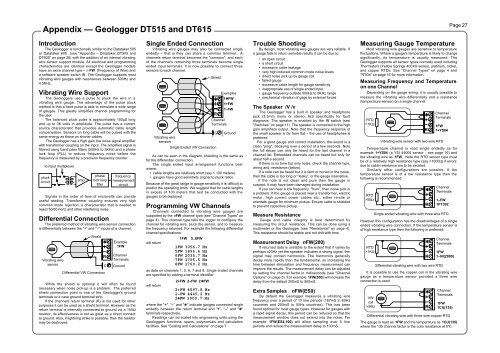
Appendix — Geologger DT515 and DT615Page 27IntroductionThe Geologger is functionally similar to the Datataker 505or Datataker 605 (see "Appendix – Datataker DT505 andDT605" on page 26) with the addition of an internal vibratingwire sensor support module. All electrical and programmingcharacteristics are identical except the Geologger modelshave an extra channel type – n FW (Frequency of Wire) anda software speaker switch /V. The Geologger supports mostvibrating wire gauges with resonances between 600Hz and4.5KHz.Vibrating Wire SupportThe Geologgers use a pulse to pluck the wire in avibrating wire gauge. The advantage of the pulse pluckmethod is that a fixed pulse is able to stimulate a wide rangeof gauges. This greatly simplifies channel programming forthe user.The balanced pluck pulse is approximately 150µS longand up to 36 volts in amplitude. The pulse has a currentsource characteristic that provides automatic cable lengthcompensation. Sensors on long cable will be pulsed with thesame energy as those on shorter cables.The Geologger has a high gain low noise signal amplifierwith transformer coupling on the input. The amplified signal isfiltered using band pass filters (500Hz to 5KHz) and a phaselock loop (PLL) to reduce frequency noise before thefrequency is measured by a precision frequency counter.to input multiplexerpluckcircuitSignals in the order of tens of microvolts can provideuseful reading. Transformer coupling ensures very highcommon mode rejection, a characteristic that is needed toreject 50/60 hertz and other interfering noise.Differential ConnectionThe preferred method of vibrating wire sensor connectionis differentially between the "+" and "–" inputs of a channel.Vibrating wiresensorampphaselock loopfilterShieldWhile the shield is optional it will often be foundnecessary when noise pick-up is a problem. The preferredshield connection point is one of the Geologger's groundterminals or a case ground terminal strip.If the channels return terminal (R) is not used for otherpurposes it can be used as a shield terminal. However as thereturn terminal is internally connected to ground via a 100Ωresistor, its effectiveness is not as great as a direct connectto ground. Also, if lightning strike is possible, then the resistormay be destroyed.✱RDifferential VW ConnectionGfrequencymeasurementcircuitExample1FWChannelTerminalsGroundSingle Ended ConnectionVibrating wire gauges may also be connected singleendedly – that is they can share a common terminal. Achannels return terminal becomes the "common", and eachof the channel's remaining three terminals become singleended input terminals. It is now possible to connect threesensors to each channel.As can be seen in the diagram, shielding is the same asfor the differential connection.The single ended input arrangement functions bestwhere:• cable lengths are relatively short (say < 100 meters)• gauges have good sensitivity (signal to pluck ratio)Because of the great range in gauge sensitivity it is difficult topredict the operating limits. We suggest that for cable lengthsin excess of 100 meters that test be conducted with thegauges to be deployed.Programming VW ChannelsChannels connected to vibrating wire gauges aresupported by the nFW channel type (see "Channel Types" onpage 4). This channel type tells the logger to configure thechannel for vibrating wire, pluck the sensor, and to measurethe frequency returned. For example the following differentialchannel specifications:will return1FW 5..8FW1FW 3056.7 Hz5FW 1896.4 Hz6FW 2035.7 Hz7FW 1705.5 Hz8FW 1769.2 Hzas data on channels 1, 5, 6, 7 and 8. Single ended channelsare specified by adding a terminal identifier:will returnVibrating wiresensors2+FW 2–FW 2✱FW2+FW 4597.8 Hz2–FW 4445.2 Hz2✱FW 3909.7 HzShieldSingle Ended VW ConnectionChannelTerminalsGroundwhere the "+", "–" and "✱" indicate gauges connected singleendedly between the return terminal and "+", "–" and "✱"terminals respectively.Readings can be scaled into engineering units using theGeologgers functions, spans, polynomials and calculationfacilities. See "Scaling and Calculations" on page 7.✱RGExamples1✱FW1+FW1–FWTrouble ShootingBy design, most vibrating wire gauges are very reliable. Ifa gauge fails to return sensible results it can be due to:• an open circuit• a short circuit• excessive cable leakage• very high induced common mode noise levels• direct noise pick up by gauge coil• failed gauge• excessive cable length for gauge sensitivity• inappropriate use of single ended input.• gauge frequency outside 500Hz to 5KHz range• mechanical vibration of gage by external forcesThe Speaker /V /vThe Geologger has a built in speaker and headphonejack (3.5mm mono or stereo, 8Ω) specifically for faultdiagnosis. The speaker is enabled by the /V switch (see"Switches" on page 11). The speaker is connected to the highgain amplifiers output. Note that the frequency response ofthe small speaker is far from flat – the use of headphones ispreferred.For a good gauge and correct installation, the sound is aclean "ping", decaying over a period of a few seconds. Notethe full decay can only be heard for the last channel in achannel list. Embedded channels can be heard but only forabout half a second.If there is no tone but only noise, check the channel type,wiring and resistance (below).If a note can be heard but it is faint or buried in the noise,then the cable is too long or "leaky", or the gauge insensitive.If the note is not clean and pure then the gauge issuspect. It may have been damaged during installation.If you can hear a low frequency "hum", then noise pick isa problem. If the gauge is placed near a transformer, electricmotor, high current power cables etc., either re-site ororientate gauge for minimum pickup. Ensure cable is shieldedto prevent capacitive pickup.Measure ResistanceGauge and cable integrity is best determined bymeasuring the circuit resistance. This can be done using amultimeter or the Geologger (see "Resistance" on page 4).This resistance should be stable and not drift with time.Measurement Delay nFW(200)If returned data is unstable to the extent that it varies byperhaps ±20Hz yet the speaker indicates a strong signal, thesignal may contain harmonics. The harmonics generallydecay more rapidly than the fundamental, so increasing thetime between stimulation and frequency measurement canimprove the results. The measurement delay can be adjustedby setting the channel factor in milliseconds (see "ChannelOptions" on page 5). For example 1FW(500) will increase thedelay from the default 200mS to 500mS.Extra SamplesnFW(ES9)By default the Geologger measures a vibrating wirefrequency over a period of 10 line periods (167mS in 60Hzcountries and 200mS in 50Hz countries). This has beenfound optimal for most gauge types. However for gauges witha rapid signal decay, this period can be reduced so that themeasurement window does not extend into the noise. Forexample 1FW(ES4,100) will allow sampling over 5 lineperiods and reduce the measurement delay to 100mS.Measuring Gauge TemperatureMost vibrating wire gauges are sensitive to temperaturefluctuations. Where a gauge's temperature is likely to changesignificantly, its temperature is usually measured. TheGeologger supports all sensor types normally used includingThermistors (Yellow Springs 400XX series), platinum, nickel,and copper RTDs. See "Channel Types" on page 4 and"RTDs" on page 16 for more information.Measuring Frequency and Temperatureon one ChannelDepending on the gauge wiring, it is usually possible tomeasure the vibrating wire differentially and a resistance(temperature sensor) on a single channel.RTD>1KΩTemperature channel is read single endedly as forexample 1+YS04 (a YSI 44004 sensor - see page 16) andthe vibrating wire as 1FW. Note the RTD sensor type mustbe of a relatively high resistance type (say >1000Ω) if errorsdue to cable resistance are to be avoided.Similarly other configurations are possible. If thetemperature sensor is of a low resistance type then thefollowing is recommended:RTD>50ΩChannelTerminals1–FW1PT392Single ended vibrating wire with three wire RTDHowever this configuration has the disadvantages of a singleended vibrating wire connection. If the temperature sensor isof high resistance type then the following is preferred:RTD>1KΩIt is possible to use the copper coil in the vibrating wiregauge as a temperature sensor provided a three wireconnection is used:VWcoil>50ΩVibrating wire sensor with two wire RTDThe gauge is read as 1FW and the temperature as 1CU(135)where the 135 channel factor is the coils resistance at 0°C.✱✱Differential vibrating wire with two wire RTDRR✱RChannelTerminals1FW1+YS04ChannelTerminals1FW1–NI(2000)ChannelTerminals1FW1CU(135)Differential vibrating wire with three wire copper RTD✱R