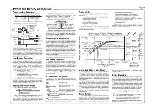
Power and Battery Connection ... take carePowering the DatatakerThe Datataker data loggers can be powered from:Source Typical Range Connection TerminalsAC 9 – 18Vac ~AC/DC and ~AC/DCDC 11 – 28Vdc ~AC/DC and GNDBattery 6 – 9 Vdc + Bat and –BatRefer to the Appendix for details of your Datataker. Thefollowing diagram shows a simplified power circuit:AC/DCPower~~External BatteryConnectionsBat +Bat –GndProtectionCircuit6.9V Switch ModeRegulator(–9.2mV/°C)1000µF0.22ΩCaution: If a DC supply is grounded, it MUST be a negativeground. An AC supply MUST NOT be grounded.If an external battery is connected to a Datataker 500,600, 505, 605, 515 or 615 data logger which has an internal6V gel cell battery, then the external battery must also be a6V gel cell battery, and MUST be connected with the correctpolarity, or damage WILL occur.Low Power OperationThe Datataker uses little power, and a set of six alkalineD cells can power the logger for over one year. Howeverprecautions must be taken to avoid excessive current draw.The Datataker has two states - wake and sleep. While inthe wake state the logger is fully active and draws up to500mA, but typically 120mA. In the sleep state only thecounters (nHSC), clock and the wake circuit remain active,and current draw is reduced to less than 0.4mA.The Datataker will wake when:• any scheduled scan becomes due• a memory card is inserted• characters are received at the COMMS port• the wake terminal is grounded• a key is pressed on display versionsThe Datataker will sleep unless the program inhibitssleeping by setting P15=2, or by rapid scanning. Make surethat input channels (for alarms or data logging) are not beingsampled more frequently than is necessary.Setting the Power ModeP15 is used to set the power mode, as follows:P15 Sleep entry condition6.9V0 Sleep only if battery powered (default)1 Sleep if not busy2 Disable Sleep modeLead +Bat. –Alkaline +Gnd.When logger is awake, and P15=0, the battery current ismeasured every second. If less than 20mA is drawn from thebattery (because the battery is being charged from anexternal supply), then sleep mode is not entered. P15=1allows sleep mode without testing battery current.P17 sets the delay period in seconds that the Datatakerremains awake after a COMS, network, keypad or waketerminal activity ceases. The default is 30 seconds.P20 prevents nominated schedules from waking asleeping logger. This is done using a disabling bit mask:Immediate (128)RD - schedule (64)RC - schedule (32)RB - schedule (16)P20 bit mapmsb 7 6 5 4 3 2 1 0 lsbRZ - alarms (1)X - polled (2)RS - statistical (4)RA - schedule (8)The default is P20=0, which means that all schedulescan wake the logger when they become due. If for example,P20=65 (i.e. 64 + 1), then the RD and alarm RZ scheduleswill not wake the Datataker. P20 does not disable schedulesif the Datataker is already awake.Powering the MultiplexerPower consumption can be minimised by powering downthe input multiplexers of some models of Datataker while thelogger is in the sleep state. The factory preset for thesemodels is to power down the multiplexers in the sleep state.The current saving is approximately 150µA. Refer to theAppendix for your Datataker for precise details.The disadvantage of powering down the multiplexer isthat it may cause problems with some sensors. For inputsover about 0.5 volts, the input impedance drops from tens ofmegohms to hundreds of ohms. This may cause draw ofcurrent from sensors, and possibly inject some of thiscurrent into other sensors.Datatakers with relay multiplexers do not require theseconsiderations, since the relays are open circuit when off.The Wake TerminalA low state (less than 0.7 volts) on the Wake Terminalwill wake the logger within 300mS. The signal can begenerated by a relay closure, or an open collector NPNtransistor to ground. The Wake signal line has an internal1800Ω pull-up resistor to +5 Volts and requires a signal levelof less than 0.7 Volts.A permanent low state on the wake terminal will notprevent short periods (~100mS) of sleep if there is noscheduled activity! Only P15=2 keeps the Datatakerpermanently awake.A Low Power Program!You may find this framework useful when designing lowpower programs. After RESETing the Datataker, enter thefollowing program:P15=1 'sleep if not busyP17=5 'go to sleep quickly/u/n 'disable channel ID and unitsS1=0,100,0,1"%RH" 'define spans, etc. hereBEGINRS15M 'scan as infrequently as possible,RA1H'especially for statistical schedules1V("Humidity",S1,AV) 'define channels2PT385("Air temp.",4W,AV,=1CV)RZ1H 'set alarm rate if using alarmsIF(1CV>25)"[LOGON]"IF(1CV
Sensors 1 ... understanding helpsPage 16ThermocouplesIntroductionA thermocouple is two wires of dissimilar metalsthat are electrically connected at one end (themeasurement junction) and thermally connected atthe other end (the reference junction).MeasurementJunctionmetal 1metal 2TemperaturePrime SensortemperaturegradientReference Junction(Isothermal block)coppercopperTomicrovoltmeterRef. JunctionTemperatureA small voltage is produced when the twojunctions are at different temperatures. This voltageis produced by the temperature gradient along thewires and not by the junctions.It is important that the purity of the thermocouplewire be maintained where significant temperaturegradients occur. Because high purity wire can beexpensive it is common practice to use thermocoupleextension wire to cover long distances wheretemperatures are within the normal environmentalrange. Such wire can be used for measurementjunctions, but only over a restricted temperaturerange of typically -20°C to 120°C.Making the Measurement JunctionThe measurement junction can be made bywelding, brazing, soldering or crimping the two wirestogether. Take care to ensure that the wire materialis not contaminated where the temperature gradientis to occur.The junction can be insulated or left bare for amore rapid response. If left bare, ensure that thejunction does not make intermittent contact withmetal objects. This can introduce electrical noise(see "Grounded Thermocouples" below).Reference Junction CompensationConventionally the reference junction is held at0°C, and thermocouple responses are determinedwith a 0°C reference. This is inconvenient in mostsituations, and so in practice the reference junction isallowed to follow to ambient temperature. Howeverthis non-zero reference junction temperature must becompensated for by measuring the referencetemperature with a different type of temperaturesensor.This correction can be made in hardware or, aswith the Datataker, in software. The softwareapproach allows support for any thermocouple typewithout hardware dependence.Isothermal BlockGenerally the reference junctions are held at thesame temperature by a physical arrangement thatensures good thermal conductivity between thejunctions. This structure is called an "isothermalblock". It is advisable to insulate the isothermal blockfrom rapid ambient temperature changes.Thermocouple TypesThe Datataker supports all of the commonlyrecognised thermocouple types:TypeBCDEGJKNRSTPositivePt, 30%RhW, 5%ReW, 3%ReNi, 10%CrWFeNi, 10%CrNi,14%Cr,1%SiPt, 13%RhPt, 10%RhCuNegativePt, 6%RhW, 26%ReW, 25%ReCu, 45%NiW, 26%ReCu, 45%NiNi, 2%Mn, 2%AlNi,4%Si,0.1%MgPtPtCu, 45%NiEach type has characteristics (sensitivity,stability, temperature range, robustness and cost)that make it appropriate for particular applications.Thermocouples on the DatatakerThermocouples are wired to the Datataker asfor any voltage signal. The channel type is a Ttwhere t is the thermocouple type (TB,TC...TT).Using the thermocouple channel type reads thechannel as a voltage and automatically applies coldjunction compensation and linearisation.Reference Junction SupportThe Datataker by default uses the internaltemperature sensor (channel 1%LM35 on theDatataker and n:1%LM35 on Expansion Modules)as the reference junction sensor. The internal sensorhas an accuracy of ±0.5°C, and may be trimmed byP2 (in units of 0.001°C).However you can also use any channel as thereference junction temperature sensor channel. Thisis done by including the TR option in the channel'soption list. The channel must return its value in thecurrent temperature units. The following are valid:4LM35(TR) an external LM35 as a reference3V(Y1,TR) polynomial Y1 would convert to temp.11SV(TR) use when thermocouple is externallycompensated (Note 11SV=0.00).A second compensation facility lets you correctfor voltage offset errors that may occur on allchannels of an external isothermal block. This is theTZ channel option. The channel must return its valuein the units of mV. e.g. 1V(TZ).This arrangement of reference channels providesthe flexibility to use multiple external isothermalblocks. Each isothermal block can have its own setof reference channels.The reference temperature and reference zerochannel readings remain current until the referencechannels are scanned again. They should be placedin the same schedule before the thermocouplechannels to which they apply, as in the followingexample:RB15M 1PT395(TR) 2V(TZ) 3..5TTRange °C+300 to 17000 to 23200 to 2320-200 to 9000 to 2320-200 to 750-200 to 1250-200 to 13500 to 14500 to 1450-200 to 350which assumes an external isothermal block with itstemperature measured on channel 1, and electricalzero on channel 2.Grounded ThermocouplesFrequently, thermocouple measurement junctionsare electrically connected (by welding, brazing,soldering or by contact) to the object beingmeasured. This is only possible if the object isgrounded to the Datataker's ground, however thismay introduce a troublesome ground loop that canallow significant series mode noise to affect readings.This effect can be minimised by using differentialconnection (eg. 1TK) or single ended connection withthe S.E.Ref. terminal connected to the groundedobject (eg. 1TK(X) ).A ground loop via the COMS port and hostcomputer is the most common cause. This can beprevented by isolating the interface (see "COMSPort" on page 13). Ideally all grounds should beconnected to a single common point.AccuracyThe accuracy of temperature measurement withthermocouples is dependent on the:• reference junction isothermal characteristics• reference temperature sensor accuracy• induced electrical noise• quality of the thermocouple wire• drift in the wire, especially at high temperatures.• basic measurement accuracy of the Datataker• linearisation accuracy of the DatatakerThe most significant source of error is thereference junction. The Datataker must not beexposed to differential heating as a single referencetemperature sensor is used to measure thetemperature of the screw terminals of all channels.Should a temperature gradient occur along theterminal strip, then errors of the magnitude of thetemperature difference will occur.The Datataker's basic measurement accuracycan be a source of error. The zero error is ±4µV forinputs up to 30mV (±40µV for inputs up to 300mV),while the scale factor error is ±0.1%. For a T typethermocouple at 100°C this can result in an error of±0.2°C, climbing to ±0.5°C at 400°C. Note also thatthe error is dependent on thermocouple sensitivity.For example the K type thermocouple at 1200°C theerror can be as high as 2.1°C.The Datataker's linearisation errors are muchlower than other error sources.These errors are additive and are generallycontained within the error bounds as shown in thefollowing diagram (the reference junction error isassumed to have been trimmed out):2.0Error °C-2001.51.00.5amplifiergain changescale factor error(can be trimmed out)zero errorlinearisation error limit0 500 1000 1500Temperature °CThermistorsYS01YS02YS03YS04YS05YS07YS17YS16YS06ChannelTypeR Ω at 25°C1003001000225230005000600010K10KRTDsYSISensor44001A, 44101A44002A,44102A44003A,44101A4403544004, 441044403345004, 4600446033, 46043449014490244005, 441054403045005, 4600546030, 46040449034490444007, 441074403445007, 4600746034, 46044449054490644017450174601746037, 4604744016440364603644006, 4410644031450064600646031, 46041449074490810010010010015075200200907015075200200907015075250250907015025020020015075200150752502002009070Max. Temp °CMin. Temp °C(without Rp)-65-45-20-201111117777771818181818182222222234343435353535353535IntroductionResistance Temperature Detectorsor RTDs are sensors generally madefrom a pure (or lightly doped) metalwhose electrical resistance increaseswith temperature. Provided that theelement is not mechanically stressed,and is not contaminated by impurities,the devices are stable, reliable andaccurate.Datatakers support four RTD typesPT385, PT392, NI and CU:Metal Alpha StandardPlatinum α = 0.003850 (DIN43760)Platinum α = 0.003916 (JIS C1604)Nickel α = 0.005001Copper α = 0.00390IntroductionThermistors are semiconductordevices that change their electricalresistance with temperature. Thermistorsmeasure temperatures from–80°C up to 250°C. They aresensitive but highly nonlinear. Datatakerssupport all two wire YSI*thermistors. The response is:1T = –––––––––––––––––––––a + b.Ln(R) + c.Ln(R) 3The constant terms are thoserecommended by YSI*.As the Datataker is unable tomeasure resistances over about 7KΩ,a resistor should be connected inparallel when a thermistor is expectedto exceed 7KΩ:Thermistorand7000 x R maxR p = –––––––––––– OhmsR max – 7000where Rmax is the maximum value ofthe thermistor's resistance at thelowest expected temperature. Thevalue of Rp is placed in the channeloption list e.g.5YS07(10000)ParallelR p ResistorThe resistor quality should be 1% and50 ppm/°C or better.* YSI IncorporatedYellow Springs, Ohio 45387 USAFax 513 767-9353The Alpha is defined by:R 100 – R0α = –––––––––– Ω/Ω/°C100 x R 0where R0 and R100 are the resistancesat 0° and 100°C.The three RTD channel types areconnected as for a resistance. The 0°Cresistance is assumed to be 100Ω forplatinum, and 1000Ω for nickel types.Other values can be specified as achannel option. The default connectionis for a 3 wire measurement, but 4 wirecan be specified as a channel optionfor greater accuracy. For example:PT385(4W,50.0)will read a 4 wire 50Ω (at 0°C) device.