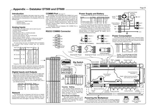
Appendix — Datataker <strong>DT500</strong> and DT600IntroductionEach model in the Datataker data logger range has a numberof characteristics that differentiate it from the other models. Thispage describes the characteristics for the Datataker 500 and theDatataker 600:• 10 analog and 7 digital channels• Network support• Channel expansion socketAnalog Inputs• 10 differential or 30 single ended, can be used in any mix.• Sampling rate 25 samples/sec• Linearity 100 MΩ selectable• Common mode range ±3.5 Vdc• Common mode rejection >90 db (110 db typical)• Series mode line rejection >35 db• Sensor excitation of 4.5V, 250.0µA or 2.500mA each channel.• Full, half and quarter bridges, voltage or current excitation.• Multiplexer type: solid state (CMOS)For each analog input type, the Datataker 500 and Datataker600 provides three decade ranges that are selectedautomatically:Input Type Channels Range Units Reso- AccuracyDE SE lution at 25°CDC Voltage 10 30 ±25 mV 1µV 0.11%±250 mV 10µV 0.11%±2500 mV 100µV 0.11%DC Current 10 40 ±0.25 mA 200nA 0.21%±2.5 mA 1µA 0.21%±25. mA 10µA 0.21%Resistance 10 20 10 Ohms 0.5mΩ 0.20%100 Ohms 5mΩ 0.10%500 Ohms 50mΩ 0.20%7000 Ohms 500mΩ 0.3%Frequency 10 30 0.1-20,000 Hz 0.01% 0.05%DE refers to double ended or differential channels and SE refersto single ended channels (see Glossary on page 23). Accuracy isexpressed as percentage of reading at 25°C (see page 17).Digital Inputs and Outputs• 4 TTL/CMOS compatible digital input channels for digital state,digital events, low speed counters (10 Hz, 16 bit, presettable).Digital input terminals are shared with digital output channels• 4 Digital open collector outputs rated to 200mA at 30V• 3 high speed counters, (1KHz or 1MHz, 16 bit, presettable).• All analog channels may also be used as digital inputs, with auser definable threshold.Input Type Channels RangeDigital Bit 4 0 or 1 StateDigital Nibble 1 0 to 15 StateLS counter 4 65535 CountsHS counter 3 65535 CountsNetworkThe Datataker 500 and Datataker 600 both have an RS485network. A proprietary network protocol supports error freecommunications between up to thirty two Datataker 500 andDatataker 600 series data loggers. See page 14 for more details.COMMS Port also page 13The Datataker 500 and Datataker 600 COMMS Port is serialRS232 compatible. The output signal level is approximately ±4Volts, allowing communications over distances in access 100meters at 1200 baud. Greater distances are possible at 300baud. The maximum practical distance is also dependent on thehost computer's RS232 characteristics. (Note: the RS232"standard" specifies 2000pF maximum cable capacitance, andno maximum distance).The Datataker 500 and Datataker 600 COMMS Port iselectrically isolated to 500V.RS232 COMMS ConnectorAddress s4 s5 s6See "Baud Rate and Address"012345678910111213141516171819202122232425262728293031offoffoffoffoffoffoffoffoffoffoffoffoffoffoffoffononononononononononononononononN/CN/CN/CN/Coffoffoffoffoffoffoffoffononononononononoffoffoffoffoffoffoffoffonononononononon9876off offoff offoff onoff onon offon offon onon onoff offoff offoff onoff onon offon offon onon onoff offoff offoff onoff onon offon offon onon onoff offoff offoff onoff onon offon offon onon on54321s7 s8offonoffonoffonoffonoffonoffonoffonoffonoffonoffonoffonoffonoffonoffonoffonoffonN/CRxDTxDN/CInterfaceGround1 2 3 4 5 6 7 8ONCountry s1US (60Hz) onOther (50Hz) offdefault+DC–11-24Vdc~~GndExternal DC PowerDip SwitchShown set to thefactory settingCountry SettingThe Country Setting determines thedefault integration period (16.7mS for USand 20mS for others) for the analog todigital converter, and the default dateformat (see "Date" on page 6).Baud Rate and AddressDip switch position four (s4) is notavailable for setting the address if 300 or9600 baud rate is selected. This reducesthe address range to 0 – 15.Power Supply and BatteryThe Datataker 500 and 600 can be powered as follows:Source Range +Terminal –TerminalAC 9 – 18Vac AC/DC~ AC/DC~DC 11 – 24Vdc AC/DC~ Gnd9V Alkaline Battery 6.2 – 10Vdc Alkaline + Bat. –6V Gel Cell Battery 5.6 – 8Vdc Lead + Bat. –The gel cell connection provides temperature compensatedcharging with voltage (6.90V) and current (1A) limiting for athree cell battery, when an AC or DC supply is also connected.It is not recommended to connect both an internal and anexternal battery. If two batteries are required it is better that theexternal battery is a larger capacity 12V battery, and isconnected as External DC Power.6V–+Internal Gel Cell Battery~9-18VacBaud Rate s2 s3 s4 Add. Range110 mm1200960030024004800offoffoffononoffononoffonxoffon0 - 310 - 150 - 150 - 31xx 0 - 31x = don't care1 Alkaline +2 Bat. –3 Lead +~~GndExternal AC Power+–9VRS232 COMMSPort (Isolated)ON1 23 4 5 6 7 8Net.Ground– +1 2 3AC/DC1 Alkaline +2 Bat. –3 Lead +Internal Alkaline Battery+–Bat. +Bat. –External Battery(6-9V Gel Cell or 9V Alkaline)ExternalBattery~~ – +WakeInternal BatteryConnectorMemory Card SocketConvert+5 voltsLamp(switched)AC/DCPowerDigitalI/O4 3- +* R -2-1-4 3 2 1 3 2 1 R + +* R +* R *Channel ExpansionConnectorHeight: without memory card 85mmwith memory card 105mm+ + + + + +* - R * - R * - R * - R * - R * - R10Ground~~External BatteryConnectionsBat +Bat –GndCounters91(out)Single Ended Ref.250 mm270 mmPowering the MultiplexerThe Datataker 500 and 600 have an option to maintain multiplexerpower in low power mode. This is achieved by moving the Mux. Powerlink located under the top cover near channel 9, as shown on the right.8ProtectionCircuitAnalog Channels76Analog Channels5DisplayConnectorPage 25Power ConsumptionThe <strong>DT500</strong> and 600 will use little power if allowed to sleep.Less power is consumed if the logger is powered via the batteryterminals, rather than the AC/DC terminals, because the batterycharger circuit draws additional current.Power Source Condition Current (typical)battery awake 100mAbattery sleep 0.36mAAC/DC awake 105mAAC/DC awake & charging 600mAAC/DC sleep 5mAAC/DC sleep & charging 500mACaution - To avoid damage use 6Voltlead acid battery only, ensure correctpolarity before connecting the batterySW USWMux PowerPower-downPosition6.9V Switch ModeRegulator(–9.2mV/°C)1000µF0.22Ω6.9VLead +Bat. –Gnd.SW USWMux PowerPower maintainedPositionAlkaline +75mm
Appendix — Datataker DT505 and DT605Page 26IntroductionEach model in the Datataker data logger range has a numberof characteristics which differentiates it from theeother models.This page describes the characteristics for the Datataker 505 andthe Datataker 605:• 10 analog and 7 digital channels• Relay Multiplexer (±100V input)• Network support (as for <strong>DT500</strong>/600)• Channel expansion socketAnalog Inputs• 10 differential or 30 single ended, or any mix.• Switchable attenuator that allows high voltage measurement.• Sampling rate 25 samples/sec.• Channels have 500 volt isolation while not being read.• Input impedance 1MΩ, or >100 MΩ selectable.• Common mode range ±3.5 Vdc, ±100 Vdc attenuators on.• Common mode rejection >90 db (110 db typical).• Series mode line rejection >35 db.• Sensor excitation of 4.5V, 250.0µA or 2.500mA each channel.• Full, half and quarter bridges, voltage or current excitation.• Multiplexer type: relayInput Type Channels Range Units Reso- AccuracyDE SE lution at 25°CDC Voltage 10 30 ±25 mV 1µV 0.11%±250 mV 10µV 0.11%±2500 mV 100µV 0.11%±7 V 250µV 0.31%±70V 2.5mV 0.31%±100V 25mV 0.31%DC Current 10 40 ±0.25 mA 200nA 0.21%±2.5 mA 1µA 0.21%±25. mA 10µA 0.21%Resistance 10 20 10 Ohms 0.5mΩ 0.20%100 Ohms 5mΩ 0.10%500 Ohms 50mΩ 0.20%7000 Ohms 500mΩ 0.30%Frequency 10 30 0.1-20,000 Hz 0.01% 0.05%DE refers to double ended or differential channels and SE refersto single ended channels (see Glossary on page 23). Accuracy isexpressed as percentage of reading at 25°C (see page 17).All analog input channel terminals except for the Return (R)terminals are capable of withstanding 1.5KV for 10µS, 500V for50mS and 100V indefinitely. The return terminal can withstandonly 5% of these voltages.These withstanding voltages only apply to unselectedchannels. While a channel is actually being read (a process thattypically takes 30mS), these withstanding voltages are reducedto that of the return terminal.Digital Inputs and Outputs• 4 TTL/CMOS compatible digital input channels for digital state,digital events, low speed counters (10 Hz, 16 bit, presettable).Digital input terminals are shared with digital output channels• 4 Digital open collector outputs rated to 200mA at 30V• 3 high speed counters, (1KHz or 1MHz, 16 bit, presettable).• All analog channels may also be used as digital inputs, with auser definable threshold.Input Type Channels RangeDigital Bit 4 0 or 1 StateDigital Nibble 1 0 to 15 StateLS counter 4 65535 CountsHS counter 3 65535 CountsCOMMS Port also page 13The Datataker 505 and Datataker 605 COMMS Port is serialRS232 compatible. The output signal level is approximately ±4Volts, allowing communications over distances in access 100meters at 1200 baud. Greater distances are possible at 300baud. The maximum practical distance is also dependent on thehost computer's RS232 characteristics. (Note: the RS232"standard" specifies 2000pF maximum cable capacitance, andno maximum distance).The Datataker 505 and Datataker 605 COMMS Port iselectrically isolated to 500V.RS232 COMMS ConnectorAddress s4 s5 s6See "Baud Rate and Address"012345678910111213141516171819202122232425262728293031offoffoffoffoffoffoffoffoffoffoffoffoffoffoffoffononononononononononononononononN/CN/CN/CN/Coffoffoffoffoffoffoffoffononononononononoffoffoffoffoffoffoffoffonononononononon9876off offoff offoff onoff onon offon offon onon onoff offoff offoff onoff onon offon offon onon onoff offoff offoff onoff onon offon offon onon onoff offoff offoff onoff onon offon offon onon on54321s7 s8offonoffonoffonoffonoffonoffonoffonoffonoffonoffonoffonoffonoffonoffonoffonoffonN/CRxDTxDN/CInterfaceGround1 2 3 4 5 6 7 8defaultdefaultON+DC–11-24Vdc~~GndExternal DC PowerCountry s1US (60Hz) on defaultOther (50Hz) offBaud Rate s21200960030024004800offoffoffononDip switchShown set to thefactory settings3 s4 Add. RangeoffononoffonxoffonxxPower Supply and BatteryThe Datataker 505 and 605 can be powered as follows:Source Range + Terminal – TerminalAC 9 – 18Vac AC/DC~ AC/DC~DC 11 – 24Vdc AC/DC~ Gnd9V Alkaline Battery 6.2 – 10Vdc Alkaline + Bat. –6V Gel Cell Battery 5.6 – 8Vdc Lead + Bat. –The gel cell connection provides temperature compensatedcharging with voltage (6.90V) and current (1A) limiting for athree cell battery, when an AC or DC supply is also connected.It is not recommended to connect both an internal and anexternal battery. If two batteries are required it is better that theexternal battery is a larger capacity 12V battery, and isconnected as External DC Power.The simplified schematic on page 25 for the Datataker 500and 600 is also applicable to the Datataker 505 and 605.0 - 310 - 150 - 150 - 310 - 31x = don't careCountry SettingThe Country Setting determines thedefault integration period (16.7mS for USand 20mS for others) for the analog todigital converter, and the default dateformat (see "Date" on page 6).Baud Rate and AddressDip switch position four (s4) is notavailable for setting the address if 300 or9600 baud rate is selected. This reducesthe address range to 0 – 15.110 mm~9–18Vac~~GndExternal AC PowerRS232 COMMSPort (Isolated)ON1 23 4 5 6 7 86V Gel Cell or9V Alkaline)+–Net.– +1 2 3GroundBat. +Bat. –External BatteryAC/DCExternalBattery~~ – +WakeInternal BatteryConnectorMemory Card SocketConvert+5 voltsLamp(switched)Power ConsumptionThe Datataker 505 and 605 will consume very little power ifit is allowed to sleep. Less power is consumed if the logger ispowered via the battery terminals rather than the AC/DC Powerterminals. This is because the battery charger circuit drawsadditional current.DigitalI/O4 3- +* R -2-1-4 3 2 1 3 2 1 R + +* R +* R *Channel ExpansionConnectorHeight: without memory card 85mmwith memory card 105mm+ + + + + +* - R * - R * - R * - R * - R * - R10GroundCounters91(out)Single Ended Ref.High Voltage MeasurementThe Datataker 505 and 605 models have a switchablefour wire (on the ★, +, – and SERef. lines) attenuator afterthe input multiplexer. In each case attenuation is relative toground. The attenuators on the differential inputs (+ and –)are matched to ensure high common mode rejection.By default two channel types automatically switch in theattenuators – n HV and n L. See "Channel Types" on page4 for more details. For other channel types use the Achannel option to switch in the attenuators e.g 2AS(A). See"Channel Options" on page 5.ON12 3 4Power Source Condition Current (typical)battery awake 220mAbattery sleep 0.36mAAC/DC awake 230mAAC/DC awake & charging 600mAAC/DC sleep 5mAAC/DC sleep & charging 400mABattery life for the Datataker 505 and 605 is about one thirdlonger than that of the Datataker 500 and 600 for slow scanrates (i.e. >30 minutes). See "Battery Life" on page 15.6V–+Internal Gel Cell Battery250 mm270 mm81 Alkaline +2 Bat. –3 Lead +Analog Channels76+–9VAnalog Channels51 Alkaline +2 Bat. –3 Lead +Internal Alkaline BatteryDisplayConnectorAuxiliary Dip SwitchThe four way Auxilliary Dip Switch providesadditional versatility.1 2 3 4Default positionsfor SW2 dip switchONHeadphone Socket(Geologger versions)Reserved: must be set indefault position otherwisenetwork operation will beimpaired.75mmWith s4 in the ON position a19200 Hz frequency signal isapplied to the High SpeedCounter (1HSC) input.