UM-0046-A0 - DT500 Concise Users Manual - dataTaker
UM-0046-A0 - DT500 Concise Users Manual - dataTaker
UM-0046-A0 - DT500 Concise Users Manual - dataTaker

You also want an ePaper? Increase the reach of your titles
YUMPU automatically turns print PDFs into web optimized ePapers that Google loves.
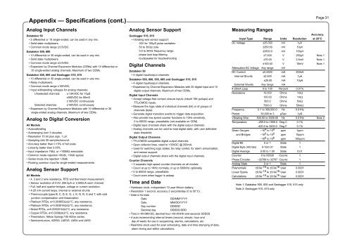
Appendix — Specifications (cont.)Analog Input ChannelsDatataker 50• 5 differential or 10 single-ended, can be used in any mix.• Solid state multiplexers.• Common mode range ±3.5VDC.Datataker 500, 600• 10 differential or 30 single-ended, can be used in any mix.• Solid state multiplexers.• Common mode range ±3.5VDC.• Expansion by Channel Expansion Modules (CEMs) with 10 differential or30 single-ended analog channels. Maximum of two CEMs.Datataker 505, 605 and Geologger 515, 615• 10 differential or 30 single-ended, can be used in any mix.• Relay multiplexers.• Common mode range ±100VDC.• Input withstanding voltages for analog channels:Unselected channels ±1.5KVDC for 10µS±500VDC for 50mS±100VDC continuouslySelected channels ±100VDC continuously• Expansion by Channel Expansion Modules with 10 differential or 30single-ended analog channels. Maximum of two CEMs.Analog to Digital ConversionAll Models• Autocalibrating• Autoranging over 3 decades.• Resolution 15 bit plus sign, 1 µV.• Sampling rate 25 samples/second.• Accuracy better than 0.15% of full scale.• Linearity better than 0.05%• Input impedance 1MΩ, or >100MΩ selectable.• Common mode rejection >90db, 110db typical.• Series mode line rejection >35db• Floating common input for single-ended measurements.Analog Sensor SupportAll Models• 4, 3 and 2 wire resistance, RTD and thermistor measurement.• Sensor excitation of 4.5V, 250.0µA or 2.500mA each channel.• Full, half and quarter bridges, voltage or current excitation.• 4-20 mA current loops, internal or external shunts• Thermocouple types B, C, D, E, G, J, K, N, R, S and T, with coldjunction compensation and linearization.• Platinum RTDs, a=0.003850Ω/Ω/°C, any resistance.• Platinum RTDs, a=0.003916Ω/Ω/°C, any resistance.• Nickel RTDs, a=0.005001Ω/Ω/°C, any resistance.• Copper RTDs, a=0.0039Ω/Ω/°C, any resistance.• Thermistors, Yellow Springs YSI 400xx series.• Semiconductors, AD590, LM335, LM34 and LM35.Analog Sensor SupportGeologger 515, 615• Vibrating wire sensor support:30V for 100µS pulse excitation50 to 300Ω coils0.5 to 5KHz frequency rangephase lock loop filteringloudspeaker for troubleshootingDigital ChannelsDatataker 50• 5 digital input/output channels.Datataker 500, 600, 505, 605 and Geologger 515, 615• 4 digital input/output channels.• Expansion by Channel Expansion Modules with 20 digital input and 10digital output channels. Maximum of two CEMs.Digital Input Channels• Accept voltage-free contact closure inputs (inbuilt 15K pullups) andTTL/CMOS inputs.• Measure the logic state of individual channels (bit) or of groups ofchannels (byte).• Generate digital transition events to trigger data acquisition.• Also provide low speed counter functions to 10Hz sensitivity,0 to 65535 range, presettable (not available on CEM).• Digital input channels share with the digital output channels.• Analog channels can be used to read digital state, with user definablestate threshold.Digital Output Channels• TTL/CMOS-compatible digital output channels.• Open collector lines, rated to +30VDC @ 200mA.• Used for switching logic states, for relay control, for alarm annunciation,and sensor support.• Digital output channels share with the digital input channels.Counter Channels• 3 separate high speed counter channels on all models.• Count at up to 1KHz normally, or up to 500KHz optionally.• 0 to 65535 range, presettable.• Count even when logger is asleepTime and Date• Hardware clock, independent 10 year lithium battery.• Resolution 1 second, accuracy 2 seconds/day (0 to 50°C).• Date in formatsDateDD/MM/YYYYDateMM/DD/YYYYDay numberDDDDDDecimal dayDDDDD.DDD• Time in HH:MM:SS, decimal hour HH.HHHH and seconds SSSSS• 4 auto-incrementing internal timers (second, minute, hour andday of week) for use in sequencing, alarms, calculations, etc.• Real-time clock used for scan scheduling, date and time stamping of data,alarm timing and within calculations.Measuring RangesPage 31AccuracyInput Type Range Units Resolution at 25°CDC Voltage ±25.000 mV 1µV±250.00 mV 10µV±2500.0 mV 100µV±7.000 V 250µV Note 1±70.00 V 2.5mV Note 1±100.00 V 10mV Note 1Attenuated DC Voltage Any range mVDC Current ±0.2500 mA 200nAInternal Shunts ±2.500 mA 1µA±25.00 mA 10µAExternal Shunts Any range mA4-20mA Loop 0 to 100 Percent 0.01%Resistance 10.000 Ohms 1mΩ100.00 Ohms 1mΩ500.0 Ohms 5mΩ7000.0 Ohms 50mΩFrequency 0.1 to 300,000.0 Hz 0.01HzPeriod 30,000 to 3 µSec 1µSVibrating Wire 500.00 to 5000.00 Hz 0.01Hz Note 2Temperature –250.0 to 1800.0 Deg C 0.1%-420.0 to 3200.0 Deg F 0.1%Strain Gauges –10 4 to 10 4 ppm 1ppmand Bridges –10 5 to 10 5 ppm 10ppm–10 6 to 10 6 ppm 100ppmDigital Bit 0 or 1 State 1Digital Byte (4/5 bits) 0-15/0-31 State 1Digital Average 0.00 to 1.00 State 0.01Counter 0 to 65535 Counts 1Phase Encoder –32768 to 32767 Counts 1Analog State 0 or 1 State 1Polynomials ±9.9e -18 to ±9.9e 18 User 0.0001Linear Spans ±9.9e -18 to ±9.9e 18 User 0.0001Calculations ±9.9e -18 to ±9.9e 18 User 0.0001Note 1: Datataker 505, 605 and Geologger 515, 615 onlyNote 2: Geologger 515, 615 only