FCU 2165/2175 Reference Manual - Emerson Process Management
FCU 2165/2175 Reference Manual - Emerson Process Management
FCU 2165/2175 Reference Manual - Emerson Process Management
- No tags were found...
Create successful ePaper yourself
Turn your PDF publications into a flip-book with our unique Google optimized e-Paper software.
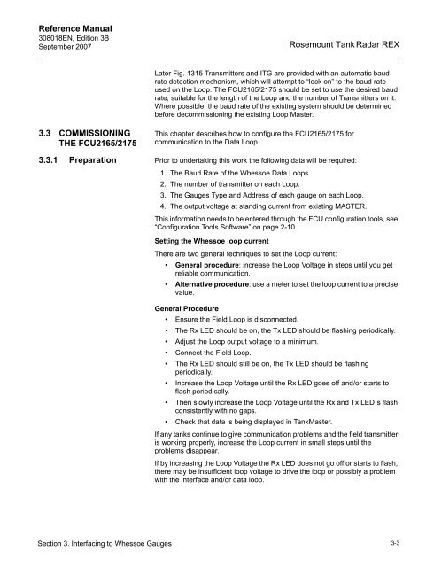
<strong>Reference</strong> <strong>Manual</strong>308018EN, Edition 3BSeptember 2007Rosemount Tank Radar REXLater Fig. 1315 Transmitters and ITG are provided with an automatic baudrate detection mechanism, which will attempt to “lock on” to the baud rateused on the Loop. The <strong>FCU</strong><strong>2165</strong>/<strong>2175</strong> should be set to use the desired baudrate, suitable for the length of the Loop and the number of Transmitters on it.Where possible, the baud rate of the existing system should be determinedbefore decommissioning the existing Loop Master.3.3 COMMISSIONINGTHE <strong>FCU</strong><strong>2165</strong>/<strong>2175</strong>This chapter describes how to configure the <strong>FCU</strong><strong>2165</strong>/<strong>2175</strong> forcommunication to the Data Loop.3.3.1 Preparation Prior to undertaking this work the following data will be required:1. The Baud Rate of the Whessoe Data Loops.2. The number of transmitter on each Loop.3. The Gauges Type and Address of each gauge on each Loop.4. The output voltage at standing current from existing MASTER.This information needs to be entered through the <strong>FCU</strong> configuration tools, see“Configuration Tools Software” on page 2-10.Setting the Whessoe loop currentThere are two general techniques to set the Loop current:• General procedure: increase the Loop Voltage in steps until you getreliable communication.• Alternative procedure: use a meter to set the loop current to a precisevalue.General Procedure• Ensure the Field Loop is disconnected.• The Rx LED should be on, the Tx LED should be flashing periodically.• Adjust the Loop output voltage to a minimum.• Connect the Field Loop.• The Rx LED should still be on, the Tx LED should be flashingperiodically.• Increase the Loop Voltage until the Rx LED goes off and/or starts toflash periodically.• Then slowly increase the Loop Voltage until the Rx and Tx LED´s flashconsistently with no gaps.• Check that data is being displayed in TankMaster.If any tanks continue to give communication problems and the field transmitteris working properly, increase the Loop current in small steps until theproblems disappear.If by increasing the Loop Voltage the Rx LED does not go off or starts to flash,there may be insufficient loop voltage to drive the loop or possibly a problemwith the interface and/or data loop.Section 3. Interfacing to Whessoe Gauges3-3


