Pulse XT 25e Manual - E-flite
Pulse XT 25e Manual - E-flite
Pulse XT 25e Manual - E-flite
- No tags were found...

You also want an ePaper? Increase the reach of your titles
YUMPU automatically turns print PDFs into web optimized ePapers that Google loves.
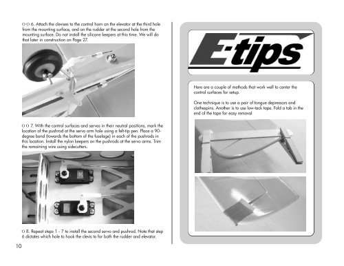
Ο Ο 6. Attach the clevises to the control horn on the elevator at the third holefrom the mounting surface, and on the rudder at the second hole from themounting surface. Do not install the silicone keepers at this time. We will dothat later in construction on Page 27.Here are a couple of methods that work well to center thecontrol surfaces for setup.One technique is to use a pair of tongue depressors andclothespins. Another is to use low-tack tape. Fold a tab in theend of the tape for easy removalΟ Ο 7. With the control surfaces and servos in their neutral positions, mark thelocation of the pushrod at the servo arm hole using a felt-tip pen. Place a 90-degree bend (towards the bottom of the fuselage) in each of the pushrods inthis location. Install the nylon keepers on the pushrods at the servo arms. Trimthe remaining wire using sidecutters.10Ο 8. Repeat steps 1 - 7 to install the second servo and pushrod. Note that step6 dictates which hole to hook the clevis to for both the rudder and elevator.