SECTION 1 SINGLE-SUPPLY AMPLIFIERS - Analog Devices
SECTION 1 SINGLE-SUPPLY AMPLIFIERS - Analog Devices
SECTION 1 SINGLE-SUPPLY AMPLIFIERS - Analog Devices
- No tags were found...
Create successful ePaper yourself
Turn your PDF publications into a flip-book with our unique Google optimized e-Paper software.
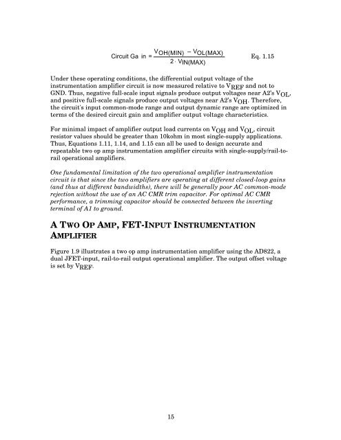
Circuit Ga in = V OH(MIN) – V OL(MAX)2 ⋅ VIN(MAX)Eq. 1.15Under these operating conditions, the differential output voltage of theinstrumentation amplifier circuit is now measured relative to V REF and not toGND. Thus, negative full-scale input signals produce output voltages near A2’s V OL ,and positive full-scale signals produce output voltages near A2’s V OH . Therefore,the circuit's input common-mode range and output dynamic range are optimized interms of the desired circuit gain and amplifier output voltage characteristics.For minimal impact of amplifier output load currents on V OH and V OL , circuitresistor values should be greater than 10kohm in most single-supply applications.Thus, Equations 1.11, 1.14, and 1.15 can all be used to design accurate andrepeatable two op amp instrumentation amplifier circuits with single-supply/rail-torailoperational amplifiers.One fundamental limitation of the two operational amplifier instrumentationcircuit is that since the two amplifiers are operating at different closed-loop gains(and thus at different bandwidths), there will be generally poor AC common-moderejection without the use of an AC CMR trim capacitor. For optimal AC CMRperformance, a trimming capacitor should be connected between the invertingterminal of A1 to ground.A TWO OP AMP, FET-INPUT INSTRUMENTATIONAMPLIFIERFigure 1.9 illustrates a two op amp instrumentation amplifier using the AD822, adual JFET-input, rail-to-rail output operational amplifier. The output offset voltageis set by V REF .15


