SECTION 1 SINGLE-SUPPLY AMPLIFIERS - Analog Devices
SECTION 1 SINGLE-SUPPLY AMPLIFIERS - Analog Devices
SECTION 1 SINGLE-SUPPLY AMPLIFIERS - Analog Devices
- No tags were found...
You also want an ePaper? Increase the reach of your titles
YUMPU automatically turns print PDFs into web optimized ePapers that Google loves.
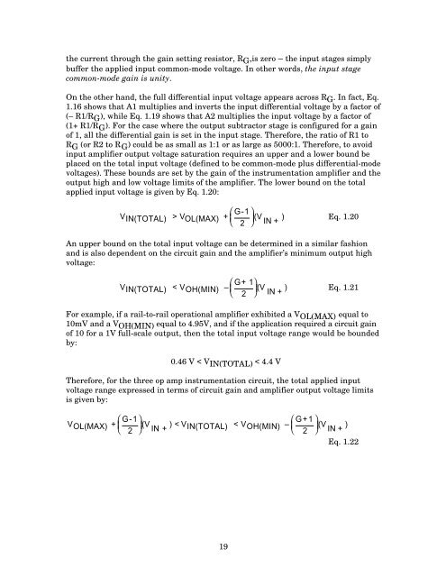
the current through the gain setting resistor, R G ,is zero – the input stages simplybuffer the applied input common-mode voltage. In other words, the input stagecommon-mode gain is unity.On the other hand, the full differential input voltage appears across R G . In fact, Eq.1.16 shows that A1 multiplies and inverts the input differential voltage by a factor of(– R1/R G ), while Eq. 1.19 shows that A2 multiplies the input voltage by a factor of(1+ R1/R G ). For the case where the output subtractor stage is configured for a gainof 1, all the differential gain is set in the input stage. Therefore, the ratio of R1 toR G (or R2 to R G ) could be as small as 1:1 or as large as 5000:1. Therefore, to avoidinput amplifier output voltage saturation requires an upper and a lower bound beplaced on the total input voltage (defined to be common-mode plus differential-modevoltages). These bounds are set by the gain of the instrumentation amplifier and theoutput high and low voltage limits of the amplifier. The lower bound on the totalapplied input voltage is given by Eq. 1.20:⎛V IN(TOTAL) > V OL(MAX) + G-1 ⎞⎜ ⎟ (V ) Eq. 1.20⎝ 2 ⎠ IN +An upper bound on the total input voltage can be determined in a similar fashionand is also dependent on the circuit gain and the amplifier’s minimum output highvoltage:⎛V IN(TOTAL) < V OH(MIN) – G+ 1 ⎞⎜ ⎟ (V ) Eq. 1.21⎝ 2 ⎠ IN +For example, if a rail-to-rail operational amplifier exhibited a V OL(MAX) equal to10mV and a V OH(MIN) equal to 4.95V, and if the application required a circuit gainof 10 for a 1V full-scale output, then the total input voltage range would be boundedby:0.46 V < V IN(TOTAL) < 4.4 VTherefore, for the three op amp instrumentation circuit, the total applied inputvoltage range expressed in terms of circuit gain and amplifier output voltage limitsis given by:⎛V OL(MAX) + G-1 ⎞⎛(V ) < V2 IN + IN(TOTAL) < V OH(MIN) – G+1 ⎞⎜ ⎟⎜ ⎟ (V )⎝ ⎠⎝ 2 ⎠ IN +Eq. 1.2219


