SECTION 1 SINGLE-SUPPLY AMPLIFIERS - Analog Devices
SECTION 1 SINGLE-SUPPLY AMPLIFIERS - Analog Devices
SECTION 1 SINGLE-SUPPLY AMPLIFIERS - Analog Devices
- No tags were found...
Create successful ePaper yourself
Turn your PDF publications into a flip-book with our unique Google optimized e-Paper software.
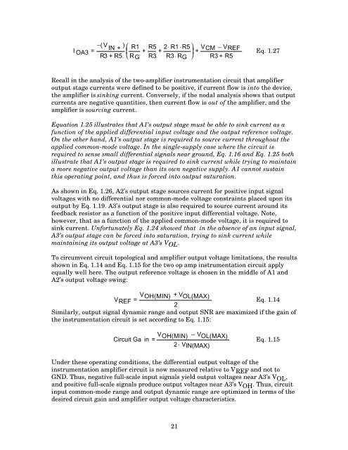
I OA3 =−(V IN +) ⎛ R13 + R5 RG + R5 2⋅ R1 ⋅R5⎞+R3 R3 RG + V CM − VREF⎜⎟R ⎝⋅ ⎠ R3 + R5Eq. 1.27Recall in the analysis of the two-amplifier instrumentation circuit that amplifieroutput stage currents were defined to be positive, if current flow is into the device,the amplifier is sinking current. Conversely, if the nodal analysis shows that outputcurrents are negative quantities, then current flow is out of the amplifier, and theamplifier is sourcing current.Equation 1.25 illustrates that A1’s output stage must be able to sink current as afunction of the applied differential input voltage and the output reference voltage.On the other hand, A1’s output stage is required to source current throughout theapplied common-mode voltage. In the single-supply case where the circuit isrequired to sense small differential signals near ground, Eq. 1.16 and Eq. 1.25 bothillustrate that A1’s output stage is required to sink current while trying to maintaina more negative output voltage than its own negative supply. A1 cannot sustainthis operating point, and thus is forced into output saturation.As shown in Eq. 1.26, A2’s output stage sources current for positive input signalvoltages with no differential nor common-mode voltage constraints placed upon itsoutput by Eq. 1.19. A3’s output stage is also required to source current around itsfeedback resistor as a function of the positive input differential voltage. Note,however, that as a function of the applied common-mode voltage, it is required tosink current. Unfortunately Eq. 1.24 showed that in the absence of an input signal,A3’s output stage can be forced into saturation, trying to sink current whilemaintaining its output voltage at A3’s V OL .To circumvent circuit topological and amplifier output voltage limitations, the resultsshown in Eq. 1.14 and Eq. 1.15 for the two op amp instrumentation circuit applyequally well here. The output reference voltage is chosen in the middle of A1 andA2’s output voltage swing:V REF = V OH(MIN) + V OL(MAX)Eq. 1.142Similarly, output signal dynamic range and output SNR are maximized if the gain ofthe instrumentation circuit is set according to Eq. 1.15:Circuit Ga in = V OH(MIN) – V OL(MAX)2 ⋅ VIN(MAX)Eq. 1.15Under these operating conditions, the differential output voltage of theinstrumentation amplifier circuit is now measured relative to V REF and not toGND. Thus, negative full-scale input signals yield output voltages near A3’s V OL ,and positive full-scale signals produce output voltages near A3’s V OH . Thus, circuitinput common-mode range and output dynamic range are optimized in terms of thedesired circuit gain and amplifier output voltage characteristics.21


