
You also want an ePaper? Increase the reach of your titles
YUMPU automatically turns print PDFs into web optimized ePapers that Google loves.
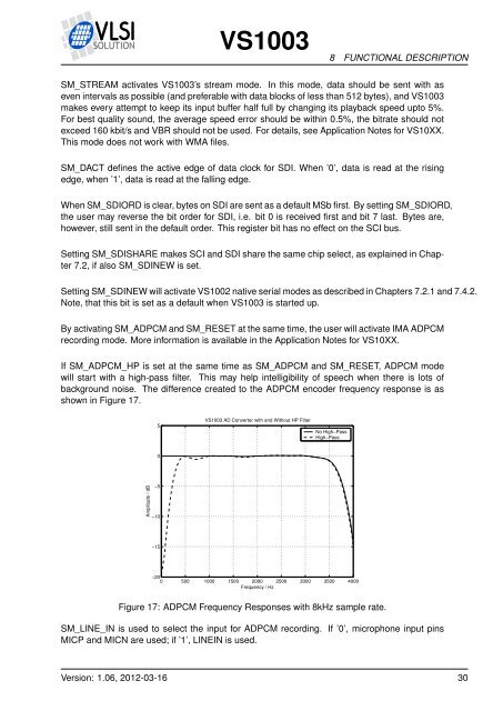
<strong>VS1003</strong>8 FUNCTIONAL DESCRIPTIONSM_STREAM activates <strong>VS1003</strong>’s stream mode. In this mode, data should be sent with aseven intervals as possible (and preferable with data blocks of less than 512 bytes), and <strong>VS1003</strong>makes every attempt to keep its input buffer half full by changing its playback speed upto 5%.For best quality sound, the average speed error should be within 0.5%, the bitrate should notexceed 160 kbit/s and VBR should not be used. For details, see Application Notes for VS10XX.This mode does not work with WMA files.SM_DACT defines the active edge of data clock for SDI. When ’0’, data is read at the risingedge, when ’1’, data is read at the falling edge.When SM_SDIORD is clear, bytes on SDI are sent as a default MSb first. By setting SM_SDIORD,the user may reverse the bit order for SDI, i.e. bit 0 is received first and bit 7 last. Bytes are,however, still sent in the default order. This register bit has no effect on the SCI bus.Setting SM_SDISHARE makes SCI and SDI share the same chip select, as explained in Chapter7.2, if also SM_SDINEW is set.Setting SM_SDINEW will activate VS1002 native serial modes as described in Chapters 7.2.1 and 7.4.2.Note, that this bit is set as a default when <strong>VS1003</strong> is started up.By activating SM_ADPCM and SM_RESET at the same time, the user will activate IMA ADPCMrecording mode. More information is available in the Application Notes for VS10XX.If SM_ADPCM_HP is set at the same time as SM_ADPCM and SM_RESET, ADPCM modewill start with a high-pass filter. This may help intelligibility of speech when there is lots ofbackground noise. The difference created to the ADPCM encoder frequency response is asshown in Figure 17.5<strong>VS1003</strong> AD Converter with and Without HP FilterNo High−PassHigh−Pass0Amplitude / dB−5−10−15−200 500 1000 1500 2000 2500 3000 3500 4000Frequency / HzFigure 17: ADPCM Frequency Responses with 8kHz sample rate.SM_LINE_IN is used to select the input for ADPCM recording. If ’0’, microphone input pinsMICP and MICN are used; if ’1’, LINEIN is used.Version: 1.06, 2012-03-16 30