- Page 1: Emotron FDU 2.0AC driveInstruction
- Page 5 and 6: Safety InstructionsInstruction manu
- Page 7 and 8: ContentsSafety Instructions .......
- Page 9 and 10: 1. IntroductionEmotron FDU is used
- Page 11 and 12: Table 1StandardsEuropeanAllUSAMarke
- Page 13 and 14: 2. MountingThis chapter describes h
- Page 15 and 16: Ø 7 (4x)128,524,830 160Ø 13 (2x)5
- Page 17 and 18: 2.3 Cabinet mounting2.3.1 CoolingIf
- Page 19 and 20: 3. InstallationThe description of i
- Page 21 and 22: Switches between the motor and theA
- Page 23 and 24: 2 5 A2 31 L1 3 L2 5 L32 0-ÜÜÜÜ
- Page 25 and 26: 3.5.1 Dimension of cables and fuses
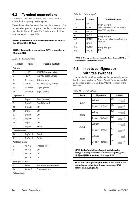
- Page 27: 4. Control Connections4.1 Control b
- Page 31 and 32: NOTE: The screening of control sign
- Page 33 and 34: 5. Getting StartedThis chapter is a
- Page 35 and 36: 5.4 Local controlManual control via
- Page 37 and 38: 6. ApplicationsThis chapter contain
- Page 39 and 40: 7. Main FeaturesThis chapter contai
- Page 41 and 42: 7.1.6 Preset referencesThe AC drive
- Page 43 and 44: Run Inputs Level-controlled.The inp
- Page 45 and 46: .Torque [%][4161] MaxAlarmMar (15%)
- Page 47 and 48: 7.6.2 Fixed MASTERThis is the defau
- Page 49 and 50: 7.6.6 PID controlWhen using the Pum
- Page 51 and 52: 7.6.8 Checklist And Tips1. Main Fun
- Page 53 and 54: Stopping an additional pumpThis fig
- Page 55 and 56: 8. EMC and Machine Directive8.1 EMC
- Page 57 and 58: 9. Operation via the Control PanelT
- Page 59 and 60: Add a menu to the toggle loop1. Go
- Page 61 and 62: 500 Inputs/Outputs and VirtualConne
- Page 63 and 64: 10. Serial communicationThe AC driv
- Page 65 and 66: 10.6 Description of the EIntformats
- Page 67 and 68: 11. Functional DescriptionThis chap
- Page 69 and 70: Select Motor [212]This menu is used
- Page 71 and 72: Local/Remote key function [217]The
- Page 73 and 74: 11.2.4 Motor Data [220]In this menu
- Page 75 and 76: Motor ventilation [228]Parameter fo
- Page 77 and 78: Motor PWM [22E]Menus for advanced s
- Page 79 and 80:
10000010000t [s]10001000 s (120%)10
- Page 81 and 82:
Motor PTC [237]In this menu the int
- Page 83 and 84:
Copy All Settings to Control Panel
- Page 85 and 86:
Overvolt D [253]Delay time starts c
- Page 87 and 88:
Communication informationModbus Ins
- Page 89 and 90:
Min Alarm [25K]Delay time starts co
- Page 91 and 92:
External Motor Trip Type [25S]Selec
- Page 93 and 94:
Read/Write [2633]Select read/write
- Page 95 and 96:
11.3 Process and ApplicationParamet
- Page 97 and 98:
User-defined Unit [323]This menu is
- Page 99 and 100:
F(Value), Process Max [328]This fun
- Page 101 and 102:
Acceleration Time to Minimum Speed[
- Page 103 and 104:
Communication informationModbus Ins
- Page 105 and 106:
Release Speed [33D]The release spee
- Page 107 and 108:
11.3.5 Speed [340]Menu with all par
- Page 109 and 110:
Jog Speed [348]The Jog Speed functi
- Page 111 and 112:
Maximum power [355]Sets maximum pow
- Page 113 and 114:
+11.3.8 PID Process Control [380]Th
- Page 115 and 116:
PID Steady State Test [388]In appli
- Page 117 and 118:
Change Condition [394]This paramete
- Page 119 and 120:
Stop Delay [39A]This delay time mus
- Page 121 and 122:
Communication informationModbus Ins
- Page 123 and 124:
Ramp Alarm [413]This function inhib
- Page 125 and 126:
Min Pre Alarm [418]Min Pre Alarm Ma
- Page 127 and 128:
Communication informationModbus Ins
- Page 129 and 130:
11.5 I/Os and VirtualConnections [5
- Page 131 and 132:
100 %n2-10 V4-20 mACommunication in
- Page 133 and 134:
Example:Process sensor is a sensor
- Page 135 and 136:
AnIn4 Set-up [51B]Same functions as
- Page 137 and 138:
Additional digital inputs [529] to
- Page 139 and 140:
AnOut1 Bipol [5333]Automatically di
- Page 141 and 142:
Communication informationModbus Ins
- Page 143 and 144:
Digital Out 2 [542]Relay 2 [552]NOT
- Page 145 and 146:
Virtual Connection 1 Source [562]Wi
- Page 147 and 148:
ExampleCreate automatic RUN/STOP si
- Page 149 and 150:
No. Description Hysteresis Window12
- Page 151 and 152:
Analogue Comparator 2,Level High [6
- Page 153 and 154:
Analogue Comparator 3, Polar [6135]
- Page 155 and 156:
Digital Comparator 3 [6153]Function
- Page 157 and 158:
Y Operator 1 [622]Selects the first
- Page 159 and 160:
11.6.4 Timer1 [640]The Timer functi
- Page 161 and 162:
Timer 2 Mode [652]652 Timer2 ModeSt
- Page 163 and 164:
Communication informationModbus Ins
- Page 165 and 166:
Fieldbusintegervalue0 No Error1 Mot
- Page 167 and 168:
I/O board Status [728] - [72A]Indic
- Page 169 and 170:
11.8 View Trip Log [800]Main menu w
- Page 171 and 172:
11.9 System Data [900]Main menu for
- Page 173 and 174:
12. Troubleshooting, Diagnoses and
- Page 175 and 176:
Table 31Trip condition, their possi
- Page 177 and 178:
Table 31Trip condition, their possi
- Page 179 and 180:
13. OptionsThe standard options ava
- Page 181 and 182:
Table 34Brake resistors FDU52 V typ
- Page 183 and 184:
13.10 Safe Stop optionTo realize a
- Page 185 and 186:
13.11 Output chokesOutput chokes, w
- Page 187 and 188:
14. Technical Data14.1 Electrical s
- Page 189 and 190:
Table 39Typical motor power at main
- Page 191 and 192:
14.2 General electrical specificati
- Page 193 and 194:
14.5 Dimensions and WeightsThe tabl
- Page 195 and 196:
14.7 Fuses, cable crosssectionsand
- Page 197 and 198:
14.7.2 Fuses and cable dimensionsac
- Page 199 and 200:
14.8 Control signalsTable 52Termina
- Page 201 and 202:
15. Menu ListDEFAULT100 Preferred V
- Page 203 and 204:
DEFAULTCUSTOMDEFAULTCUSTOM39N Pump
- Page 205 and 206:
DEFAULTCUSTOMDEFAULTCUSTOM6142 CA4
- Page 207 and 208:
DEFAULTCUSTOMDEFAULTCUSTOM880890876
- Page 209 and 210:
IndexAAbbreviations ...............
- Page 211 and 212:
(412) .............................
- Page 214:
Emotron AB, Mörsaregatan 12, SE-25