

Emotron FDU 2.0 AC drive
Emotron FDU 2.0 AC drive
Emotron FDU 2.0 AC drive
- No tags were found...

Create successful ePaper yourself
Turn your PDF publications into a flip-book with our unique Google optimized e-Paper software.
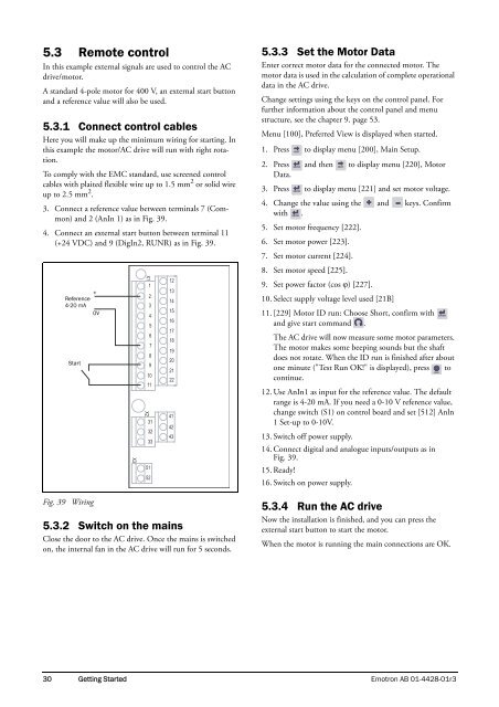
5.3 Remote controlIn this example external signals are used to control the <strong>AC</strong><strong>drive</strong>/motor.A standard 4-pole motor for 400 V, an external start buttonand a reference value will also be used.5.3.1 Connect control cablesHere you will make up the minimum wiring for starting. Inthis example the motor/<strong>AC</strong> <strong>drive</strong> will run with right rotation.To comply with the EMC standard, use screened controlcables with plaited flexible wire up to 1.5 mm 2 or solid wireup to 2.5 mm 2 .3. Connect a reference value between terminals 7 (Common)and 2 (AnIn 1) as in Fig. 39.4. Connect an external start button between terminal 11(+24 VDC) and 9 (DigIn2, RUNR) as in Fig. 39.Reference4-20 mAStartFig. 39 Wiring+0VX35.3.2 Switch on the mainsClose the door to the <strong>AC</strong> <strong>drive</strong>. Once the mains is switchedon, the internal fan in the <strong>AC</strong> <strong>drive</strong> will run for 5 seconds.X11234567891011X2313233515212131415161718192021224142435.3.3 Set the Motor DataEnter correct motor data for the connected motor. Themotor data is used in the calculation of complete operationaldata in the <strong>AC</strong> <strong>drive</strong>.Change settings using the keys on the control panel. Forfurther information about the control panel and menustructure, see the chapter 9. page 53.Menu [100], Preferred View is displayed when started.1. Press to display menu [200], Main Setup.NEXT2. Press and then to display menu [220], MotorENTERNEXTData.3. Press to display menu [221] and set motor voltage.ENTER4. Change the value using the and keys. Confirmwith . ENTER5. Set motor frequency [222].6. Set motor power [223].7. Set motor current [224].8. Set motor speed [225].9. Set power factor (cos ) [227].10. Select supply voltage level used [21B]11. [229] Motor ID run: Choose Short, confirm withand give start command .The <strong>AC</strong> <strong>drive</strong> will now measure some motor parameters.The motor makes some beeping sounds but the shaftdoes not rotate. When the ID run is finished after aboutone minute ("Test Run OK!" is displayed), press toRESETcontinue.12. Use AnIn1 as input for the reference value. The defaultrange is 4-20 mA. If you need a 0-10 V reference value,change switch (S1) on control board and set [512] Anln1 Set-up to 0-10V.13. Switch off power supply.14. Connect digital and analogue inputs/outputs as inFig. 39.15. Ready!16. Switch on power supply.5.3.4 Run the <strong>AC</strong> <strong>drive</strong>Now the installation is finished, and you can press theexternal start button to start the motor.When the motor is running the main connections are OK.ENTER30 Getting Started <strong>Emotron</strong> AB 01-4428-01r3


