Introduction to Cadence - UPC
Introduction to Cadence - UPC
Introduction to Cadence - UPC

Create successful ePaper yourself
Turn your PDF publications into a flip-book with our unique Google optimized e-Paper software.
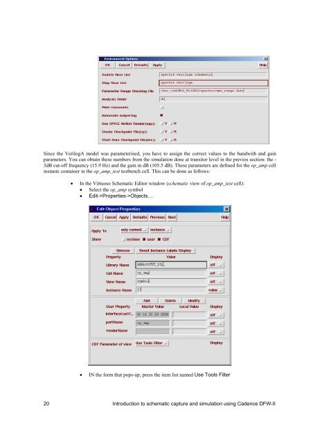
Since the VerilogA model was parameterised, you have <strong>to</strong> assign the correct values <strong>to</strong> the bandwith and gainparameters. You can obtain these numbers from the simulation done at transi<strong>to</strong>r level in the previos section: the -3dB cut-off frequency (15.9 Hz) and the gain in dB (105.5 dB). These parameters are defined for the op_amp cellinstante container in the op_amp_test testbench cell. This can be done as follows:In the Virtuoso Schematic Edi<strong>to</strong>r window (schematic view of op_amp_test cell): Select the op_amp symbol Edit->Properties->Objects…IN the form that pops-up, press the item list named Use Tools Filter20 <strong>Introduction</strong> <strong>to</strong> schematic capture and simulation using <strong>Cadence</strong> DFW-II