Onix Installation Manual.qxd - Affordable Home Inspections
Onix Installation Manual.qxd - Affordable Home Inspections
Onix Installation Manual.qxd - Affordable Home Inspections
- No tags were found...

Create successful ePaper yourself
Turn your PDF publications into a flip-book with our unique Google optimized e-Paper software.
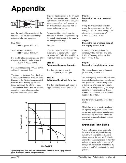
Appendixtates the required flow rate (gpm) forthe zone. This can be calculated byusing the following equation:Pure Water:BTU = gpm × 500 × ∆TThe zone head pressure is the pressuredrop seen through the <strong>Onix</strong> circuits ina given zone. It is calculated using thepressure drop charts and is added tothe pressure drop associated with thesupply and return piping.Because the <strong>Onix</strong> circuits are alwaysplumbed in parallel, the pressure dropfor an individual circuit is the same asthe zone pressure drop.Example:Step 3:Determine the zone pressuredropUsing the pressure drop chart forwater, the pressure drop per foot oftubing is 0.031 ft.-hd./ft. tubing. Thisgives a zone pressure drop of0.031 × 200 = 6.20 ft.-hd.Step 4:Determine the pressure drop ofthe supply/return lines.50% Glycol-50% Water:BTU = gpm × 455 × ∆TFor most heating systems using a 20¡Ftemperature drop it can be assumed1 gpm = 10,000 BTU/hSo, a system requiring 100,000 BTU/hwill need 10 gpm of flow.The other performance factor in sizinga circulator is the head pressure. HeadPressure is the friction loss associatedwith the water moving against theinside surface of the tubing or pipe.The circulator should be sized to overcomethis loss, while moving therequired volume of system fluid.10Zone A calls for 20,000 BTU/h tobe delivered to a zone with 5’—200’circuits of 3/8" <strong>Onix</strong>. The manifold islocated 20’ from the mechanical room.Step 1:Determine the zone flow rate.The flow rate for the zone is20,000/10,000 = 2 gpm.Step 2:Determine the circuit flow rate.The flow rate through each circuit is2 gpm/5 circuits = 0.40 gpm/circuitAssuming 3/4" supply lines areinstalled, with a flow rate of 2 gpm.0.02 × 40’ (supply and return distance)= 0.80 ft.-hd.Step 5:Determine complete pump spec.The required pump load is 2 gpm at(6.20 + 0.80) or 7.0 ft.-hd.The actual pump required for this zoneis selected using the given manufacturers guidelines. This is usually donewith the use of a pump curve chart.The chart is set up showing the pumpscapacity at various pressure drops.Choose the pump that best reflects theneeds of the system.For this example, pump 2 is the bestchoice.page 70Head Pressure (ft-hd)86421232 4 6 8 10Flow Rate (GPM)Typical pump sizing chart. Make sure zone circulators are sized to include supply and returnpiping in addition to the zone piping requirements.This information is readily availableon a pump sizing chart. These chartsare created by the pump manufacturerfor each pump model and should beconsulted before selection of a pumpcan be made.Expansion Tank SizingWater will expand as its temperatureincreases. Since a hydronic heatingsystem with an expansion tank is aclosed system, the internal fluid volumeis fixed. A simple ratio of how thevolume, pressure and temperature ofthe system interact can be modeled byusing a simplified version of the idealgas law.Watts Radiant: <strong>Onix</strong> <strong>Installation</strong> <strong>Manual</strong>