Single-Chip Low Cost Low Power RF-Transceiver (Rev. B
Single-Chip Low Cost Low Power RF-Transceiver (Rev. B
Single-Chip Low Cost Low Power RF-Transceiver (Rev. B
- No tags were found...

You also want an ePaper? Increase the reach of your titles
YUMPU automatically turns print PDFs into web optimized ePapers that Google loves.
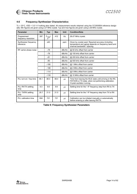
CC25004.6 Frequency Synthesizer CharacteristicsTc = 25°C, VDD = 3.0 V if nothing else stated. All measurement results obtained using the CC2500EM reference design([4]). Min figures are given using a 27 MHz crystal. Typ and max figures are given using a 26 MHz crystal.Parameter Min Typ Max Unit Condition/NoteProgrammedfrequency resolutionSynthesizer frequencytolerance<strong>RF</strong> carrier phase noise397 F XOSC /2 16 412 Hz 26-27 MHz crystal.±40 ppm Given by crystal used. Required accuracy (includingtemperature and aging) depends on frequency band andchannel bandwidth / spacing.–78 dBc/Hz @ 50 kHz offset from carrier–78 dBc/Hz @ 100 kHz offset from carrier–81 dBc/Hz @ 200 kHz offset from carrier–90 dBc/Hz @ 500 kHz offset from carrier–100 dBc/Hz @ 1 MHz offset from carrier–108 dBc/Hz @ 2 MHz offset from carrier–114 dBc/Hz @ 5 MHz offset from carrier–118 dBc/Hz @ 10 MHz offset from carrierPLL turn-on / hop time 85.1 88.4 88.4 µs Time from leaving the IDLE state until arriving in the RX,FSTXON or TX state, when not performing calibration.Crystal oscillator running.PLL RX/TX settlingtimePLL TX/RX settlingtime9.3 9.6 9.6 µs Settling time for the 1·IF frequency step from RX to TX20.7 21.5 21.5 µs Settling time for the 1·IF frequency step from TX to RXPLL calibration time 694 721 721 µs Calibration can be initiated manually or automaticallybefore entering or after leaving RX/TX.Table 9: Frequency Synthesizer ParametersSWRS040B Page 14 of 92