Single-Chip Low Cost Low Power RF-Transceiver (Rev. B
Single-Chip Low Cost Low Power RF-Transceiver (Rev. B
Single-Chip Low Cost Low Power RF-Transceiver (Rev. B
- No tags were found...

You also want an ePaper? Increase the reach of your titles
YUMPU automatically turns print PDFs into web optimized ePapers that Google loves.
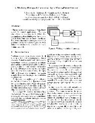
CC250031.6 Crystal Drift CompensationThe CC2500 has a very fine frequencyresolution (see Table 9). This feature can beused to compensate for frequency offset anddrift.The frequency offset between an ‘external’transmitter and the receiver is measured in theCC2500 and can be read back from theFREQEST status register as described inSection 14.1. The measured frequency offsetcan be used to calibrate the frequency usingthe ‘external’ transmitter as the reference. Thatis, the received signal of the device will matchthe receiver’s channel filter better. In the sameway the centre frequency of the transmittedsignal will match the ‘external’ transmitter’ssignal.31.7 Spectrum Efficient ModulationCC2500 also has the possibility to useGaussian shaped 2-FSK (GFSK). Thisspectrum-shaping feature improves adjacentchannel power (ACP) and occupiedbandwidth. In ‘true’ 2-FSK systems with abruptfrequency shifting, the spectrum is inherentlybroad. By making the frequency shift ‘softer’,the spectrum can be made significantlynarrower. Thus, higher data rates can betransmitted in the same bandwidth usingGFSK.31.8 <strong>Low</strong> <strong>Cost</strong> SystemsA differential antenna will eliminate the needfor a balun, and the DC biasing can beachieved in the antenna topology, see Figure3. The CC25XX Folded Dipole referencedesign [8] contains schematics and layout filesfor a CC2500EM with a folded dipole PCBantenna. Please see DN004 [9] for moredetails on this design.A HC-49 type SMD crystal is used in theCC2500EM reference design [4]. Note that thecrystal package strongly influences the price.In a size constrained PCB design a smaller,but more expensive, crystal may be used.31.9 Battery Operated SystemsIn low power applications, the SLEEP statewith the crystal oscillator core switched offshould be used when the CC2500 is not active.It is possible to leave the crystal oscillator corerunning in the SLEEP state if start-up time iscritical.The WOR functionality should be used in lowpower applications.31.10 Increasing Output <strong>Power</strong>In some applications it may be necessary toextend the link range. Adding an externalpower amplifier is the most effective way ofdoing this.The power amplifier should be insertedbetween the antenna and the balun, and twoT/R switches are needed to disconnect the PAin RX mode. See Figure 29.AntennaFilterPABalunCC2500T/R switchT/R switchFigure 29. Block Diagram of CC2500 Usage with External <strong>Power</strong> AmplifierSWRS040B Page 57 of 92