Single-Chip Low Cost Low Power RF-Transceiver (Rev. B
Single-Chip Low Cost Low Power RF-Transceiver (Rev. B
Single-Chip Low Cost Low Power RF-Transceiver (Rev. B
- No tags were found...

You also want an ePaper? Increase the reach of your titles
YUMPU automatically turns print PDFs into web optimized ePapers that Google loves.
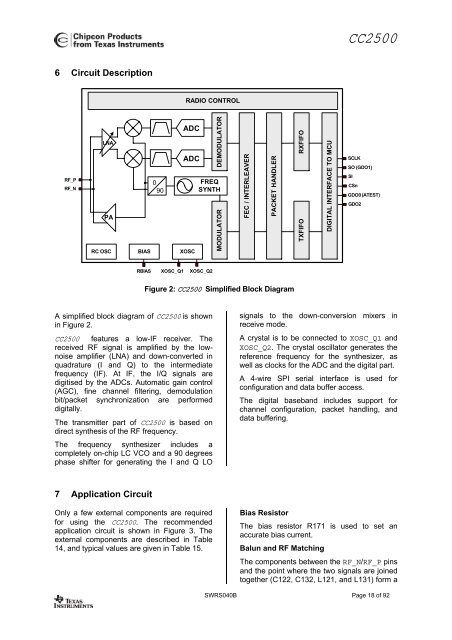
CC25006 Circuit DescriptionRADIO CONTROL<strong>RF</strong>_P<strong>RF</strong>_NLNAPARC OSCBIAS090ADCADCXOSCDEMODULATO<strong>RF</strong>REQSYNTHMODULATO<strong>RF</strong>EC / INTERLEAVERPACKET HANDLERRXFIFOTXFIFODIGITAL INTE<strong>RF</strong>ACE TO MCUSCLKSO (GDO1)SICSnGDO0 (ATEST)GDO2RBIAS XOSC_Q1 XOSC_Q2Figure 2: CC2500 Simplified Block DiagramA simplified block diagram of CC2500 is shownin Figure 2.CC2500 features a low-IF receiver. Thereceived <strong>RF</strong> signal is amplified by the lownoiseamplifier (LNA) and down-converted inquadrature (I and Q) to the intermediatefrequency (IF). At IF, the I/Q signals aredigitised by the ADCs. Automatic gain control(AGC), fine channel filtering, demodulationbit/packet synchronization are performeddigitally.The transmitter part of CC2500 is based ondirect synthesis of the <strong>RF</strong> frequency.The frequency synthesizer includes acompletely on-chip LC VCO and a 90 degreesphase shifter for generating the I and Q LOsignals to the down-conversion mixers inreceive mode.A crystal is to be connected to XOSC_Q1 andXOSC_Q2. The crystal oscillator generates thereference frequency for the synthesizer, aswell as clocks for the ADC and the digital part.A 4-wire SPI serial interface is used forconfiguration and data buffer access.The digital baseband includes support forchannel configuration, packet handling, anddata buffering.7 Application CircuitOnly a few external components are requiredfor using the CC2500. The recommendedapplication circuit is shown in Figure 3. Theexternal components are described in Table14, and typical values are given in Table 15.Bias ResistorThe bias resistor R171 is used to set anaccurate bias current.Balun and <strong>RF</strong> MatchingThe components between the <strong>RF</strong>_N/<strong>RF</strong>_P pinsand the point where the two signals are joinedtogether (C122, C132, L121, and L131) form aSWRS040B Page 18 of 92