Single-Chip Low Cost Low Power RF-Transceiver (Rev. B
Single-Chip Low Cost Low Power RF-Transceiver (Rev. B
Single-Chip Low Cost Low Power RF-Transceiver (Rev. B
- No tags were found...

Create successful ePaper yourself
Turn your PDF publications into a flip-book with our unique Google optimized e-Paper software.
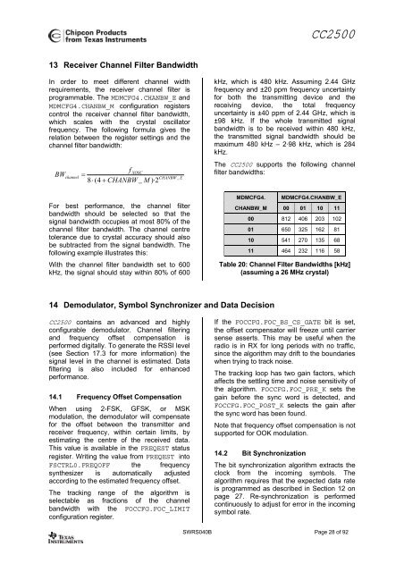
CC250013 Receiver Channel Filter BandwidthIn order to meet different channel widthrequirements, the receiver channel filter isprogrammable. The MDMCFG4.CHANBW_E andMDMCFG4.CHANBW_M configuration registerscontrol the receiver channel filter bandwidth,which scales with the crystal oscillatorfrequency. The following formula gives therelation between the register settings and thechannel filter bandwidth:BWchannelfXOSC=8 ⋅ (4 + CHANBW_M )·2CHANBW_EFor best performance, the channel filterbandwidth should be selected so that thesignal bandwidth occupies at most 80% of thechannel filter bandwidth. The channel centretolerance due to crystal accuracy should alsobe subtracted from the signal bandwidth. Thefollowing example illustrates this:With the channel filter bandwidth set to 600kHz, the signal should stay within 80% of 600kHz, which is 480 kHz. Assuming 2.44 GHzfrequency and ±20 ppm frequency uncertaintyfor both the transmitting device and thereceiving device, the total frequencyuncertainty is ±40 ppm of 2.44 GHz, which is±98 kHz. If the whole transmitted signalbandwidth is to be received within 480 kHz,the transmitted signal bandwidth should bemaximum 480 kHz – 2·98 kHz, which is 284kHz.The CC2500 supports the following channelfilter bandwidths:MDMCFG4.MDMCFG4.CHANBW_ECHANBW_M 00 01 10 1100 812 406 203 10201 650 325 162 8110 541 270 135 6811 464 232 116 58Table 20: Channel Filter Bandwidths [kHz](assuming a 26 MHz crystal)14 Demodulator, Symbol Synchronizer and Data DecisionCC2500 contains an advanced and highlyconfigurable demodulator. Channel filteringand frequency offset compensation isperformed digitally. To generate the RSSI level(see Section 17.3 for more information) thesignal level in the channel is estimated. Datafiltering is also included for enhancedperformance.14.1 Frequency Offset CompensationWhen using 2-FSK, GFSK, or MSKmodulation, the demodulator will compensatefor the offset between the transmitter andreceiver frequency, within certain limits, byestimating the centre of the received data.This value is available in the FREQEST statusregister. Writing the value from FREQEST intoFSCTRL0.FREQOFF the frequencysynthesizer is automatically adjustedaccording to the estimated frequency offset.The tracking range of the algorithm isselectable as fractions of the channelbandwidth with the FOCCFG.FOC_LIMITconfiguration register.If the FOCCFG.FOC_BS_CS_GATE bit is set,the offset compensator will freeze until carriersense asserts. This may be useful when theradio is in RX for long periods with no traffic,since the algorithm may drift to the boundarieswhen trying to track noise.The tracking loop has two gain factors, whichaffects the settling time and noise sensitivity ofthe algorithm. FOCCFG.FOC_PRE_K sets thegain before the sync word is detected, andFOCCFG.FOC_POST_K selects the gain afterthe sync word has been found.Note that frequency offset compensation is notsupported for OOK modulation.14.2 Bit SynchronizationThe bit synchronization algorithm extracts theclock from the incoming symbols. Thealgorithm requires that the expected data rateis programmed as described in Section 12 onpage 27. Re-synchronization is performedcontinuously to adjust for error in the incomingsymbol rate.SWRS040B Page 28 of 92