- Page 1 and 2:
Rotary Seal DesignGuideCatalog EPS
- Page 3 and 4:
Rotary SealDesign GuideTable of Con
- Page 5 and 6:
IntroductionCatalog EPS 5350/USA11T
- Page 7 and 8:
Seal Decision TreeOil Retention, Sh
- Page 9 and 10:
Clipper Oil Seal and Parker Oil Sea
- Page 11 and 12:
Catalog EPS 5350/USAIntroduction1En
- Page 13 and 14:
Sealing SystemsThe completeness of
- Page 15 and 16:
EngineeringContentsRotary Shaft Sea
- Page 17 and 18:
Catalog EPS 5350/USAEngineeringHow
- Page 19 and 20:
Catalog EPS 5350/USAEngineeringThis
- Page 21 and 22:
Catalog EPS 5350/USAEngineeringWhen
- Page 23 and 24:
Catalog EPS 5350/USAEngineeringOthe
- Page 25 and 26:
Catalog EPS 5350/USAEngineeringHous
- Page 27 and 28:
Catalog EPS 5350/USAEngineering5. V
- Page 29 and 30:
Catalog EPS 5350/USAEngineeringPTFE
- Page 31 and 32:
Catalog EPS 5350/USAEngineeringCant
- Page 33 and 34:
Catalog EPS 5350/USAEngineeringCata
- Page 35 and 36:
Catalog EPS 5350/USAEngineeringShaf
- Page 37 and 38:
Catalog EPS 5350/USAEngineeringFlex
- Page 39 and 40:
Catalog EPS 5350/USAEngineeringShaf
- Page 41 and 42:
Catalog EPS 5350/USAEngineeringBear
- Page 43 and 44:
Catalog EPS 5350/USAEngineeringExce
- Page 45 and 46:
MaterialsMaterials ExcellenceParker
- Page 47 and 48:
Catalog EPS 5350/USAMaterialsCatalo
- Page 49 and 50:
Product OfferingCatalog EPS 5350/US
- Page 51 and 52:
Catalog EPS 5350/USAProduct Offerin
- Page 53 and 54:
Catalog EPS 5350/USAProduct Offerin
- Page 55 and 56:
Catalog EPS 5350/USAProduct Offerin
- Page 57 and 58:
Catalog EPS 5350/USAProduct Offerin
- Page 59 and 60:
Catalog EPS 5350/USAProduct Offerin
- Page 61 and 62:
Catalog EPS 5350/USAProduct Offerin
- Page 63 and 64:
Catalog EPS 5350/USAProduct Offerin
- Page 65 and 66:
Catalog EPS 5350/USAProduct Offerin
- Page 67 and 68:
Catalog EPS 5350/USAProduct Offerin
- Page 69 and 70:
Catalog EPS 5350/USAProduct Offerin
- Page 71 and 72:
Catalog EPS 5350/USAProduct Offerin
- Page 73 and 74:
Clipper ® Oil SealsIntroductionCon
- Page 75 and 76:
Clipper ® Oil SealsEngineeringShaf
- Page 77 and 78:
Clipper ® Oil SealsCatalog EPS 535
- Page 79 and 80:
Clipper ® Oil SealsCatalog EPS 535
- Page 81 and 82:
Clipper ® Oil SealsProduct Offerin
- Page 83 and 84:
Clipper ® Oil SealsCatalog EPS 535
- Page 85 and 86:
Clipper ® Oil SealsCatalog EPS 535
- Page 87 and 88:
Clipper ® Oil SealsLUPW, LPDW, LDS
- Page 89 and 90:
Clipper ® Oil SealsOL ProfileCatal
- Page 91 and 92:
Clipper ® Oil SealsTSS ProfileCata
- Page 93 and 94:
Clipper ® Oil SealsRPDT ProfileCat
- Page 95 and 96:
Clipper ® Oil SealsSS, SDS Profile
- Page 97 and 98:
Clipper ® Oil SealsTMAL, TMAS Prof
- Page 99 and 100:
Clipper ® Oil SealsRUP, RPD Profil
- Page 101 and 102:
Clipper ® Oil SealsCatalog EPS 535
- Page 103 and 104:
Parker Oil SealsIntroductionContent
- Page 105 and 106:
Parker Oil SealsCatalog EPS 5350/US
- Page 107 and 108:
Parker Oil SealsMaterialsCommon Mat
- Page 109 and 110:
Parker Oil SealsCatalog EPS 5350/US
- Page 111 and 112:
Parker Oil SealsProduct OfferingPar
- Page 113 and 114:
Parker Oil SealsCatalog EPS 5350/US
- Page 115 and 116:
Parker Oil SealsSpringless Grease R
- Page 117 and 118:
Parker Oil SealsMedium Pressure Pro
- Page 119 and 120:
Parker Oil SealsHigh Eccentricity S
- Page 121 and 122: Parker Oil SealsPTFE/Elastomer Prof
- Page 123 and 124: Shaft SleevesIntroductionContentsEn
- Page 125 and 126: Shaft SleevesMaterialsCommon Materi
- Page 127 and 128: ProTech Bearing IsolatorsIntroduct
- Page 129 and 130: ProTech Bearing IsolatorsCatalog EP
- Page 131 and 132: ProTech Bearing IsolatorsEngineeri
- Page 133 and 134: ProTech Bearing IsolatorsCatalog EP
- Page 135 and 136: ProTech Bearing IsolatorsCatalog EP
- Page 137 and 138: ProTech Bearing IsolatorsCatalog EP
- Page 139 and 140: ProTech Bearing IsolatorsCatalog EP
- Page 141 and 142: ProTech Bearing IsolatorsCatalog EP
- Page 143 and 144: ProTech Bearing IsolatorsCatalog EP
- Page 145 and 146: ProTech Bearing IsolatorsCatalog EP
- Page 147 and 148: ProTech Bearing IsolatorsCatalog EP
- Page 149 and 150: ProTech Bearing IsolatorsLN Profil
- Page 151 and 152: ProTech Bearing IsolatorsLW Profil
- Page 153 and 154: ProTech Bearing IsolatorsSL Profil
- Page 155 and 156: ProTech Bearing IsolatorsML Profil
- Page 157 and 158: ProTech Bearing IsolatorsFS-360 Pr
- Page 159 and 160: FlexiLip IntroductionContentsEngine
- Page 161 and 162: FlexiLip EngineeringCatalog EPS 535
- Page 163 and 164: FlexiLipCatalog EPS 5350/USAEnginee
- Page 165 and 166: FlexiLipCatalog EPS 5350/USAMateria
- Page 167 and 168: FlexiLip Product OfferingThe key ap
- Page 169 and 170: FlexiLipCatalog EPS 5350/USAProduct
- Page 171: FlexiCase IntroductionContentsEngin
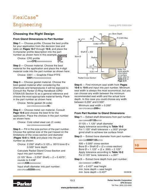
- Page 175 and 176: FlexiCaseCatalog EPS 5350/USAEngine
- Page 177 and 178: FlexiCase Product OfferingCatalog E
- Page 179 and 180: FlexiCaseCatalog EPS 5350/USAProduc
- Page 181 and 182: FlexiSeal ® RotaryIntroductionCont
- Page 183 and 184: FlexiSeal ® RotaryCatalog EPS 5350
- Page 185 and 186: FlexiSeal ® RotaryProduct Offering
- Page 187 and 188: FlexiSeal ® RotaryCatalog EPS 5350
- Page 189 and 190: FlexiSeal ® RotaryFC and FH Profil
- Page 191 and 192: FlexiSeal ® RotaryFF Profiles —
- Page 193 and 194: V-Seals and ExcludersIntroductionCa
- Page 195 and 196: V-Seals and ExcludersMaterialsCatal
- Page 197 and 198: V-Seals and ExcludersA ProfileCatal
- Page 199 and 200: V-Seals and ExcludersL ProfileCatal
- Page 201 and 202: V-Seals and ExcludersDS and SSW Pro
- Page 203: Rotary SealDesign GuideAppendixDesi
- Page 206 and 207: ACatalog EPS 5350/USADesign Action
- Page 208 and 209: AACatalog EPS 5350/USANotesA-4 Park
- Page 210 and 211: Catalog EPS 5350/USARotary Lip Seal
- Page 212 and 213: Catalog EPS 5350/USARotary Lip Seal
- Page 214 and 215: Catalog EPS 5350/USARotary Lip Seal
- Page 216 and 217: Catalog EPS 5350/USARotary Lip Seal
- Page 218 and 219: Catalog EPS 5350/USARotary Lip Seal
- Page 220 and 221: Catalog EPS 5350/USARotary Lip Seal
- Page 222 and 223:
Catalog EPS 5350/USARotary Lip Seal
- Page 224 and 225:
Catalog EPS 5350/USARotary Lip Seal
- Page 226 and 227:
Catalog EPS 5350/USARotary Lip Seal
- Page 228 and 229:
Catalog EPS 5350/USARotary Lip Seal
- Page 230 and 231:
Catalog EPS 5350/USARotary Lip Seal
- Page 232 and 233:
Catalog EPS 5350/USARotary Lip Seal
- Page 234 and 235:
Catalog EPS 5350/USARotary Lip Seal
- Page 236 and 237:
Catalog EPS 5350/USARotary Lip Seal
- Page 238 and 239:
Catalog EPS 5350/USARotary Lip Seal
- Page 240 and 241:
Catalog EPS 5350/USARotary Lip Seal
- Page 242 and 243:
Catalog EPS 5350/USARotary Lip Seal
- Page 244 and 245:
Catalog EPS 5350/USARotary Lip Seal
- Page 246 and 247:
Catalog EPS 5350/USARotary Lip Seal
- Page 248 and 249:
Catalog EPS 5350/USARotary Lip Seal
- Page 250 and 251:
Catalog EPS 5350/USARotary Lip Seal
- Page 252 and 253:
Catalog EPS 5350/USARotary Lip Seal
- Page 254 and 255:
Catalog EPS 5350/USARotary Lip Seal
- Page 256 and 257:
Catalog EPS 5350/USARotary Lip Seal
- Page 258 and 259:
Catalog EPS 5350/USARotary Lip Seal
- Page 260 and 261:
Catalog EPS 5350/USARotary Lip Seal
- Page 262 and 263:
Catalog EPS 5350/USARotary Lip Seal
- Page 264 and 265:
Catalog EPS 5350/USARotary Lip Seal
- Page 266 and 267:
Catalog EPS 5350/USARotary Lip Seal
- Page 268 and 269:
Catalog EPS 5350/USARotary Lip Seal
- Page 270 and 271:
Catalog EPS 5350/USARotary Lip Seal
- Page 272 and 273:
Catalog EPS 5350/USARotary Lip Seal
- Page 274 and 275:
Catalog EPS 5350/USARotary Lip Seal
- Page 276 and 277:
Catalog EPS 5350/USARotary Lip Seal
- Page 278 and 279:
Catalog EPS 5350/USARotary Lip Seal
- Page 280 and 281:
Catalog EPS 5350/USARotary Lip Seal
- Page 282 and 283:
Catalog EPS 5350/USARotary Lip Seal
- Page 284 and 285:
Catalog EPS 5350/USARotary Lip Seal
- Page 286 and 287:
Catalog EPS 5350/USARotary Lip Seal
- Page 288 and 289:
Catalog EPS 5350/USARotary Lip Seal
- Page 290 and 291:
Catalog EPS 5350/USARotary Lip Seal
- Page 292 and 293:
Catalog EPS 5350/USARotary Lip Seal
- Page 294 and 295:
BBHigh Misalignment Inch1.000 to 3.
- Page 296 and 297:
Catalog EPS 5350/USAHigh Misalignme
- Page 298 and 299:
Catalog EPS 5350/USAHigh Misalignme
- Page 300 and 301:
Catalog EPS 5350/USAHigh Misalignme
- Page 302 and 303:
Catalog EPS 5350/USAFlexiSeal ® In
- Page 304 and 305:
Catalog EPS 5350/USAFlexiSeal ® In
- Page 306 and 307:
Catalog EPS 5350/USAFlexiSeal ® In
- Page 308 and 309:
Catalog EPS 5350/USAFlexiSeal ® In
- Page 310 and 311:
Catalog EPS 5350/USARotary Lip Seal
- Page 312 and 313:
Catalog EPS 5350/USARotary Lip Seal
- Page 314 and 315:
Catalog EPS 5350/USARotary Lip Seal
- Page 316 and 317:
Catalog EPS 5350/USARotary Lip Seal
- Page 318 and 319:
Catalog EPS 5350/USARotary Lip Seal
- Page 320 and 321:
Catalog EPS 5350/USARotary Lip Seal
- Page 322 and 323:
Catalog EPS 5350/USARotary Lip Seal
- Page 324 and 325:
Catalog EPS 5350/USARotary Lip Seal
- Page 326 and 327:
Catalog EPS 5350/USARotary Lip Seal
- Page 328 and 329:
Catalog EPS 5350/USARotary Lip Seal
- Page 330 and 331:
FlexiSeal ® MetricCatalog EPS 5350
- Page 332 and 333:
Catalog EPS 5350/USASolid to Split
- Page 334 and 335:
Catalog EPS 5350/USASolid to Split
- Page 336 and 337:
Catalog EPS 5350/USASolid to Split
- Page 338 and 339:
Catalog EPS 5350/USASleeve & V-Seal
- Page 340 and 341:
Catalog EPS 5350/USASleeve & V-Seal
- Page 342 and 343:
Catalog EPS 5350/USASleeve & V-Seal
- Page 344 and 345:
Catalog EPS 5350/USASleeve & V-Seal
- Page 346 and 347:
Catalog EPS 5350/USASleeve & V-Seal
- Page 348 and 349:
Catalog EPS 5350/USASleeve & V-Seal
- Page 350 and 351:
Catalog EPS 5350/USASleeve & V-Seal
- Page 352 and 353:
Catalog EPS 5350/USASleeve & V-Seal
- Page 354 and 355:
Catalog EPS 5350/USASleeve & V-Seal
- Page 356 and 357:
Catalog EPS 5350/USASleeve & V-Seal
- Page 358 and 359:
Catalog EPS 5350/USASleeve & V-Seal
- Page 360 and 361:
Catalog EPS 5350/USAProTech Sizes
- Page 362 and 363:
Catalog EPS 5350/USAProTech Sizes
- Page 364 and 365:
Catalog EPS 5350/USAProTech Sizes
- Page 366 and 367:
Catalog EPS 5350/USAProTech Sizes
- Page 368 and 369:
Catalog EPS 5350/USAProTech Sizes
- Page 370 and 371:
Catalog EPS 5350/USAProTech Sizes
- Page 372 and 373:
Catalog EPS 5350/USAProTech Sizes
- Page 374 and 375:
Catalog EPS 5350/USAProTech Sizes
- Page 376 and 377:
Catalog EPS 5350/USAProTech Sizes
- Page 378 and 379:
Catalog EPS 5350/USAProTech Sizes
- Page 380 and 381:
Catalog EPS 5350/USAProTech Sizes
- Page 382 and 383:
Catalog EPS 5350/USAProTech Sizes
- Page 384 and 385:
Catalog EPS 5350/USAProTech Sizes
- Page 386 and 387:
Catalog EPS 5350/USAProTech Sizes
- Page 388 and 389:
Catalog EPS 5350/USAProTech Sizes
- Page 390 and 391:
Catalog EPS 5350/USAProTech Sizes
- Page 392 and 393:
Catalog EPS 5350/USAProTech Sizes
- Page 394 and 395:
ProTech Sizes Metric12.7 to 30.0Ca
- Page 396 and 397:
Catalog EPS 5350/USAProTech Sizes
- Page 398 and 399:
Catalog EPS 5350/USAProTech Sizes
- Page 400 and 401:
Catalog EPS 5350/USAProTech Sizes
- Page 402 and 403:
RPM to FPM ConversionCatalog EPS 53
- Page 404 and 405:
Pressure ConversionPSI / BARCatalog
- Page 406 and 407:
Catalog EPS 5350/USAChemical Compat
- Page 408 and 409:
Catalog EPS 5350/USAChemical Compat
- Page 410 and 411:
Catalog EPS 5350/USAChemical Compat
- Page 412 and 413:
Catalog EPS 5350/USAChemical Compat
- Page 414 and 415:
Catalog EPS 5350/USAChemical Compat
- Page 416 and 417:
Catalog EPS 5350/USAChemical Compat
- Page 418 and 419:
Catalog EPS 5350/USAChemical Compat
- Page 420 and 421:
Catalog EPS 5350/USAChemical Compat
- Page 422 and 423:
Catalog EPS 5350/USANotesHHH-18 Par
- Page 424 and 425:
Catalog EPS 5350/USAOld to New Part
- Page 426 and 427:
Catalog EPS 5350/USAOld to New Part
- Page 428 and 429:
Catalog EPS 5350/USANotesIII-6 Park
- Page 430 and 431:
Catalog EPS 5350/USAOther Parker EP
- Page 432 and 433:
About Parker Hannifin CorporationCa
- Page 434:
Parker Hannifin Corporation, Seal G


