

"Linear Equation Solver using CMOS Technology" - Microelectronic ...
"Linear Equation Solver using CMOS Technology" - Microelectronic ...
"Linear Equation Solver using CMOS Technology" - Microelectronic ...

Create successful ePaper yourself
Turn your PDF publications into a flip-book with our unique Google optimized e-Paper software.
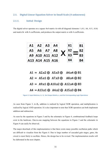
2.1. Digital <strong>Linear</strong> <strong>Equation</strong> <strong>Solver</strong> in Small Scale (4 unknowns)2.1.1. Initial DesignThe digital solver operates on a square 4x4 matrix A with all diagonal elements 1 (A1, A6, A11, A16)and matrix b with 4 coefficients, and produces the output matrix x with 4 coefficients.A1 = A2.x2 ⊕ A3.x3 ⊕A2 = A5.x1 ⊕ A7.x3 ⊕A4.x4 ⊕ B1A8.x4 ⊕ B2A3 = A9.x1 ⊕ A10.x2 ⊕ A12.x4 ⊕ B3A4 = A13.x1 ⊕ A4.x2 ⊕ A15.x3 ⊕ B4Figure 3. Input Matrices, A, B, the Output Matrix, x, and the Corresponding Logic OperationsAs seen from Figure 3, in Z 2 , addition is realized by logical XOR operation, and multiplication isrealized by logical AND operation. It is also important to note that XOR operation can both implementaddition and subtraction.As seen by the equations in Figure 3 and by the schematic in Figure 4, combinational feedback loopsexist in the hardware. One-to-one mapping between the equations in Figure 3 and the schematic inFigure 4 can easily be observed.The major drawback of this implementation is that there exists many possible oscillation paths whichare difficult to visualize from the Figure 4. Due to large number of cascaded gain stages, gates, thecircuit is most likely to oscillate. Hence, the design has to be revised. The implementation results willbe elaborated in the next chapter.11


