

"Linear Equation Solver using CMOS Technology" - Microelectronic ...
"Linear Equation Solver using CMOS Technology" - Microelectronic ...
"Linear Equation Solver using CMOS Technology" - Microelectronic ...

Create successful ePaper yourself
Turn your PDF publications into a flip-book with our unique Google optimized e-Paper software.
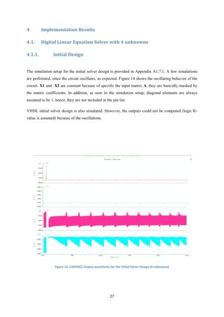
4 Implementation Results4.1. Digital <strong>Linear</strong> <strong>Equation</strong> <strong>Solver</strong> with 4 unknowns4.1.1. Initial DesignThe simulation setup for the initial solver design is provided in Appendix A1.7.1. A few simulationsare performed, since the circuit oscillates, as expected. Figure 14 shows the oscillating behavior of thecircuit. X1 and X2 are constant because of specific the input matrix A, they are basically masked bythe matrix coefficients. In addition, as seen in the simulation setup, diagonal elements are alwaysassumed to be 1, hence, they are not included in the pin list.VHDL initial solver design is also simulated. However, the outputs could not be computed (logic U-value is assumed) because of the oscillations.Figure 14. CADENCE Output waveforms for the Initial <strong>Solver</strong> Design (4 unknowns)27


