Page 4 of 14TOTALPAC2TOTALPAC2 Integrated Fire Protection SystemMechanical Section - <strong>Dry</strong> Pipe SystemImportant Settings HP ® <strong>Dry</strong> Pipe System:.1 Provide a minimum or maximum pneumatic air pressure toAnti-Flood Device as shown in Table 1 above for systemwater pressures up to 250 psi (17,2 BAR) maximum..a Set air pressure supervisory switch (E3) to activate at5 psi less than the set pneumatic supervisory airpressure on pressure drop, as shown in Table 1..b Air supervisory switch (E3) should be wired to activatean alarm to signal a "low air" pressure condition.Activation of an alarm to signal a high pressurecondition may be installed. Refer to the applicableinstallation standards and Authority HavingJurisdiction..2 Alarm pressure switch (C1) should activate whenpressurized to 4 to 8 psi (27 to 55 kPa) on pressure rise.Alarm pressure switch (C1) should be wired to activate thewater flow alarm.1.4 System Operation1.4.1 In the SET condition: Regular <strong>Dry</strong> Pipe system: In the normal set condition thesystem piping is filled with compressed air or nitrogen. Theclapper (E) and air plate (L) assemblies (see Figure 2)combine to form a floating member assembly. With theclapper assembly (E) latched closed, system air pressureforces the member assembly down, sealing the water seat (R)from the intermediate chamber. HP ® <strong>Dry</strong> Pipe System: System water supply pressureenters the priming chamber of the <strong>Dry</strong> Valve (A1) through the¼" (8 mm) priming line which includes a normally open primingvalve (B1), strainer (B2), restricted orifice (B3) and check valve(B4. In the SET position, the water supply pressure is trappedin the priming chamber by check valve (B4) and Anti-flooddevice.Anti-flood device is held closed by pressure maintained on thesystem riser. Air pressure is isolated from the Deluge outlet on3" systems and above by a Viking Easy-Riser soft seat checkvalve (D2). The pressure in the priming chamber holds theDeluge Valve (A1) clapper closed, keeping the outlet chamberand system piping dry.1.4.2 In a fire condition: Regular <strong>Dry</strong> Pipe system: When a sprinkler operates, thesystem air pressure is reduced. When system air pressure isreduced to the differential pressure tripping point of the valve,water supply pressure in the inlet chamber lifts the memberassembly off the water seat (R) and flows into the intermediatechamber.As the member assembly continues to rise, the latchinghook (Q) is forced against operating pin (Y) which causesthe hook (Q) to pivot on hook rod (F2) and unlatch theclapper.The clapper is spring-loaded and swings to a full-openlocked position (see figure 2A). When equipped with theoptional Accelerator and external Anti-flood Device, a dropin system air pressure causes the Accelerator to operate.Operation of the Accelerator causes the Anti-floodDevice to open allowing system air pressure to enter thedry valve intermediate chamber. This immediately destroysthe pressure differential, causing the member assembly torise faster.The intermediate chamber is normally at atmosphericpressure and is connected to the alarm line. When thevalve trips the intermediate chamber and alarm line arepressurized with the system water pressure, activatingalarms connected to the <strong>Dry</strong> Valve trim.Sprinkling continues until the main supply water controlvalve (D1) is manually closed. HP ® <strong>Dry</strong> Pipe System: When a Viking sprinkler headoperates, pressure in the system piping escapes causingalarms controlled by Air Supervisory Switch (E4) to activateand Anti-flood Device to open. When Anti-flood Deviceopens, pressure is released from the priming chamber toopen drain manifold faster than it is supplied through therestricted orifice (B3). The Deluge valve (A1) clapperopens to allow water to flow into the system piping andactivate alarm devices, including a water flow AlarmPressure Switch (C1). Water will immediately flow from anysprinklers which may have operated. When the deluge valveoperates, the sensing end of the PORV (B9) is pressurized,causing the PORV to open. When the PORV opens, it drains thepriming water pressure of the priming chamber, preventing theDeluge Valve (A1) from resetting, even if the open releasingdevices close. The Deluge Valve can only be reset after thesystem is taken out of service, and the outlet chamber of thedeluge valve and associated trim piping is depressurized anddrained.Downstream of the discharge outlet, a check valve (D2) isinstalled to isolate the discharge outlet from system airpressure. When the water from the discharge outlet passesby the check valve, it will enter to air connection to thesystem riser. To eliminate water from entering the VikingHP dry system trim, a Model A-1 Float Check Valve (F5) isinstalled between the anti-flood device and the systemriser. The Model A-1 Float Check Valve (F5) allows air topass from the system riser to the anti-flood device to set thesystem.When the system discharges, the Model A-1 Float CheckValve (F5) closes when water flows to the inlet side of thedevice, protecting the anti-flood device from water pressureon its inlet end and protecting the Deluge Valve from resetting.FM-086G-0-26C
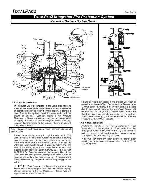
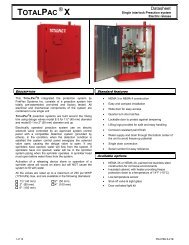
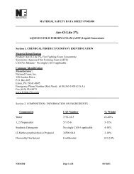
TOTALPAC2 Page 5 of 14TOTALPAC2 Integrated Fire Protection SystemMechanical Section - <strong>Dry</strong> Pipe SystemDOutletACZ2BWQZ1YHEGJF1F2GXKGMLWPVU1.4.2 Trouble conditions:TFigure 2 Regular <strong>Dry</strong> Pipe system: If the valve trips when nosprinkler has fused, either there a loss of air in the system oran extreme pressure surge in the water supply. If there is aloss of air in the system, check for leaks and check forproper air supply. Consider adding a Air PressureMaintenance Device on systems provided with an externalair supply. If there is an extreme surge in the water supply,increase the air pressure on the system. The maximum limitis 60 psi (414 kPa).Note: Increasing system air pressure may increase trip time ofthe dry valve.If water is constantly passing through the drip check (B7)when the valve is in the SET position, either water is leakingover the water seat into the intermediate chamber or thealarm test valve (B5) in the bypass connection of the dryvalve trim is not tightly closed. If water is leaking over theseat of the valve, inspect and clean the water seat andclapper rubber (Refer to section 4. PLACING THE SYSTEMIN SERVICE). Consider replacing the clapper rubber. If thewater seat has been pitted or damaged by debris it may benecessary to replace the base assembly. If the alarm testvalve (B5) is leaking, verify that water is not getting past thevalve. HP ® <strong>Dry</strong> Pipe System: In the event of an air supplyfailure and slow leakage of air from the system piping,alarms connected to the Air Supervisory Switch (E3) willsignal a low air pressure condition.SRNInlet ChamberIntermediateChamberFailure to restore air supply to the system will result inoperation of the Anti-Flood Device and the Deluge valve(A1) will open. Similarly, if the system piping is leakingdue to mechanical damage, the Anti-Flood Device willoperate and the Deluge valve (A1) will open. Water willflow from any open sprinklers or piping on the system.Water motor alarms (C2) and alarms connected to AlarmPressure Switch (C1) will activate.1.4.3 Manual operation:Anytime the handle of the Priming Water Level TestValve (B1) on the regular <strong>Dry</strong> Pipe system or theEmergency Release (B10) on the HP <strong>Dry</strong> pipe system ispulled, pressure is released from the priming chamber;<strong>Dry</strong> Pipe or Deluge Valve (A1) will open.Water will flow from any open sprinklers and/or otheropening in the sprinkler piping and alarm devices (C1 &C2) will operate.FM-086G-0-26C