TotalPac®2 Dry - FIREFLEX SYSTEMS
TotalPac®2 Dry - FIREFLEX SYSTEMS
TotalPac®2 Dry - FIREFLEX SYSTEMS

You also want an ePaper? Increase the reach of your titles
YUMPU automatically turns print PDFs into web optimized ePapers that Google loves.
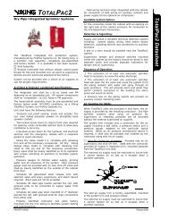
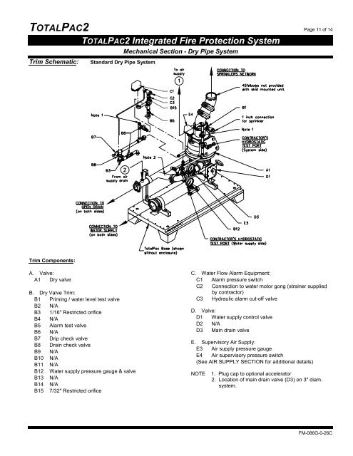
TOTALPAC2 Page 11 of 14Trim Schematic:TOTALPAC2 Integrated Fire Protection SystemStandard <strong>Dry</strong> Pipe SystemMechanical Section - <strong>Dry</strong> Pipe SystemTrim Components:A. Valve:A1 <strong>Dry</strong> valveB. <strong>Dry</strong> Valve Trim:B1 Priming / water level test valveB2 N/AB3 1/16" Restricted orificeB4 N/AB5 Alarm test valveB6 N/AB7 Drip check valveB8 Drain check valveB9 N/AB10 N/AB11 N/AB12 Water supply pressure gauge & valveB13 N/AB14 N/AB15 7/32" Restricted orificeC. Water Flow Alarm Equipment:C1 Alarm pressure switchC2 Connection to water motor gong (strainer suppliedby contractor)C3 Hydraulic alarm cut-off valveD. Valve:D1 Water supply control valveD2 N/AD3 Main drain valveE. Supervisory Air Supply:E3 Air supply pressure gaugeE4 Air supervisory pressure switch(See AIR SUPPLY SECTION for additional details)NOTE1. Plug cap to optional accelerator2. Location of main drain valve (D3) on 3" diam.system.FM-086G-0-26C