ABCs of ADCs - Analog-to-Digital Converter Basics (PDF)
ABCs of ADCs - Analog-to-Digital Converter Basics (PDF)
ABCs of ADCs - Analog-to-Digital Converter Basics (PDF)

Create successful ePaper yourself
Turn your PDF publications into a flip-book with our unique Google optimized e-Paper software.
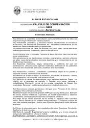
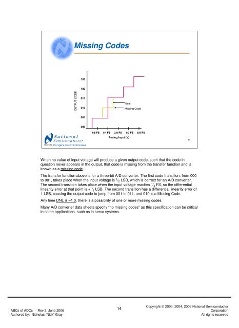
Missing Codes101100OUTPUT CODE011010IdealMissing Code0010001/8 FS 1/4 FS 3/8 FS 1/2 FS 5/8 FS<strong>Analog</strong> Input (V)14NCG 9/99When no value <strong>of</strong> input voltage will produce a given output code, such that the code inquestion never appears in the output, that code is missing from the transfer function and isknown as a missing code.The transfer function above is for a three-bit A/D converter. The first code transition, from 000<strong>to</strong> 001, takes place when the input voltage is 1 / 2 LSB, which is correct for an A/D converter.The second transition takes place when the input voltage reaches 1 / 4 FS, so the differentiallinearity error at that point is + 1 / 2 LSB. The second transition has a differential linearity error <strong>of</strong>1 LSB, causing the output code <strong>to</strong> jump from 001 <strong>to</strong> 011, and 010 is a Missing Code.Any time DNL is –1.0, there is a possibility <strong>of</strong> one or more missing codes.Many A/D converter data sheets specify “no missing codes” as this specification can be criticalin some applications, such as in servo systems.<strong>ABCs</strong> <strong>of</strong> <strong>ADCs</strong> - Rev 3, June 2006Authored by: Nicholas “Nick” Gray14Copyright © 2003, 2004, 2006 National Semiconduc<strong>to</strong>rCorporationAll rights reserved