ABCs of ADCs - Analog-to-Digital Converter Basics (PDF)
ABCs of ADCs - Analog-to-Digital Converter Basics (PDF)
ABCs of ADCs - Analog-to-Digital Converter Basics (PDF)

Create successful ePaper yourself
Turn your PDF publications into a flip-book with our unique Google optimized e-Paper software.
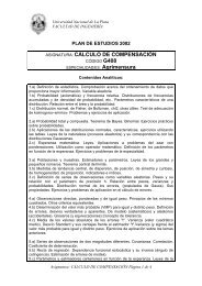
Better Conditioning Circuitry22 220Input-47ADC Input220+22pF6247+5V4302K3.9 nF-5V43This is a much better solution, The amplifier is operated at a gain <strong>of</strong> about 11.5 (don’t forgetthe effect <strong>of</strong> the 430-Ohm resis<strong>to</strong>r on gain!) and the input is padded down so that the overallgain from input <strong>to</strong> output is about 2. The amplifier is happy with the high gain, but take care <strong>to</strong>watch gain bandwidth requirements.The amplifier is decoupled from the ADC input with a simple RC. The capaci<strong>to</strong>r is generallychosen such that its value is about ten times the ADC input capacitance when the ADC is inthe sample or track mode, then the resis<strong>to</strong>r is chosen such that the pole frequency is thesample rate. When calculating the pole frequency, be sure <strong>to</strong> include the ADC inputcapacitance when the ADC is in the sample or track mode. This is for converters with inputfrequency less than half the sample rate.For undersampling applications, where the input frequency is higher than the sample rate,genereally we do not add an input capaci<strong>to</strong>r, but we do use a series resis<strong>to</strong>r <strong>of</strong> about 10 <strong>to</strong> 22Ohms.<strong>ABCs</strong> <strong>of</strong> <strong>ADCs</strong> - Rev 3, June 2006Authored by: Nicholas “Nick” Gray43Copyright © 2003, 2004, 2006 National Semiconduc<strong>to</strong>rCorporationAll rights reserved