ABCs of ADCs - Analog-to-Digital Converter Basics (PDF)
ABCs of ADCs - Analog-to-Digital Converter Basics (PDF)
ABCs of ADCs - Analog-to-Digital Converter Basics (PDF)

Create successful ePaper yourself
Turn your PDF publications into a flip-book with our unique Google optimized e-Paper software.
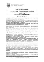
THD - Total HarmonicDis<strong>to</strong>rtion<strong>Analog</strong>SpectrumAnalyzerPure Sine WaveFrequency XXSquare WaveFrequency X<strong>Analog</strong>SpectrumAnalyzerX 3X 5XA/DFFTHarmonic Dis<strong>to</strong>rtionPure Sine WaveFrequency XX 2X 3X 4X 5X19THD gives an indication <strong>of</strong> a circuit’s linearity in terms <strong>of</strong> its effect on the harmonic content <strong>of</strong> asignal. An ideal, spectrally-pure sine wave has one frequency component. A complex signalsuch as music or speech has multiple frequency components. A square wave contains oddharmonics with specific amplitude and phase relationships. Ideally, a signal processing systemwill not add or subtract any harmonic components (unless that is the intended function <strong>of</strong> thesignal processor). Non-linearities in a converter’s transfer function, however, will produceharmonics that were not present in the original signal. Symmetrical non-linearities tend <strong>to</strong>produce harmonics at odd multiples <strong>of</strong> the input frequency, half rave rectification tends <strong>to</strong>produce even harmonics, while all other non-linearities tend <strong>to</strong> produce harmonics at allmultiples <strong>of</strong> the input frequency.THD is the ratio <strong>of</strong> the rms <strong>to</strong>tal <strong>of</strong> the first given number harmonic components <strong>to</strong> the RMSvalue <strong>of</strong> the output signal and relates the RMS sum <strong>of</strong> the amplitudes <strong>of</strong> the harmonics <strong>to</strong> theamplitude <strong>of</strong> the fundamental:THD =V f2 2 + V f3 2 + . . . + V fn2V f12where V f1 is the fundamental amplitude, V f2 is the second harmonic amplitude, etc.As a practical matter, there is no such thing as a completely linear input <strong>to</strong> output transferfunction. This non-linearity leads <strong>to</strong> output dis<strong>to</strong>rtion. As the input signal swing increases inamplitude, the output becomes more and more dis<strong>to</strong>rted. The result is an increase in dis<strong>to</strong>rtionas the input amplitude increases.THD performance degrades with increasing frequency because the effects <strong>of</strong> jitter get worseand because the input circuitry becomes slew limited.THD can be expressed as a percentage or in dB.<strong>ABCs</strong> <strong>of</strong> <strong>ADCs</strong> - Rev 3, June 2006Authored by: Nicholas “Nick” Gray19Copyright © 2003, 2004, 2006 National Semiconduc<strong>to</strong>rCorporationAll rights reserved