Compool to EasyTouch Upgrade Manual Rev B 03-15-2010 - Pentair
Compool to EasyTouch Upgrade Manual Rev B 03-15-2010 - Pentair
Compool to EasyTouch Upgrade Manual Rev B 03-15-2010 - Pentair
- No tags were found...

You also want an ePaper? Increase the reach of your titles
YUMPU automatically turns print PDFs into web optimized ePapers that Google loves.
<strong>Upgrade</strong>MODES OF OPERATIONAu<strong>to</strong>: Indoor control panel and other remote devices operate system.Service but<strong>to</strong>ns on this panel operate system.Other remote devices are disabled.Time Out: Service but<strong>to</strong>ns on this panel operate equipment forthree hours, then settings return <strong>to</strong> Au<strong>to</strong> mode.AUTOHEATERS A 95 / 100 FAIN 09 0 AMPoolSpaFill (Spillway)DrainVALVESMENUHEATER SOLARResetSELECTFILTERPUMPAUX 1AUX 2AUX 3AUX 4AUX 5AUX 6AUX 7<strong>Upgrade</strong>MODES OF OPERATIONAu<strong>to</strong>: Indoor control panel and other remote devices operate system.Service but<strong>to</strong>ns on this panel operate system.Other remote devices are disabled.Time Out: Service but<strong>to</strong>ns on this panel operate equipment forthree hours, then settings return <strong>to</strong> Au<strong>to</strong> mode.AUTOHEATERS A 95 / 100 FAIN 09 0 AMMENU SELECTFILTERPUMPPoolSpaFill (Spillway)AUX 1DrainVALVESAUX 2AUX 3HEATER SOLARResetAUX 4AUX 5AUX 6AUX 7<strong>Compool</strong> ® <strong>to</strong> <strong>EasyTouch</strong> ®Pool and Spa Control System <strong>Upgrade</strong>Installation and User’s GuideIMPORTANT SAFETY INSTRUCTIONSREAD AND FOLLOW ALL INSTRUCTIONSSAVE THESE INSTRUCTIONS
IMPORTANT INFORMATIONHow <strong>to</strong> change your <strong>Compool</strong>/<strong>EasyTouch</strong> <strong>Upgrade</strong>system <strong>to</strong> a “Single Body” systemConfiguring <strong>Compool</strong>/<strong>EasyTouch</strong> as a SINGLE BODY SYSTEMThe <strong>Compool</strong> <strong>EasyTouch</strong> <strong>Upgrade</strong> circuit board is fac<strong>to</strong>ry configured and ready <strong>to</strong> operate as aSHARED EQUIPMENT system (Jumper J25 = ON). To change the <strong>Compool</strong> <strong>EasyTouch</strong> <strong>Upgrade</strong> board<strong>to</strong> operate a SINGLE BODY system, first remove Jumper 25 (place the jumper on one of the pins) anderase the EEPROM (see page 49).To change <strong>Compool</strong> <strong>EasyTouch</strong> circuit board:Getting ThereMENU ▼ SETTINGS ▼ Erase EEPROM▲Erase EEPROM1. Write down your <strong>Compool</strong> system settings and connections (e.g. filter pump schedules,auxiliary connection for lights, spa jets etc.).2. Change system <strong>to</strong> SINGLE BODY system (jumper OFF): Remove circuit board JumperJ25. Place the jumper on one of the pins. J25 is located in the upper/center of the circuitboard (see page 76).3. Erase the circuit board EEPROM: Power up the <strong>Compool</strong> <strong>EasyTouch</strong> <strong>Upgrade</strong> circuitboard. To erase the EEPROM, press MENU > SETTINGS > Erase EEPROM and followthe screen prompts as shown below:Erase EEPROMErase ALL? No (Yes)Up/Down but<strong>to</strong>n: Select Yes.Erase EEPROMAre You Sure?No (Yes)Right but<strong>to</strong>n: The message “Erase EEPROM Are You Sure? No” isdisplayed.Up/Down but<strong>to</strong>n: Select Yes.AUTO HEATERSPA 95°F / 100°FAIR 70°FMON 09:30 AMRight but<strong>to</strong>n: Press this but<strong>to</strong>n <strong>to</strong> erase system data and res<strong>to</strong>re thefac<strong>to</strong>ry defaults. The display will go blank, then the main screen will bedisplayed.4. Continue <strong>to</strong> setup your system using the <strong>EasyTouch</strong> menu (see page 14).© <strong>2010</strong> <strong>Pentair</strong> Water Pool and Spa, Inc. All rights reserved.1620 Hawkins Ave., Sanford, NC 27330 • (919) 566-800010951 West Los Angeles Ave., Moorpark, CA 93021 • (800) 553-5000<strong>EasyTouch</strong>®, <strong>Compool</strong>®, IntelliChlor®, IntelliFlo®, MagicStream®, ThermalFlo®, QuickTouch®, IntelliBrite®,SAm®, SAL®, FIBERworks®, Pho<strong>to</strong>n Genera<strong>to</strong>r®, and <strong>Pentair</strong> Water Pool and Spa® are trademarks and/orregistered trademarks of <strong>Pentair</strong> Water Pool and Spa, Inc. and/or its affiliated companies in the United States and/or other countries. Unless noted, names and brands of others that may be used in this document are not used <strong>to</strong>indicate an affiliation or endorsement between the proprie<strong>to</strong>rs of these names and brands and <strong>Pentair</strong> Water Pooland Spa, Inc. Those names and brands may be the trademarks or registered trademarks of those parties or others.P/N 521102 - <strong>Rev</strong> B - <strong>03</strong>/<strong>15</strong>/<strong>2010</strong>
iContentsIMPORTANT SAFETY PRECAUTIONS ........................................................................................................ iii<strong>EasyTouch</strong> System Kit Contents................................................................................................................... vAccessory Equipment ................................................................................................................................... vTechnical Support ......................................................................................................................................... vHow <strong>to</strong> Change the system <strong>to</strong> a SINGEL BODY system ............................................................................ vSection 1 - <strong>Compool</strong> <strong>to</strong> <strong>EasyTouch</strong> Pool and Spa Control System <strong>Upgrade</strong> Overview .......................... 1<strong>Compool</strong>® <strong>EasyTouch</strong>® Pool and Spa Control System <strong>Upgrade</strong> Overview.................................................... 1<strong>Compool</strong> upgrade systems ....................................................................................................................... 1Operating <strong>EasyTouch</strong> .................................................................................................................................... 1IntelliChlor® Electronic Chlorine Genera<strong>to</strong>r.................................................................................................... 1<strong>Compool</strong> <strong>EasyTouch</strong> <strong>Upgrade</strong> System Overview ........................................................................................... 2<strong>Compool</strong> <strong>EasyTouch</strong> <strong>Upgrade</strong> Control Panel .................................................................................................. 3Comppol/<strong>EasyTouch</strong> <strong>Upgrade</strong> Controls and But<strong>to</strong>ns...................................................................................... 3iS4 Spa-Side Remote Controller (Optional) .................................................................................................... 6QuickTouch® QT4 Wireless Controller (Optional) .......................................................................................... 6iS10 Spa-Side Remote Controller (Optional) .................................................................................................. 6<strong>EasyTouch</strong> Indoor and Wireless Control Panel (Optional) ............................................................................... 7<strong>Compool</strong>/<strong>EasyTouch</strong> <strong>Upgrade</strong> Outdoor Control Panel Operating Modes ......................................................... 8Quick Start - Spa and Pool Operations (Shared Equipment).......................................................................... 9Heat your spa or pool .................................................................................................................................... 9Adjust your spa or pool heat settings ........................................................................................................ 9Switch on lights manually and synchronize light colors ................................................................................. 10Using the Once Only timer feature ................................................................................................................ 10Schedule start and s<strong>to</strong>p times for equipment ................................................................................................ 11Program your Spa or Pool ......................................................................................................................... 11Schedules ..................................................................................................................................................... 11Setting the Egg Timer Feature .................................................................................................................. 12Section 2 - Setting up the <strong>Compool</strong>/<strong>EasyTouch</strong> <strong>Upgrade</strong> System ........................................................... 13<strong>EasyTouch</strong> Menus ........................................................................................................................................ 14Main Screen.................................................................................................................................................. 16Feature Circuits Menu ................................................................................................................................... 17Lights Menu .................................................................................................................................................. 18The Color Swim and Color Set Lighting Features ...................................................................................... 18Setting up Lights....................................................................................................................................... 19Assign the Light Circuit Name and Function ............................................................................................. 19Setting up IntelliBrite Light Circuits ............................................................................................................... 20Lights Menu .............................................................................................................................................. 20Modes (IntelliBrite Color light shows, Color Swim, Color Set) .................................................................... 20Modes (Color Swim).................................................................................................................................. 20Modes (Color Set) ..................................................................................................................................... 21Colors ....................................................................................................................................................... 21Hold/Recall ............................................................................................................................................... 21All On / All Off (Lights Menu) .................................................................................................................... 21Sync ......................................................................................................................................................... 21Setting up SAM, SAL, PG2000, Color Wheel Lights.................................................................................. 22Config ....................................................................................................................................................... 22Setting up MagicStream Laminars ................................................................................................................ 23Using the MagicStream Laminar Features ................................................................................................ 24Heat Menu .................................................................................................................................................... 25Pool Temp/Src ........................................................................................................................................... 25Spa Temp/Src ........................................................................................................................................... 25Delay Cancel Menu ....................................................................................................................................... 26<strong>Compool</strong>/<strong>EasyTouch</strong> Pool and Spa Control System <strong>Upgrade</strong> Installation and User’s Guide
iiContents (Continued)Schedules Menu ........................................................................................................................................... 27Using the Schedules menu ....................................................................................................................... 27Schedule your spa/pool pump <strong>to</strong> turn on ................................................................................................... 28Using the Once Only feature..................................................................................................................... 29Using the Egg Timer (countdown) Feature ................................................................................................. 30Settings Menu: Clock .................................................................................................................................... 31Settings Menu: IntelliFlo® VS and VF .......................................................................................................... 32IntelliFlo® VS pump ...................................................................................................................................... 32IntelliFlo® VS pump ...................................................................................................................................... 33Settings Menu: IntelliChlor ............................................................................................................................ 35Settings Menu: ThermalFlo® Heat Pump ...................................................................................................... 36Settings Menu: Circuit Names ....................................................................................................................... 37Hi-Temp/Lo-Temp Controls for Single Body System ...................................................................................... 37<strong>EasyTouch</strong> Circuit Names ............................................................................................................................. 38Settings Menu: Circuit Functions................................................................................................................... 39Freeze Protection .......................................................................................................................................... 39Preset Circuit Functions ................................................................................................................................ 40Settings Menu: Cus<strong>to</strong>m Names..................................................................................................................... 41Settings Menu: Valves................................................................................................................................... 41Settings Menu: 2-Speed Pump ...................................................................................................................... 42Settings Menu: Solar ..................................................................................................................................... 42Settings Menu: Delays .................................................................................................................................. 43Settings Menu: F° / C° (Fahrenheit/Celsius) .................................................................................................. 44Settings Menu: iS4 Spa-Side Remote Controller ........................................................................................... 44Settings Menu: iS10 Spa-Side Remote Controller.......................................................................................... 45Settings Menu: iSx Pump Cntrl ..................................................................................................................... 46Assign iSx Pump Cntrl ............................................................................................................................. 46Settings Menu: QuickTouch (QT4) Wireless Remote ..................................................................................... 47Settings Menu: Man Heat (Off/On) ................................................................................................................ 48Settings Menu: Calibration ............................................................................................................................ 48Settings Menu: Erase EEPROM (Erase System Memory) ............................................................................ 49Settings Menu: Set Password ....................................................................................................................... 49Settings Menu: Wireless Addr ....................................................................................................................... 50Spa Side [Off/On] ......................................................................................................................................... 51Diagnostics Menu: Software <strong>Rev</strong>................................................................................................................... 51Diagnostics Menu: Bootloader <strong>Rev</strong>................................................................................................................ 51Diagnostics Menu: Self Test .......................................................................................................................... 52Diagnostics Menu: Chlorina<strong>to</strong>r ....................................................................................................................... 53Diagnostics Menu: Water Temp ...................................................................................................................... 53Diagnostics Menu: Solar Temp ...................................................................................................................... 53Diagnostics Menu: Air Temp .......................................................................................................................... 54Diagnostics Menu: Cir Name: [Off/On] .......................................................................................................... 54Diagnostics Menu: Reset System ................................................................................................................. 54Diagnostics Menu: Flash Update ................................................................................................................... 54Section 3 - Troubleshooting ....................................................................................................................... 55Troubleshooting ............................................................................................................................................. 55Frequently Asked Questions (FAQ) ............................................................................................................... 55<strong>EasyTouch</strong> Error Messages .......................................................................................................................... 56Self Test Error Codes .................................................................................................................................... 56Error Code Table ............................................................................................................................................ 56Maximum Programs Exceeded ..................................................................................................................... 57IntelliChlor Error Messages ........................................................................................................................... 57System Problem Diagnosis ........................................................................................................................... 58<strong>Compool</strong>/<strong>EasyTouch</strong> Pool and Spa Control System <strong>Upgrade</strong> Installation and User’s Guide
iiiContents (Continued)First Time System Start-Up .......................................................................................................................... 61System Test .................................................................................................................................................. 61Testing the Auxiliary Relays .......................................................................................................................... 61Setting up the <strong>EasyTouch</strong> wireless control panel for the first time ................................................................. 62Setting up the <strong>EasyTouch</strong> wireless control panel ........................................................................................... 62Synchronizing control panels ........................................................................................................................ 63Wiring ThermalFlo <strong>to</strong> <strong>EasyTouch</strong> ................................................................................................................... 63Wiring Description ......................................................................................................................................... 63Section 4 - <strong>Compool</strong>/<strong>EasyTouch</strong> <strong>Upgrade</strong> Kit Installation ........................................................................ 65<strong>Compool</strong>/<strong>EasyTouch</strong> <strong>Upgrade</strong> Kits ................................................................................................................ 65<strong>Compool</strong>/<strong>EasyTouch</strong> <strong>Upgrade</strong> Models<strong>Compool</strong>/<strong>EasyTouch</strong> <strong>Upgrade</strong> Models (Single Body Systems) ................................................................ 66<strong>Compool</strong>/<strong>EasyTouch</strong> <strong>Upgrade</strong> Models (Shared Equipment Systems) ...................................................... 67Installing <strong>Compool</strong>/<strong>EasyTouch</strong> <strong>Upgrade</strong> Control Panel (with or without Transformer Kit) ................................. 68<strong>Compool</strong> Power Center (without sub-panel) .................................................................................................... 68<strong>Compool</strong> Load Center (with breaker sub-panel) .............................................................................................. 72Installing the <strong>Compool</strong>/<strong>EasyTouch</strong> <strong>Upgrade</strong> Control Panel(<strong>Compool</strong> Load Center with sub-panel) .......................................................................................................... 74<strong>Compool</strong>/<strong>EasyTouch</strong> <strong>Upgrade</strong> Circuit board Wiring Diagram ......................................................... 76<strong>Compool</strong> 3810 Circuit board Wiring Diagram ................................................................................. 77<strong>Compool</strong>/<strong>EasyTouch</strong> Pool and Spa Control System <strong>Upgrade</strong> Installation and User’s Guide
ivIMPORTANT WARNINGS AND SAFETY PRECAUTIONSSERIOUS BODILY INJURY OR DEATH CAN RESULT IF THIS PRODUCTIS NOT INSTALLED ANDUSED CORRECTLY.INSTALLERS, POOL OPERATORS AND POOL OWNERS MUST READ THESE WARNINGS ANDALL INSTRUCTIONS BEFORE USING THIS PRODUCT.This control system is intended for use in swimming pool applications.Most states and local codes regulate the construction, installation, and operation of public pools andspas, and the construction of residential pools and spas. It is important <strong>to</strong> comply with these codes,many of which directly regulate the installation and use of this product. Consult your local building andhealth codes for more information.IMPORTANT NOTICE - Attention Installer: This Installation and User’s Guide (“Guide”) contains importantinformation about the installation, operation and safe use of this product. This Guide should be given <strong>to</strong> theowner and/or opera<strong>to</strong>r of this equipment.Before installing this product, read and follow all warning notices and instructions in this Guide.Failure <strong>to</strong> follow warnings and instructions can result in severe injury, death, or property damage. Call(800) 831-7133 for additional free copies of these instructions. Please refer <strong>to</strong> www.pentair.com formore information related <strong>to</strong> this product.Water temperature in excess of 100° F (37.7° C) may be hazardous <strong>to</strong> your health. Prolonged immersionin hot water may induce hyperthermia. Hyperthermia occurs when the internal temperature of the bodyreaches a level several degrees above normal body temperature of 98.6° F. (37° C.). Effects ofhyperthermia include: (1) Unawareness of impending danger. (2) Failure <strong>to</strong> perceive heat. (3) Failure <strong>to</strong>recognize the need <strong>to</strong> leave the spa. (4) Physical inability <strong>to</strong> exit the spa. (5) Fetal damage in pregnantwomen. (6) Unconsciousness resulting in danger of drowning. The use of alcohol, drugs, or medicationcan greatly increase the risk of fatal hyperthermia in hot tubs and spas.To reduce the risk of injury, do not permit children <strong>to</strong> use or operate this sand filter.When setting up pool water turnovers or flow rates the opera<strong>to</strong>r must consider local codes governingturnover as well as disinfectant feed ratios.DO NOT increase pump size; this will increase the flow rate through the system and may exceed themaximum flow rate stated on the drain cover.Water temperature in excess of 100 degrees Fahrenheit may be hazardous <strong>to</strong> your health. Prolongedimmersion in hot water may induce hyperthermia. Hyperthermia occurs when the internal temperatureof the body reaches a level several degrees above normal body temperature of 98.6° F (37° C). Thesymp<strong>to</strong>ms of hyperthermia include drowsiness, lethargy, dizziness, fainting, and an increase in theinternal temperature of the body. The effects of hyperthermia include: 1) Unawareness of impendingdanger. 2) Failure <strong>to</strong> perceive heat. 3) Failure <strong>to</strong> recognize the need <strong>to</strong> leave the spa. 4) Physicalinability <strong>to</strong> exit the spa. 5) Fetal damage in pregnant women. 6) Unconsciousness resulting in dangerof drowning.To reduce the risk of injury, do not permit children <strong>to</strong> use this product unless they are closelysupervised at all times.The use of alcohol, drugs, or medication can greatly increase the risk of fatal hyperthermia inhot tubs and spas.Control System is intended <strong>to</strong> control heaters with built-in high limit circuits ONLY. Failure <strong>to</strong> do somay cause property damage or personal injury.Do not use this product <strong>to</strong> control an au<strong>to</strong>matic pool cover. Swimmers may become entrappedunderneath the cover.<strong>Compool</strong>/<strong>EasyTouch</strong> Pool and Spa Control System <strong>Upgrade</strong> Installation and User’s Guide
vIMPORTANT WARNINGS AND SAFETY PRECAUTIONSFor units intended for use in other than single-family dwellings, a clearly labeled emergency switch shallbe provided as part of the installation. The switch shall be readily accessible <strong>to</strong> the occupants and shallbe installed at least 10 feet (3.05 m) away, adjacent <strong>to</strong>, and within sight of, the unit.Except for listed spa-side remote controls, install a minimum of five (5) feet from the inside wall of thepool and spa.TO PREVENT ELECTROCUTION: INSTALL THE POWER CENTER OR LOAD CENTER AT LEASTFIVE (5) FEET (1.2M) FROM INSIDE WALL OF POOL OR SPA.Two Speed Pump Controls Notice (Title 20 Compliance)Please read the following important Safety Instructions (See page 42 for pump speed setup)When using two-speed pumps manufactured on or after January 1, 2008, the pump’s default circulation speed MUST beset <strong>to</strong> the LOWEST SPEED, with a high speed overide capability being for a temporary period not <strong>to</strong> exceed one normalcycle, or two hours, whichever is less.Important Installation Information1. All work must be performed by a licensed electrician, and must conform <strong>to</strong> all national, state,and local codes. The electrical supply for this product must include a suitably rated switch orcircuit breaker <strong>to</strong> open all ungrounded supply conduc<strong>to</strong>rs <strong>to</strong> comply with National ElectricalCode (NEC), NFPA 70 (including Artical 680) or the Canadian Electrical Code (CEC), CSAC22.1. The disconnecting means must be readily accessible <strong>to</strong> the tub occupant butinstalled at least 5 ft. (1.52 m) from the inside wall of the Pool, Spa, or Hot Tub.2. Install <strong>to</strong> provide drainage of compartment for electrical components.3. Install enclosure with conduit holes down.4. If this system is used <strong>to</strong> control underwater lighting fixtures, a ground-fault circuit interrupter(GFCI) must be provided for these fixtures. Conduc<strong>to</strong>rs on the load side of the ground-faultcircuit-interrupter shall not occupy conduit, junction boxes or enclosures containing otherconduc<strong>to</strong>rs unless such conduc<strong>to</strong>rs are also protected by a ground-fault circuit-interrupter.Refer <strong>to</strong> local codes for details.5. A terminal bar stamped is located inside the supply terminal box. To reduce the risk ofelectric shock, this terminal must be connected <strong>to</strong> the grounding means provided in theelectric supply service panel with a continuous copper wire equivalent in size <strong>to</strong> the circuitconduc<strong>to</strong>rs supplying this equipment (no smaller than 12 AWG or 3.3 mm). The bondinglug(s) provided on this unit are intended <strong>to</strong> connect a minimum of one No. 8 AWG for USinstallation and two No. 6 AWG for Canadian installations solid copper conduc<strong>to</strong>r betweenthis unit and any metal equipment, metal enclosures or electrical equipment, metal waterpipe, or conduit within 5 feet (1.5 m) of the unit.6. Use 14 AWG <strong>to</strong> 6 AWG, 60° / 75° C Copper conduc<strong>to</strong>rs for all field wiring.7. Electrical rating: 120/240 VAC <strong>15</strong>0 AMP Single Phase (3 wire).8. The input line <strong>to</strong> the control panel should be protected by a 240 VAC CIRCUIT BREAKERrated at NO MORE then <strong>15</strong>0 Amperes maximum.<strong>Compool</strong>/<strong>EasyTouch</strong> Pool and Spa Control System <strong>Upgrade</strong> Installation and User’s Guide
vi<strong>Compool</strong> <strong>to</strong> <strong>EasyTouch</strong> <strong>Upgrade</strong> System Kit ContentsThe following items are included in the <strong>Compool</strong> <strong>to</strong> <strong>EasyTouch</strong> <strong>Upgrade</strong> System kit.• <strong>Compool</strong> To <strong>EasyTouch</strong> <strong>Upgrade</strong> Kit (P/N 521107) - For upgrading CP3xxx systems• <strong>Compool</strong> To <strong>EasyTouch</strong> <strong>Upgrade</strong> Kit with Transformer (P/N 521247) - For upgrading Cp100, Cp1000,Cp2000 system.• Temperature sensor with 20 foot cable, o-ring and hose clamp (P/N 520272) - Uses for the watertemperature sensor• Temperature sensor with 40 inch cable - Used for the air termperature sensor• <strong>Compool</strong> <strong>to</strong> <strong>EasyTouch</strong> <strong>Upgrade</strong> Pool and Spa Control System Installation and User’s Guide(this manual)Optional Equipment• IntelliChlor Electronic Chlorine Genera<strong>to</strong>r Electrolytic Cell - IC20 (P/N 520554),IC40 (P/N 520555) or IC60 (P/N 521105)Accessory EquipmentPOWER ON<strong>EasyTouch</strong> 8 Indoor ControlPanel Kit (P/N 520549)<strong>EasyTouch</strong> Wireless Control Panel(8 circuit) Kit (P/N 520547)iS10 Spa-SideRemote Controller (P/N 520149)iS4 Spa-Side RemoteController (P/N 520094)QuickTouch ® wireless remote controllerKit (P/N 520148)<strong>EasyTouch</strong> Accessories (continued)<strong>EasyTouch</strong> Indoor Control Panel, 8 Circuits (P/N 520549)<strong>EasyTouch</strong> Wireless Control Panel, 8 circuits (P/N 520547)iS4 Four-Function Spa-Side remote, <strong>15</strong>0 ft. cable (P/N 520094)iS10 Ten-Function Spa-Side remote, <strong>15</strong>0 ft. cable (P/N 520149)QuickTouch four-function wireless remote kit with transceiver assembly (P/N 520148)IntelliChlor Acid Cleaning Kit (P/N 520670)IntelliChlor Spacer pass-through cell for new pool start-up (P/N 520588)Technical SupportSanford, North Carolina (8 A.M. <strong>to</strong> 5 P.M.)Phone: (800) 831-7133 - Fax: (919) 566-8920Moorpark, California (8 A.M. <strong>to</strong> 5 P.M.)Phone: (800) 831-7133 - Fax: (805) 553-55<strong>15</strong>visit www.pentairpool.com and www.staritepool.com<strong>Compool</strong>/<strong>EasyTouch</strong> Pool and Spa Control System <strong>Upgrade</strong> Installation and User’s Guide
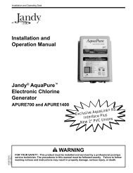
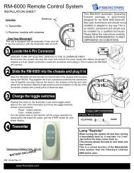
1Section 1Overview<strong>Compool</strong> ® <strong>EasyTouch</strong> ® Pool and Spa Control System <strong>Upgrade</strong> OverviewWelcome <strong>to</strong> the <strong>Compool</strong> <strong>EasyTouch</strong> upgrade Pool and Spa Control system − The next generation inau<strong>to</strong>matic control systems. Your <strong>Compool</strong> <strong>EasyTouch</strong> upgrade system opens up a wide range of au<strong>to</strong>mationfeatures. Your <strong>EasyTouch</strong> eight auxiliary system allows you <strong>to</strong> au<strong>to</strong>matically control all of your spa and pooldaily operations. Pool and spa service operations can be manually controlled from the <strong>EasyTouch</strong> outdoorcontrol panel located at the pool equipment pad. Also available is the optional Indoor Control Panel andWireless Control Panel which allows au<strong>to</strong>matic control of pool and spa operations from inside your home oroutside around your pool area.The <strong>EasyTouch</strong> eight auxiliary circuit system is fac<strong>to</strong>ry configured <strong>to</strong> operate as a “shared” equipment systemor it can be configured as a “single body” system (see page 64). For <strong>EasyTouch</strong> menu settings, see page 14.The <strong>EasyTouch</strong> eight auxiliary system can control high voltage (120 VAC / 240 VAC) equipment, au<strong>to</strong>maticvalve actua<strong>to</strong>rs, pumps, lighting, a conventional heater or a solar heating system and the optional IntelliChlorsalt chlorine genera<strong>to</strong>r.<strong>Compool</strong> upgrade systemsThe following <strong>Compool</strong> systems can be upgraded <strong>to</strong> the <strong>Compool</strong>/<strong>EasyTouch</strong> system: <strong>Compool</strong> CP3xxxmodels (see page 66 and 67), also <strong>Compool</strong> TimeMaster, CP/LX100, CP1000, CP2000 and CP3000 models.Note: To upgrade <strong>Compool</strong> TimeMaster, CP/LX100, CP1000, CP2000 models requires <strong>Compool</strong>/<strong>EasyTouch</strong> control panel upgrade kit with transformer P/N 521247). Otherwise CP3xxx systemsrequire P/N 521107. For <strong>Compool</strong>/<strong>EasyTouch</strong> Control Panel with or without Transformer Kit installationinstructions, see page 65).Operating <strong>EasyTouch</strong>The <strong>EasyTouch</strong> system is designed <strong>to</strong> au<strong>to</strong>matically control your pool and spa equipment, lights and otheroptional equipment. However, you can also manually control all <strong>EasyTouch</strong> system operations from the outdoorcontrol panel. Using the “Mode” but<strong>to</strong>n, the system can be switched from “Au<strong>to</strong>” mode (normal operatingmode) <strong>to</strong> “Service” mode for manual operation and service purposes. Using the outdoor control panel but<strong>to</strong>nsyou can manually override any au<strong>to</strong>matic settings. If required, the <strong>EasyTouch</strong> outdoor control panel can bepassword protected. To access a password protected control panel, the correct four digit password must beentered before access is granted (see page 49).IntelliChlor ® Electronic Chlorine Genera<strong>to</strong>rThe optional IntelliChlor salt chlorination system allows the <strong>EasyTouch</strong>system <strong>to</strong> au<strong>to</strong>matically control water sanitization by using a lowconcentration of salt (sodium chloride) in the pool and spa water. TheIntelliChlor is enabled from the “IntelliChlor” Settings menu (see page 35).IntelliChlor au<strong>to</strong>matically converts the salt in<strong>to</strong> free chlorine which eliminatesbacteria and algae in the pool and spa water. The chlorine will then revertback <strong>to</strong> sodium chloride after killing the bacteria. The outcome of thiscontinuous cycle, practically eliminates the need <strong>to</strong> use sanitizing chemicals inthe pool/spa water. When the pool and spa water is replenished due <strong>to</strong>IntelliChlor ElectronicChlorine Genera<strong>to</strong>rbackwashing or draining, more salt may need <strong>to</strong> be added <strong>to</strong> the pool/spa water. IntelliChlor model IC20 (P/N520554/520556) is designed for swimming pools up <strong>to</strong> 20,000 U.S. gallons (75,000 liters). Model IC40 (P/N520555/520556) is designed for swimming pools up <strong>to</strong> 40,000 U.S. gallons (<strong>15</strong>1,000 liters). IC60 Cell (P/N521105): Designed for pools up <strong>to</strong> 60,000 U.S. gallons (227,124 liters). The pool chlorination amounts mayvary depending on number of pool occupants, temperature, environment conditions, rainfall and other elementsthat might affect the pool water.<strong>Compool</strong>/<strong>EasyTouch</strong> Pool and Spa Control System <strong>Upgrade</strong> Installation and User’s Guide
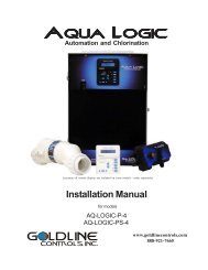
MODES OF OPERATIONAu<strong>to</strong>: Indoor control panel and other remote devices operate system.Service: Service but<strong>to</strong>ns on this panel operate system.Other remote devices are disabled.Time Out: Service but<strong>to</strong>ns on this panel operate equipment forthree hours, then settings return <strong>to</strong> Au<strong>to</strong> mode.VALVESHEATERResetPoolSpaFill (Spillway)MENUSOLARSELECTFILTERPUMPAUX 1AUX 2AUX 3AUX 4AUX 5AUX 6AUX 7MODE2<strong>Compool</strong> <strong>EasyTouch</strong> <strong>Upgrade</strong> System OverviewConnects <strong>to</strong><strong>Compool</strong>/<strong>EasyTouch</strong> <strong>Upgrade</strong> motherboard viaRJ12 Adapter or 4-position screw terminal<strong>EasyTouch</strong> IndoorControl Panel (P/N 520549)(Optional)Low Voltage (DC)circuit breakers<strong>EasyTouch</strong> WirelessControl Panel (8 circuit)(P/N 520547) (Optional)AUTOHEATERSPA 95 F / 100 FAIR 70 FMON 09:30 AMV<strong>Upgrade</strong>FDrain1• PumpsFilter, Cleaner, Spa Jet -1.5 HP 120 VAC3 HP 277 VAC20 FLA/120 LRA,120 VAC17 FLA/102 LRA, 277 VAC• Pool/Spa Lights1.5 KW 120 VAC Tungsten4.8 KW 240 VAC Tungsten20 AMP, 277 VAC BallastiS4 Spa-SideRemote (P/N 520094)(Optional)234567• Pool/Spa ValveSuction and return.24 VAC valve actua<strong>to</strong>r,shared equipment only• Auxiliary Valves(Qty. 2) A and BQuickTouch ® (QT4)wireless remoteController(P/N 520148)(Optional)<strong>Compool</strong> Power Center(shown without subpanel)• HeaterGas or electric• Relays20 AMP, 2 HP, 240 VAC30 AMP, 3 HP, 240 VACoptionalOptional equipmentiS10 Spa-SideRemote (P/N 520149)(Optional)Temperature Sensors(Water, Air andSolar optional)Electric Heater -Connects <strong>to</strong> plug J19 onmotherboardMain Power GFCI Panel 240 VAC 50AMP (40 AMP recommended 8 AWG)• IntelliChlor Salt ChlorineGenera<strong>to</strong>r (SCG)• IC20 P/N 520554/520556• IC40 P/N 520555/520556• CIC60 P/N 521105(see page 26)<strong>Compool</strong>/<strong>EasyTouch</strong> Pool and Spa Control System <strong>Upgrade</strong> Installation and User’s Guide
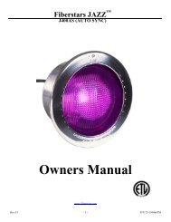
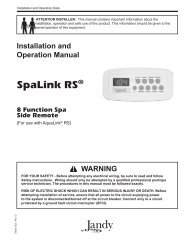
3<strong>Compool</strong> <strong>EasyTouch</strong> <strong>Upgrade</strong> Control PanelYour <strong>EasyTouch</strong> upgrade system can fully au<strong>to</strong>mate your pool, spa functions and any auxiliary circuits(additional pumps and lighting) from the <strong>EasyTouch</strong> upgrade outdoor control panel or from the optional<strong>EasyTouch</strong> indoor control panel and <strong>EasyTouch</strong> wireless control panel. The <strong>EasyTouch</strong> menu features let youcreate cus<strong>to</strong>mized schedules for your pool and spa equipment, heat temperatures, and chlorination settings <strong>to</strong>switch on and off at a set day and time. Scheduled au<strong>to</strong>matic operations can be performed at either theoutdoor control panel, the optional indoor control panel and wireless control panel. For maintenance andservice purposes, the outdoor control panel but<strong>to</strong>n allows manual control of all pool and spa operations. Formenu options, refer <strong>to</strong> “<strong>EasyTouch</strong> Menus,” on page 14. The following describes the outdoor control panelbut<strong>to</strong>ns, and LED indica<strong>to</strong>rs.➀➃➄➂MODES OF OPERATIONAu<strong>to</strong>: Indoor control panel and other remote devices operate system.Service: Service but<strong>to</strong>ns on this panel operate system.Other remote devices are disabled.Time Out: Service but<strong>to</strong>ns on this panel operate equipment forthree hours, then settings return <strong>to</strong> Au<strong>to</strong> mode.AUTOHEATERSPA 95 F / 100 FAIR 70 FMON 09:30 AM<strong>Upgrade</strong>MODE➆➁➇VMENUSELECTFILTERPUMPFPoolSpaFill (Spillway)AUX 1 1Drain➅➉VALVESAUX 2AUX 3AUX 4234➈HEATERSOLARAUX 55ResetAUX 66AUX 77Comppol/<strong>EasyTouch</strong> <strong>Upgrade</strong> Controls and But<strong>to</strong>ns➀➁➂<strong>Compool</strong>/<strong>EasyTouch</strong> <strong>Upgrade</strong> Outdoor Control PanelLiquid Crystal Display (LCD): The main system display consists of a 16 x 4 alphanumeric characterLCD with LED backlighting for easy viewing of the menu items and status messages. If necessary,press the Menu but<strong>to</strong>n twice <strong>to</strong> refresh the display.Up/Down but<strong>to</strong>ns: Use the Up and Down but<strong>to</strong>ns <strong>to</strong> scroll through the main menu items and <strong>to</strong>adjust or change settings. Use these but<strong>to</strong>ns after pressing the Menu but<strong>to</strong>n <strong>to</strong> access the main menuitems. While editing settings, press and hold the Up or Down but<strong>to</strong>n <strong>to</strong> fast forward or fast reversethrough settings and values.Left but<strong>to</strong>n: When in pool or spa mode use the Left and Right but<strong>to</strong>n <strong>to</strong> adjust the temperature level.Press the Left but<strong>to</strong>n <strong>to</strong> lower the set point water temperature. Press the Filter Pump (F) but<strong>to</strong>n <strong>to</strong>display the current water temperature. Use the Left but<strong>to</strong>n <strong>to</strong> scroll through sub-menu selections,setting and values. While editing settings, press and hold the Left but<strong>to</strong>n <strong>to</strong> fast reverse throughsettings and values.<strong>Compool</strong>/<strong>EasyTouch</strong> Pool and Spa Control System <strong>Upgrade</strong> Installation and User’s Guide
4Controls and but<strong>to</strong>ns (Continued)➃MENUMenu/back but<strong>to</strong>n: Use this but<strong>to</strong>n <strong>to</strong> access, save and exit from a current menu or sub-menusettings. Also, while in a menu or sub-menu items, use this but<strong>to</strong>n <strong>to</strong> go back <strong>to</strong> a previous menulevel or item. If no menu activity is detected after five minutes, the main screen is displayed. Allmenu settings are permanently saved and retained in the control panel even after power is removedfrom the control panel. Control panel but<strong>to</strong>ns are disabled while in the menu mode.➄➅SELECTRight but<strong>to</strong>n/SELECT: When in pool or spa mode use the Left and Right but<strong>to</strong>n <strong>to</strong> adjust thetemperature level. Press the Right but<strong>to</strong>n <strong>to</strong> raise the set point water temperature. Press the FilterPump (F) but<strong>to</strong>n <strong>to</strong> display the current water temperature. Use the Right but<strong>to</strong>n <strong>to</strong> select a sub-menuitem for editing. After pressing the Menu but<strong>to</strong>n <strong>to</strong> access the main menu items, use the Right but<strong>to</strong>n<strong>to</strong> select the menu item and access the sub-menu items for adjustment. While editing a settings,press and hold the Right but<strong>to</strong>n <strong>to</strong> fast forward through settings and values.Filter Pump (F) but<strong>to</strong>n/LED: Switches a single speed filter pump on and off in “Pool” or “Spa”mode. Press the Valves (V) but<strong>to</strong>n <strong>to</strong> <strong>to</strong>ggle between “Pool” and “Spa” mode and rotate valves. If“Heater” is enabled in the “Heat” menu (see page 25), pressing the Filter Pump but<strong>to</strong>n will alsoenable the selected heat source (Heater/Solar LED on). The default time before the filter pump willswitch off is 12 hours. This but<strong>to</strong>n operates in “Au<strong>to</strong>” or “Service” mode.Single-Speed Filter Pump: If the pump is currently off, press the Filter Pump but<strong>to</strong>n (LED on) <strong>to</strong>switch the pump on. Press the Filter Pump but<strong>to</strong>n again <strong>to</strong> switch the pump off. However, if theheater is operating, and a delay is enabled for valves, this allows the heater <strong>to</strong> cool down (heatercool-down), then when you press the F but<strong>to</strong>n <strong>to</strong> switch off the pump, only the heater will turn off,then the filter pump will au<strong>to</strong>matically switch off after 10 minutes <strong>to</strong> allow the heater <strong>to</strong> cool down.<strong>Pentair</strong> Water Pool and Spa ® heaters do not require a cool down time. To override the “heater cooldown,”press the Filter Pump but<strong>to</strong>n again <strong>to</strong> switch off the pump.Two-Speed Filter Pump: Press the Filter Pump but<strong>to</strong>n (LED on) <strong>to</strong> switch the two-speed pump onin high speed. If you switch the pump off <strong>to</strong> low speed shortly after switching it <strong>to</strong> high speed, thefilter pump will au<strong>to</strong>matically remain in high speed for a few minutes before switching back <strong>to</strong> lowspeed <strong>to</strong> allow the pump <strong>to</strong> prime and establish normal water flow. In order <strong>to</strong> use the “2-SpeedPump” menu assignments (see page 42), the 2-Speed relay option must be installed in the<strong>EasyTouch</strong> Load Center.Freeze Protection: This function protects the pool, plumbing, and equipment against freeze damage.If the outside air temperature sensor falls below36° F, “Freeze Protection” is activated and the Filter Pump relay is switched on <strong>to</strong> circulate the poolwater. To enable freeze protection for a circuit, see “Settings Menu: Circuit Function, ” on page 39.➆Mode but<strong>to</strong>n: Use this but<strong>to</strong>n for service purposes <strong>to</strong> manually control the <strong>EasyTouch</strong> system. Pressthis but<strong>to</strong>n once activate “Service” mode, <strong>to</strong> allow AUX circuit but<strong>to</strong>ns, Filter Pump, Valves, Heaterand Solar but<strong>to</strong>ns <strong>to</strong> be operated manually. Press the but<strong>to</strong>n a second time <strong>to</strong> enable “Timeout”mode. This mode is similar <strong>to</strong> “Service” mode except that the system will au<strong>to</strong>matically return <strong>to</strong>normal operation (Au<strong>to</strong>) after three hours. Press the but<strong>to</strong>n a third time <strong>to</strong> return the system <strong>to</strong>“AUTO” mode. The current operating status is shown in the LCD display. The menu but<strong>to</strong>ns,remote controllers, and menu scheduled operations are disabled (except for switching off equipmentmanually for emergencies) while the system is in “Service” mode.Au<strong>to</strong>: In Au<strong>to</strong> (au<strong>to</strong>matic) mode the system is in normal operating mode and is controlled by themain control panel LCD menu features.Service: Use this mode <strong>to</strong> service pool equipment and <strong>to</strong> operate equipment manually.Timeout: Same functionality as “Service” mode, except that the system will au<strong>to</strong>matically return <strong>to</strong>normal operation (Au<strong>to</strong>) after three hours.<strong>Compool</strong>/<strong>EasyTouch</strong> Pool and Spa Control System <strong>Upgrade</strong> Installation and User’s Guide
5Controls and but<strong>to</strong>ns (Continued)➇➈➉Valves (V) - (Pool/Spa/Fill (Spillway)/Drain) but<strong>to</strong>n: When in normal operating mode, theValves (V) but<strong>to</strong>n is in “Pool” mode. In this mode the valves are au<strong>to</strong>matically rotated so tha<strong>to</strong>nly the pool water is circulated through the system and the filter pump is activated. Pressing thisbut<strong>to</strong>n once enables “Spa” mode and activates the filter pump <strong>to</strong> circulate only spa waterthrough the system. “Fill/Spillway” and “Drain” mode can only be used while in “Service” mode(See Mode but<strong>to</strong>n for details). “Fill/Spillway” and “Drain” mode are used when cleaning the spa.Pressing the Valves (V) but<strong>to</strong>n again returns the system <strong>to</strong> “Pool” mode. Note that the filterpump will switch off while the pool/spa valves are rotating in<strong>to</strong> position. The current operatingmode is shown in the LCD display. Note: The Valves but<strong>to</strong>n (Pool, Spa, Fill (Spillway),Drain) but<strong>to</strong>n has no function in “Pool only” or “Spa only” systems. For an <strong>EasyTouch</strong>single body system, “Pool” and “Spa” modes are Lo- Temp (Pool) and Hi-Temp (Spa)temperature controls. For more information, see “Hi-Temp/Lo-Temp Controls for SingleBody Systems,” page 37.Aux 1 - 7 but<strong>to</strong>ns/LEDs: Auxiliary output circuit but<strong>to</strong>ns operate the pool and spa system valves,lights and other equipment. These auxiliary circuits are assigned in the “Circuit Function” menu, seepage 39 for details. There are seven auxiliary circuits (AUX 1- 7) on <strong>Compool</strong>/<strong>EasyTouch</strong> outdoorcontrol panel. The Solar but<strong>to</strong>n can also be used for an “extra” auxiliary circuit if the Solar circuit isnot being for solar equipment. Labels can be affixed next <strong>to</strong> each auxiliary but<strong>to</strong>n <strong>to</strong> identify thecircuit function. Labels can be affixed over each auxiliary but<strong>to</strong>n <strong>to</strong> identify the circuit function.When an auxiliary circuit is activated or the but<strong>to</strong>n is pressed, the LED is on. Pressing an auxiliarycircuit but<strong>to</strong>n will activate the corresponding circuit in either “Au<strong>to</strong>” or “Service” mode. When acircuit relay is switched on manually, it remains on until either you switch it off manually, or the nexttime the relay is scheduled <strong>to</strong> be switched off. For example, if the filter pump is scheduled <strong>to</strong>au<strong>to</strong>matically run from 9:00 AM <strong>to</strong> 5:00 PM daily then the filter pump is switched on manually at9:00 PM, it will run continuously until the next day at 6:00 PM then switch off. The schedule willthen continue from then on.Heater (Flame) but<strong>to</strong>n/LED: This but<strong>to</strong>n is only used in “Service” mode for manual heat on and offcontrol. The Heater LED will be on if “Heater” is enabled in the “Heat” menu setting (see page 25).Switching the heater on au<strong>to</strong>matically controls the output between a “forced off” state and a normalau<strong>to</strong>matic thermostatic control operating state. The heater will continue heating the water until theheater’s current highest set point temperature triggers the heater sensor (approximately 104° F).Note that the Heater but<strong>to</strong>n does not activate the pump. Do not activate the heater without runningthe pump. The heater will not run if water flow is not detected.Solar (Sun) but<strong>to</strong>n/LED and (Aux Extra): In solar mode this but<strong>to</strong>n is only used in “Service” modefor manual solar heat on and off control. The Solar LED will be on if “Solar” is enabled in the“Heat” menu setting. Solar must also be enabled in the “Solar” menu. Use the Solar but<strong>to</strong>n <strong>to</strong>manually switch the heater control output between a “forced off” state and a normal au<strong>to</strong>maticthermostatic control operating state. When this but<strong>to</strong>n is pressed the solar relay is switched on <strong>to</strong>activate a booster pump if installed and activates valves <strong>to</strong> rotate <strong>to</strong> divert water through solarheating panels. If solar equipment is not being used, this but<strong>to</strong>n can also be used <strong>to</strong> switch the AUXEXTRA circuit on and off.Reset but<strong>to</strong>n: Press this but<strong>to</strong>n <strong>to</strong> reinitialize the <strong>Compool</strong>/<strong>EasyTouch</strong> outdoor control panel.<strong>Compool</strong>/<strong>EasyTouch</strong> Pool and Spa Control System <strong>Upgrade</strong> Installation and User’s Guide
6iS4 Spa-Side Remote Controller (Optional)The iS4 Spa-Side remote controller is a doubleinsulated,waterproof device that is UL (<strong>15</strong>63)listed for installation at the water’s edge.<strong>Pentair</strong> recommends that the iS4 always beinstalled above the water line of the spa wall, orin the deck within arm’s reach of a spaoccupant. The iS4 provides remote switching ofup <strong>to</strong> four control circuits from the spa location.It is typically used for activating spa circulationand any three auxiliary pieces of equipment(such as lights, jet pump, air blower, etc.). Thered status LED indica<strong>to</strong>r glows steady when inSpa mode and flashes while the spa is heating.For more about assigning circuits <strong>to</strong> the iS4but<strong>to</strong>ns, refer <strong>to</strong> “Settings Menu: iS4 Spa-SideRemote controller,” on page 44. The iS4 twoinstallation choices are shown below:Red power LEDindica<strong>to</strong>r1 2 3 4iS4 Spa-Side RemoteController (Wall or tilemount)43 2 1Red powerLED indica<strong>to</strong>riS4 Spa-Side RemoteController (Deckmount)QuickTouch ® QT4 Wireless Controller (Optional)The QuickTouch QT4 wireless remote controller provides switching of up <strong>to</strong>four circuits. You can use the QT4 wireless controller <strong>to</strong> activate the spacirculation, and for operating three auxiliary pieces of equipment (such as lights,jet pump, air blower, waterfall, etc.). Each of the four functions on the QT4wireless controller has an on and an off but<strong>to</strong>n. For more about assigningcircuits <strong>to</strong> the QT4 but<strong>to</strong>ns, refer <strong>to</strong> “Settings Menu: QuickTouch (QT4)Wireless Remote,” on page 47.IMPORTANT: The QT4 wireless controller may be used with wet hands,but should never be submersed in water as this could damage the QT4. Ifaccidental submersion occurs, dry the QT4 out by removing battery coverand removing battery. Position the QT4 so that water can drain out.Reassemble when the QT4 is completely dry.QuickTouch (QT4) WirelessRemote Controller (P/N 520148)iS10 Spa-Side Remote Controller (Optional)An iS10 Spa-Side remote controller can control up <strong>to</strong> ten functionsincluding a spa temperature adjustment. The iS10 Spa-Side remotecontroller is listed UL (<strong>15</strong>63) for use with the <strong>EasyTouch</strong> systems at thewater’s edge. Five (5) in-line but<strong>to</strong>ns control up <strong>to</strong> ten (10) systemfunctions numbered one through five from left <strong>to</strong> right. The middlepeanut-shaped but<strong>to</strong>n <strong>to</strong>ggles between the <strong>to</strong>p and bot<strong>to</strong>m row ofbut<strong>to</strong>ns. The iS10 includes an LED display shows the current spa watertemperature. The spa temperature may be increased or decreased bypressing the up or down arrow but<strong>to</strong>n located under the display. TheiS10 Spa Side RemoteController (P/N 520149)temperature display will blink while being changed. After setting the desired temperature, the display will return<strong>to</strong> steady and show the actual temperature as it meets the set point. The temperature set by the iS10 is onlytemporary. When the Spa mode is switched OFF, the temperature set at the <strong>EasyTouch</strong> control panel willresume the next time the spa mode is activated (see “Man Heat” on page 48). The Spa Mode will au<strong>to</strong>maticallyturn off after 24 hours. For iS10 setup and configuration information, see page 45.<strong>Compool</strong>/<strong>EasyTouch</strong> Pool and Spa Control System <strong>Upgrade</strong> Installation and User’s Guide
7<strong>EasyTouch</strong> Indoor and Wireless Control Panel (Optional)The <strong>EasyTouch</strong> Wireless or the Indoor Control Panel allows you <strong>to</strong> control your pool and spa daily operationsfrom around your pool area or inside your home. Use the “P” (Pool) and “Spa” (Pool) but<strong>to</strong>ns <strong>to</strong> heat andfilter your pool and spa. The Indoor Control Panel connects <strong>to</strong> the <strong>EasyTouch</strong> motherboard in the load center.For more information refer <strong>to</strong> the <strong>EasyTouch</strong> Indoor Control Panel User’s Guide (P/N 520616) and the<strong>EasyTouch</strong> Wireless Control Panel User’s Guide (P/N 520688).Pool (Lo-Temp) But<strong>to</strong>n: Switchesthe filter pump on, rotates valveactua<strong>to</strong>r (<strong>to</strong> isolate pool water fromspa water), and switches heater on.Lo-Temp (<strong>EasyTouch</strong> single bodysystem) sets the low temperaturesettings for the pool (see page 37)For details about thecontrol panel LCD statusmessages, see page 8AUTO HEATERSPA 100°F / 95°FAIR 70°FMON 09:30 AMSpa (Hi-Temp) But<strong>to</strong>n: Switches the filterpump on, rotates valve actua<strong>to</strong>r (<strong>to</strong> isolate spawater from pool water), and switches theheater on. Hi-Temp (<strong>EasyTouch</strong> single bodysystem) sets the high temperature settings forthe spa.Circuit LEDCircuit name labelSeven user definedauxiliary circuits.But<strong>to</strong>ns switch theassigned circuit functionon/off (12 hour time-out).Down arrow but<strong>to</strong>n canalso be used for an“extra” auxiliary circuit ifsolar equipment is notbeing usedPool (Lo-Temp) But<strong>to</strong>n:Switches the filter pump on,rotates valve actua<strong>to</strong>r (<strong>to</strong>isolate pool water from spawater), and switches heater on.Lo-Temp (<strong>EasyTouch</strong> singlebody system) sets the lowtemperature settings for thepool.<strong>EasyTouch</strong> indoor control panel - (P/N 520549)AUTO HEATERSPA 95°F / 100°FAIR 70°FMON 09:30 AMPOWER ONSpa (Hi-Temp) But<strong>to</strong>n:Switches the filter pumpon, rotates valveactua<strong>to</strong>r (<strong>to</strong> isolate spawater from pool water),and switches the heateron. Hi-Temp (<strong>EasyTouch</strong>single body system) setsthe high temperaturesettings for thespa.Seven user definedauxiliary circuits.But<strong>to</strong>ns switch theassigned circuitfunction on/off(12 hour time-out)Down arrow but<strong>to</strong>ncan also be used foran “extra” auxiliarycircuit if solarequipment is notbeing used<strong>EasyTouch</strong> wireless control panel - (P/N 520547)<strong>Compool</strong>/<strong>EasyTouch</strong> Pool and Spa Control System <strong>Upgrade</strong> Installation and User’s Guide
10Switch on lights manually and synchronize light colorsFrom the Lights screen you can manually switch all lights on or off, and synchronize colored lights. Up <strong>to</strong> 12lights can be controlled. For more information about setting up lights, including IntelliBrite ® LED lights andMagicStream ® laminars, refer <strong>to</strong> “Lights Menu” on page 20.Getting There▲▲Menu Lights All OnTo manually switch on all lights and synchronize light colors:ModesColorsAll OnAll OffPress the Up/Down but<strong>to</strong>n <strong>to</strong> select All On or All Off. Use the Sync feature withany combination of up <strong>to</strong> 12 SAm ® , SAL ® , IntelliBrite, FIBERworks ® lights andMagicStream laminars <strong>to</strong> synchronize their colors before switching the lights on.Press the Menu but<strong>to</strong>n <strong>to</strong> save the settings and <strong>to</strong> return <strong>to</strong> the main menu items orpress the but<strong>to</strong>n again <strong>to</strong> return <strong>to</strong> the main screen.Using the Once Only timer featureThe Schedules “Once Only” timer feature lets you <strong>to</strong> au<strong>to</strong>matically switch equipment on for one time. Thisfeature allows you <strong>to</strong> program a circuit <strong>to</strong> turn on at a particular time on a onetime basis. For example, if youwanted the spa <strong>to</strong> be heated when you arrive home, you could program the heater <strong>to</strong> switch on at a specifictime and after you have finished using the spa you can switch the heater off manually. After the program hasrun, it is au<strong>to</strong>matically erased. Unlike using the regular “Schedule” program, the “Once Only” program doesnot repeat. The circuit must be turned off manually or wait for the 12 hour au<strong>to</strong>matic shut-off. However, youcould also reset the 12 hour fac<strong>to</strong>ry shut-off by entering an “Egg Timer” count down program <strong>to</strong> extend pastthe default 12 hours shut-off.To schedule a specific time <strong>to</strong> turn on the spa or pool heat using the “Once Only “ feature:Getting ThereMENU ▼ SCHEDULES▲SPA (POOL)SPA 0 POOL 0AUX 1 0AUX 2 0 SPA 0/0 Mode: None (New)SPA 1/1Mode: Once Only08:00A _SMTWTFSRight but<strong>to</strong>n: Select the Spa circuit.Right but<strong>to</strong>n: Select Mode if there are existing programs. Skip this step <strong>to</strong> create anew program.Up/Down but<strong>to</strong>n: Select New <strong>to</strong> create a new program.Right but<strong>to</strong>n: To create a new program and enter the “Mode” settings.Up/Down but<strong>to</strong>n: 1/1 indicates that this circuit has one program. If there are existingprograms assigned <strong>to</strong> this circuit, use these but<strong>to</strong>ns <strong>to</strong> view and select the existingprogram settings.Right but<strong>to</strong>n: To select the “Once Only” settings.Right but<strong>to</strong>n: Select start time setting.Up/Down and Right but<strong>to</strong>ns: Set the start hour (A/P) and minutes. A (AM) andP (PM) time is set when setting the start hour.Right but<strong>to</strong>n: Select the day of the week <strong>to</strong> run the program.Right but<strong>to</strong>n: Select which day <strong>to</strong> run the program then press the Up/Down but<strong>to</strong>n<strong>to</strong> enable the bar on <strong>to</strong>p of the letter. A bar on <strong>to</strong>p of the letter indicates the dayselected <strong>to</strong> run the program.Press the Menu but<strong>to</strong>n <strong>to</strong> save the settings and <strong>to</strong> return <strong>to</strong> the Schedules menuoptions. Press the Menu but<strong>to</strong>n again <strong>to</strong> return <strong>to</strong> the main menu options or pressagain <strong>to</strong> return <strong>to</strong> the main screen.<strong>Compool</strong>/<strong>EasyTouch</strong> Pool and Spa Control System <strong>Upgrade</strong> Installation and User’s Guide
11Schedule start and s<strong>to</strong>p times for equipmentYou can set timers (schedules) <strong>to</strong> au<strong>to</strong>matically run equipment for pool filtration or turn on or off lights. Any<strong>EasyTouch</strong> circuit can be set <strong>to</strong> switch on and off on every or any day of the week. Up <strong>to</strong> 12 <strong>to</strong>tal systemprograms may be created for all circuits combined.Program your Spa or PoolYou can use the “Schedule” feature <strong>to</strong> set the time and day(s) when <strong>to</strong> switch the filter pump on and rotate thepool/spa valves in<strong>to</strong> the “Pool” or “Spa” position. The heater will au<strong>to</strong>matically heat the pool or spa water up<strong>to</strong> the set point temperature as set in the “Heat” menu (see page 25). If the pool has a separate jet pump orblower controlled by AUX 1 and/or AUX 2 , these need <strong>to</strong> be scheduled separately. If you don’t have enoughor you need <strong>to</strong> conserve auxiliary relay circuits, you can program up <strong>to</strong> eight (8) “Feature Circuits.” If afeature circuit is scheduled, it must be turned on from the control panel “Feature Circuits” menu <strong>to</strong> allow theschedule <strong>to</strong> run (see page 17).SchedulesTo create a schedule for your spa or pool:Getting ThereMENU ▼ SCHEDULES▲SPA (POOL)SPA 0 POOL 0AUX 1 0AUX 2 0 SPA 0/0 Mode: None (New)SPA 1/1Mode: Schedule__ 08:00A _ _-05:00PsmtwtfsRight but<strong>to</strong>n: Select the Spa or Pool circuit. You can also select any of the availablecircuits. The generic circuit names are: Spa, Pool, Aux 1-7 and Aux Extra. Aux Extrais only available if the Solar output (J17) plug on the <strong>EasyTouch</strong> motherboard is notbeing used for solar equipment. Use the Solar but<strong>to</strong>n <strong>to</strong> switch the “extra” circuit onand off (see page 5).Right but<strong>to</strong>n: Select Mode if there are existing programs. Skip this step <strong>to</strong> create anew program.Up/Down but<strong>to</strong>n: Select New <strong>to</strong> create a new program.Right but<strong>to</strong>n: To create a new program and enter the “Mode” settings.Up/Down but<strong>to</strong>n: 1/1 indicates that this circuit has one program. If there are existingprograms assigned <strong>to</strong> this circuit, use these but<strong>to</strong>ns <strong>to</strong> view and select the existingprogram settings.Right but<strong>to</strong>n: To select the “Schedule” settings.Right but<strong>to</strong>n: Select start and s<strong>to</strong>p time settings.Up/Down and Right but<strong>to</strong>ns: Set start and s<strong>to</strong>p hour (A/P), minutes.The A (AM) and P (PM) time is set when setting the start and s<strong>to</strong>p hour.Right but<strong>to</strong>n: Select the days of the week <strong>to</strong> run the program.Right and Up/Down but<strong>to</strong>ns: By default the program is set <strong>to</strong> run all the days ofthe week. If you wish <strong>to</strong> edit which days <strong>to</strong> run the program, select the day of theweek, then press the Up/Down but<strong>to</strong>n <strong>to</strong> remove the bar from the <strong>to</strong>p of the letter. Abar on <strong>to</strong>p of the letter indicates the day selected <strong>to</strong> run the program.Press the Menu but<strong>to</strong>n <strong>to</strong> save the settings and <strong>to</strong> return <strong>to</strong> the Schedules menuoptions. Press the but<strong>to</strong>n again <strong>to</strong> return <strong>to</strong> the main menu options or press again <strong>to</strong>return <strong>to</strong> the main screen.<strong>Compool</strong>/<strong>EasyTouch</strong> Pool and Spa Control System <strong>Upgrade</strong> Installation and User’s Guide
12Setting the Egg Timer FeatureThe “Egg Timer” feature lets you manually switch on equipment and program the system <strong>to</strong> au<strong>to</strong>maticallyswitch off after a specified time. You can set this timer feature for other equipment such as lighting, spa, orspa jets. Equipment can be set <strong>to</strong> be on for one minute or 24 hours. The Egg Timer program is fac<strong>to</strong>ry set <strong>to</strong>switch off after 12 hours. You also have the option <strong>to</strong> use the “Don’t S<strong>to</strong>p” feature <strong>to</strong> run a circuit continuouslyuntil manually switched off.Please note that in the event of a power failure, the Egg Timer feature will not switch the circuit back on. Usethe “Service” mode but<strong>to</strong>n <strong>to</strong> turn the equipment back on. Refer <strong>to</strong> “Mode but<strong>to</strong>n,” page 4 for details.Note: When running the filter pump continuously during a new pool start up, it is recommended <strong>to</strong> usethe “Service” mode, which will au<strong>to</strong>matically restart the filter pump in the event of a power failure.To set the Egg Timer feature:Getting ThereMENU ▼ SCHEDULES▲SPA (POOL) SPA 0 POOL 0AUX 1 0AUX 2 0 SPA 0/0 Mode: None (New)Right but<strong>to</strong>n: Select the Spa or Pool circuit. You can also select any of the availablecircuits. The generic circuit names are: Spa, Pool, Aux 1-7, Feature 1-8 and AuxExtra. Aux Extra is only available if the Solar output (J17) plug on the <strong>EasyTouch</strong>motherboard is not being used for solar equipment. Use the Solar but<strong>to</strong>n <strong>to</strong> switch the“extra” circuit on and off (see page 5).Right but<strong>to</strong>n: Select Mode if there are existing programs. Skip this step <strong>to</strong> create anew program.SPA 1/1Mode: Egg TimerTime: 05:00Up/Down but<strong>to</strong>n: Select New <strong>to</strong> create a new program.Right but<strong>to</strong>n: To create a new program and enter the “Mode” settings.Up/Down but<strong>to</strong>n: 1/1 indicates that this circuit has one program. You create a <strong>to</strong>talof 12 programs. If there are existing programs assigned <strong>to</strong> this circuit, use thesebut<strong>to</strong>ns <strong>to</strong> view and select the existing program settings.Right but<strong>to</strong>n: To select the “Egg Timer” settings.Right but<strong>to</strong>n: Select the time settings.Up/Down and Right but<strong>to</strong>ns: Set the hour and minutes for the program <strong>to</strong> run. Thecount down time can be set from 00:01 <strong>to</strong> 23:59 and Don’t S<strong>to</strong>p. The “Don’t S<strong>to</strong>p”feature allows the circuit <strong>to</strong> run continuously until manually switched off.Press the Menu but<strong>to</strong>n <strong>to</strong> save the settings and <strong>to</strong> return <strong>to</strong> the Schedules menuoptions. Press the but<strong>to</strong>n again <strong>to</strong> return <strong>to</strong> the main menu options or press again <strong>to</strong>return <strong>to</strong> the main screen.<strong>Compool</strong>/<strong>EasyTouch</strong> Pool and Spa Control System <strong>Upgrade</strong> Installation and User’s Guide
13Section 2Setting up <strong>Compool</strong>/<strong>EasyTouch</strong> <strong>Upgrade</strong> SystemSetting up the <strong>Compool</strong>/<strong>EasyTouch</strong> <strong>Upgrade</strong> System for the First TimeUse the following steps <strong>to</strong> setup up the <strong>Compool</strong> <strong>EasyTouch</strong> <strong>Upgrade</strong> system for the first time.1. Set the system date and time (page 31)Set the current date and time.2. Assign circuit names (pages 37)Assign the generic default circuit names for output auxiliary equipment. Rename (if necessary) and assigncircuit names <strong>to</strong> the auxiliary (AUX 1, AUX 2) connections. Note the fac<strong>to</strong>ry set auxiliary names correspond<strong>to</strong> the plug-in location of the relay on the <strong>EasyTouch</strong> motherboard. Assign circuit names from the available ofcircuit names. There are nearly 100 circuit names available (see page 38 for the complete list).3. Creating cus<strong>to</strong>m names for auxiliary circuits (page 41)If you cannot find a circuit name that fits your application you can create up <strong>to</strong> 10 additional cus<strong>to</strong>mizednames that can be created before assigning circuit names.4. Assign a “Circuit Function” <strong>to</strong> a “Circuit Name” (Page 39)Assign “Circuit Functions” <strong>to</strong> circuits. From the Circuit Function” menu (page 39), you can assign special logic<strong>to</strong> a circuit by selecting one of the available circuit functions. For the complete list of preset Circuit Functionssee page 40. If an auxiliary circuit (AUX) is assigned GENERIC (simple ON/OFF when the but<strong>to</strong>n is pushed)then nothing needs <strong>to</strong> be done.5. Configure valve actua<strong>to</strong>rs (controlled by AUX circuit) (page 41)The <strong>EasyTouch</strong> system can drive two auxiliary valve actua<strong>to</strong>rs for applications such as solar heating andwater features. Assign which circuits that will activate valves A and B. Auxiliary valve actua<strong>to</strong>rs can becontrolled by any AUX circuit. Valve A is au<strong>to</strong>matically assigned <strong>to</strong> solar if “Solar” is enabled in the “Solar”menu.6. Set up optional equipment, solar, two-speed pump (page 42)Set up additional equipment such as solar, 2-speed pump, and optional equipment if required. Set up the controlpanel <strong>to</strong> operate with the optional IntelliChlor chlorine genera<strong>to</strong>r (see page 35). To configure <strong>EasyTouch</strong> forspecial equipment:• Is solar heating available? Is solar being used for a heat pump?• What circuits will turn 2-Speed pumps <strong>to</strong> High Speed?• Cool-down cycle for the heater - Lets you set circuits that switch the filter pump <strong>to</strong> high speed.• Do you want <strong>to</strong> delay turning off the filter pump for 10 minutes when the heater is turned off?• Do you want the spa <strong>to</strong> heat whenever the Spa but<strong>to</strong>n is pressed?<strong>Compool</strong>/<strong>EasyTouch</strong> Pool and Spa Control System <strong>Upgrade</strong> Installation and User’s Guide
147. Configuring the heater system options (page 25)Set the type of heat source being used (Heater, Solar, Solar Preferred).8. Configure the iS4, iS10 spa-side remote, QuickTouch wireless remote but<strong>to</strong>ns (page 44)Assign circuits <strong>to</strong> the iS4, iS10 or QuickTouch remote but<strong>to</strong>ns. Once you have checked that all but<strong>to</strong>nsoperate properly, place labels on remote but<strong>to</strong>ns.9. Set the delays feature (page 43)Enable the one time “delay” feature for the heater, 2-speed pump, and au<strong>to</strong>matic pool cleaner.10. Schedule on/off times for circuit (page 27 - 30)Set times for au<strong>to</strong>matic circuit activation. Up <strong>to</strong> 12 <strong>to</strong>tal programs can be created for all circuits combined.One circuit can have up <strong>to</strong> a maximum of 9 programs (9/9), which leaves 3 programs that can be used by onecircuit or three separate circuits for a <strong>to</strong>tal of 12 programs. All user created programs are active all the time;so check that there are not conflicting au<strong>to</strong>mated times.11. Setup the lighting settings (page 18)From the lighting menu you can enable special control of your pool and yard lighting, such as rotating coloredlights, and synchronized colored lights.<strong>EasyTouch</strong> MenusMAIN SCREENFEATURE CIRLIGHTSFEATURE 1-8 [OFF] MANUALLY TURN A FEATURE CIRCUIT ON/OFF.USE FEATURE CIRCUITS TO CONTROL PUMP SPEEDS AND VALVES.MODES [6 LIGHT SHOWS, HOLD, RECALL, COLOR SWIM, COLOR SET]COLORS [5 FIXED COLORS, HOLD, RECALL, COLOR SWIM, COLOR SET]ALL ON (SWITCH ALL LIGHTS ON)ALL OFF (SWITCH ALL LIGHTS OFF)SYNC (SYNCHRONIZE COLORED LIGHTS)MAGICSTREAM [TOGGLE THUMPER, HOLD, RESET, CHANGE MODE]CONFIG (SETUP EIGHT LIGHT POSITIONS)HEAT POOL TEMP/SRC TEMP (40˚ F - 106˚ F) OR (4˚ C - 41˚ C)HEAT (OFF/HEATER/SOLAR/SOLAR PRF) - SOLAR/SOLAR PRF MUST BE ENABLED IN "SOLAR" MENU TO DISPLAY.DELAY CANCELSPA TEMP/SRC TEMP (40˚ F - 106˚ F) OR (4˚ C - 41˚ C)HEAT (OFF/HEATER/SOLAR/SOLAR PRF) - "SOLAR/SOLAR PRF" MUST BE ENABLED IN "SOLAR" MENU TO DISPLAY.(DELAYED CANCELLED) PRESS RIGHT BUTTON TO ACTIVATESCHEDULES SPA 0HI-TEMP (SPA) / LO-TEMP (POOL) FOR SINGLE BODY SYSTEM (SEE SETTINGS MENU: CIRCUIT NAMES)POOL 0MODE: SCHEDULEAUX 1 0 08:00A -- 05:00P (12:00 AM - 11:59 PM -12 HOURS)EASYTOUCH 4 AUX 2 0 S M T W T F S (DAYS OF THE WEEK)AUX 3 0 MODE: EGG TIMERTIME: 12:00 (00:00 - 23:59) / DON'T STOPEASYTOUCH 8AUX 4 0AUX 5 0AUX 6 0AUX 7 0FEATURE 1-8 0AUX EXTRA 0MODE: ONCE ONLY08:00A (12:00 AM - 11:59 PM -12 HOURS)S M T W T F S (SELECT DAY OF THE WEEK TO RUN PROGRAM)MODE: NEW / DELETE / NONEFEATURE 1 - 8AUX EXTRA: AUXILIARY OUTPUT (USE DOWN ARROW BUTTON TO SWITCH ON/OFF). ONLY AVAILABLE IFSOLAR PLUG (J17) IF NOT BEING USED FOR SOLAR EQUIPMENT.<strong>Compool</strong>/<strong>EasyTouch</strong> Pool and Spa Control System <strong>Upgrade</strong> Installation and User’s Guide
<strong>15</strong><strong>EasyTouch</strong> Menus (Continued)SETTINGSCLOCK(OPTIONAL)INTELLIFLO( )DATE & TIME 1/2 - (MONTH/DAY/YEAR) - (DAY/HOUR/MINUTES/AM/PM)DATE & TIMER 2/2 - DAYLIGHT SAVING: (AUTO/MANUAL)CLOCK ADJUST 00:00 (0 TO 300) - (-300 TO -5) IN 5 SCEOND INCREMENTSPUMP #1 - PUMP TYPE [VF, VS, NONE] - VF: FLOW (GPM), FILTERING, PRIMING, BACKWASH, VACUUM, STATUSPUMP #2 - PUMP TYPE [VF, VS, NONE] - VS: SPEEDS (RPM), PRIMING, STATUSINTELLICHLOR(OPTIONAL)INTELLICHLOR 1/2 - ENABLE (YES/NO), POOL MODE: 0 - 100 % (50% default) SPA MODE: 0% (2% default)INTELLICHLOR 2/2 - SUPER CHLR (ON/OFF), RUN HOURS (0 -72)THERMALFLO(OPTIONAL)CIRCUIT NAMESSETTINGS: ENABLE, DISABLE (NO/YES) - [HEATING, COOLING] - STATUSCIRCUIT NAMES (1/18) - [SPA, POOL, AUX 1-7 (ET8), AUX 1-3 (ET4), FEATURE 1-8, AUX EXTRACIRCUIT FUNC.CUSTOM NAMESVALVES2-SPEED PUMPSOLARCIRCUIT: (SPA [MASTER SPA], POOL [MASTER POOL], AUX 1-7 (AUX 1-3), FEATURE 1-8, AUX EXTRA - FUNCTIONS: GENERIC, MASTER SPA, MASTER POOL,MSTR CLEANER, LIGHT, SAM LIGHT, SAL LIGHT, PHOTON GENERATOR, COLOR WHEEL, SPILLWAY, FLOOR CLEANER, INTELLIBRITE, MAGICSTREAMFREEZE: NO/YESCSTM NAME 1/10 (ASSIGN UP TO 10 CUSTOM NAMES)[USERNAME-01...10] (UP TO 11 ALPHANUMERIC CHARACTERS)A: [NONE, SPA, POOL, AUX 1 - 3 (ET 4) - SPA, POOL, AUX 1 - 7 (ET 8), FEATURE 1-8, AUX EXTRA, HEATER] - (USED SOLAR IF SOLAR IS ENABLED)B: [NONE, SPA, POOL, AUX 1 - 3 (ET 4) - SPA, POOL, AUX 1 - 7 (ET 8), FEATURE 1-8, AUX EXTRA, HEATER]2-SPEED PMP 1/4 (ASSIGN UP TO 4 CIRCUITS)CIRCUIT (NONE, SPA, POOL, AUX 1 - 3 (ET 4) - SPA, POOL, AUX 1 - 7 (ET 8), FEATURE 1-8, AUX EXTRA, SOLAR, HEATER, POOL HEATER, SPA HEATER, FREEZE)SOLAR 1/2 - ENABLE (YES/NO) - HEAT PUMP (YES/NO) - SOLAR 2/2 (TEMPREATURE DIFFERENCE) - START (3˚-9˚ (6˚ default) - RUN (2˚-5˚) (3˚ default)DELAYSF˚ / C˚COOL DOWN (YES/NO) - VALVES (YES/NO)FAHRENHEIT / CELCIUSiS4ASSIGN CIRCUITS 1/4CIRCUIT - (NONE, SPA, POOL, AUX 1 - 7 (ET 8), AUX 1 - 3 (ET 4), FEATURE 1-8, AUX EXTRA, HEAT BOOST, HEAT ENABLE, PUMP INCRS, PUMP DECRS)iS10TOP ROW (1/5), BOTTOM ROW (1/5)ASSIGN CIRCUITS 1/5 (NONE, SPA, POOL, AUX 1 - AUX 7 (ET 8), AUX 1 - AUX 3 (ET 4), FEATURE 1-8, AUX EXTRA, HEAT BOOST, HEAT ENABLE, PUMP INCRS, PUMP DECRS))iSx PUMP CTRL ASSIGN IS10 and IS4 PUMP CONTROLS [PUMP NUMBER 1/2, STEP RPM: 10-250, GPM: 1-10]QUICK TOUCHMAN HEAT [OFF/ON]CALIBRATIONERASE EEPROMSET PASSWORDWIRELESS ADDRASSIGN QT4 1/4 (ASSIGN UP TO 4 CIRCUITS)CIRCUIT - (NONE, SPA, POOL, AUX 1 - AUX 7 (ET 8), AUX 1 - AUX 3 (ET 4), FEATURE 1-8, AUX EXTRA, HEAT BOOST, HEAT ENABLE)SWITCH MANUAL HEAT ON OR OFF WHEN SPA IS MANUALLY SWITCHED ON (USE RIGHT BUTTON SELECT ON/OFF)WATER (FAHRENHEIT/CELCIUS) - AIR (FAHRENHEIT/CELCIUS) - SOLAR (FAHRENHEIT/CELCIUS) - SOLAR MUST BE ENABLED IN "HEAT" MENU TO DISPLAYERASE ALL (YES /NO) - ARE YOU SURE? (YES/NO)SET PASSWORD: {XXXX} 4 DIGITS - ENABLE / DISABLE [NO/YES]SET AN ADDRESS FOR EASYTOUCH WIRELESS CONTROL PANELSPA SIDE [OFF/ON]DIAGNOSTICSENABLE/DISABLE IS4 SPA-SIDE REMOTESOFTWARE REV (REVISION LEVEL FOR THE OUTDOOR AND INDOOR CONTROL PANEL)BOOTLOADER REV (REVISION LEVEL FOR THE OUTDOOR AND INDOOR CONTROL PANEL)SELF TEST (STATUS: TESTING (FOLLOW ON-SCREEN PROMPTS TO TEST LCD AND BUTTONS) - CODE: 0 - SEE "TROUBLESHOOTING" SECTION FOR ERROR CODES)CHLORINATOR SALT LEVEL: DISPLAYS CURRENT SALT LEVEL (XXXX) PPMSTATUS: OK - NO ERRORS (SUPER CHLORINATE, COM LINK ERROR, CHECK FLOW / PCB,LOW SALT, VERY LOW SALT, HIGH CURRENT, CLEAN CELL!!, LOW VOLTAGE)WATER TEMP (FAHRENHEIT/CELCIUS - STATUS DISPLAY ONLY)SOLAR TEMP (FAHRENHEIT/CELCIUS - STATUS DISPLAY ONLY) - (DISPLAYS IF SOLAR IS ENABLED IN HEAT MENU)AIR TEMP (FAHRENHEIT/CELCIUS - STATUS DISPLAY ONLY)DISP OP CODES - DISPLAY? NO/YES (DISPLAYS TRANSMIT/RECEIVE PACKETS NUMBERS ON SCREEN)CIR NAMES [ON/OFF] VIEW DEFAULT CIRCUIT NAMES BEFORE MODIFICATION.RESET SYSTEM (REINITIALIZE INDOOR CONTROL PANEL - USE RIGHT BUTTON)FLASH UPDATE (USED FOR FIRMWARE UPDATES VIA PC - PRESS MENU TO ABORT)<strong>Compool</strong>/<strong>EasyTouch</strong> Pool and Spa Control System <strong>Upgrade</strong> Installation and User’s Guide
16<strong>EasyTouch</strong> MenusFrom the <strong>EasyTouch</strong> control panel menus you can schedule everyday pool/spa, heating, filtration and cleaning.Lights and laminars can also be scheduled <strong>to</strong> switch on and off at specific times. The “Settings” and“Schedule” menus are typically used most often for daily spa and pool operations. The “Settings” menu is usedby the pool installer <strong>to</strong> setup installed equipment which is connected <strong>to</strong> each output relay (filter pump, auxiliaryrelays, heater, valves, lights, etc.). For <strong>EasyTouch</strong> equipment installation instructions, see the <strong>EasyTouch</strong>Installation Guide (P/N 520584).Main ScreenAUTO HEATERSPA 95°F / 100°FAIR 70°FMON 09:30 AMAUTO HEATERPOOL 85°F / 95°FAIR 70°FMON 10:30 AMAUTOAIR 70°FMON 11:30 AMThe <strong>EasyTouch</strong> main screen displays the current mode of operation(AUTO/SERVICE/TIMEOUT), heat source being used, spa (or pool) actual watertemperature (95° F), current heater set point temperature (100° F) and the currentambient air temperature (air sensor). Degree units can be displayed in eitherFahrenheit (default) or Celsius (see page 44). If the second display line is blank andthe heat source is not displayed, there is no spa or pool function currently active. Themain screen is au<strong>to</strong>matically displayed if there is no control panel menu activity forfive minutes. If there is an IntelliChlor salt chlorina<strong>to</strong>r genera<strong>to</strong>r being used, pool andspa sanitizer settings, and salt levels can be viewed in the Diagnostics, “Chlorina<strong>to</strong>r,”settings (see page 53).Main Screen DescriptionAUTO: <strong>EasyTouch</strong> is in normal (au<strong>to</strong>matic) operating mode. For information about “Service” and “Timeout”operating modes, see page 4.HEATER: The selected heat source as selected in the “Heat” menu (see page 25). The heat options are:• OFF - No heating even though pump and other circuits may be operating.• HEATER - Gas heater only.• SOLAR ONLY - Solar heating system <strong>to</strong> be the only heat source. In order <strong>to</strong> display “Solar Pref.” onthe main screen, you must first enable solar in the “Solar” menu (see page 42).• SOLAR PREF. - (Solar Preferred) - For when solar and gas heating are combined, and you want <strong>to</strong>use solar heating only when it is most effective. In order <strong>to</strong> display “Solar Pref.” on the main screen,you must first enable solar in the “Solar” menu.SPA: “SPA” is displayed after the Valves (V) but<strong>to</strong>n is pressed <strong>to</strong> set in “spa” mode then the Filter (F)but<strong>to</strong>n is pressed <strong>to</strong> switch the filter pump on, rotate the valve actua<strong>to</strong>r (<strong>to</strong> isolate spa water from pool water),and switch the heater on (if enabled in the “Heat” menu). Pressing the Valves (V) but<strong>to</strong>n alternates between“Pool” and “Spa” mode. The temperature unit displayed on the left side is the actual water temperature (95°F) and the set point temperature (100° F) as set in the “Heat” menu is displayed on the right side. If thisdisplay line is blank, it indicates no spa or pool function is currently active. For Hi-Temp controls (<strong>EasyTouch</strong>single body system), see page 37.POOL: “POOL” is displayed after the Filter (F) but<strong>to</strong>n is pressed <strong>to</strong> switch the filter pump on, rotate thevalve actua<strong>to</strong>r <strong>to</strong> isolate the pool water from the spa water, and switch the heater on (if enabled in the “Heat”menu). Pressing the Valves (V) but<strong>to</strong>n alternates between “Pool” and “Spa” mode. The temperature unitdisplayed on the left side is the actual water temperature (95° F) and the set point temperature (100° F) as setin the “Heat” menu is displayed on the right side. If this display line is blank, it indicates no spa or pool functionis currently active. For Lo-Temp controls (<strong>EasyTouch</strong> single body system), see page 37.AIR: Displays the actual outside ambient air temperature (70° F) as recorded by the air sensor located nearthe <strong>EasyTouch</strong> load center.DAY and TIME: The current system day and time (AM/PM). See the “Clock” menu <strong>to</strong> set the system day andtime (page 31).<strong>Compool</strong>/<strong>EasyTouch</strong> Pool and Spa Control System <strong>Upgrade</strong> Installation and User’s Guide
17Feature Circuits MenuThere are eight (8) “Feature Circuits” that can be used <strong>to</strong> control IntelliFlo pump speeds or valves actua<strong>to</strong>rsfor a spa spillway. Unlike an auxiliary relay circuit, a “Feature” circuit does not connect directly <strong>to</strong> a relay.“Feature” are turned on and off from the control panel “Feature” circuit menu.Feature CircuitsGetting ThereMenu▲F. CircuitsTo switch a feature circuit ON or OFF:F. CircuitsLightsHeatDelay CancelRight but<strong>to</strong>n: Select the feature circuit <strong>to</strong> turn ON or OFF..Up/Down but<strong>to</strong>ns: Choose assigned feature circuit: FEATURE 1 - 8.Right but<strong>to</strong>n: Switch the selected feature circuits ON or OFF.FEATURE 1 [ON] FEATURE 2 [OFF]FEATURE 3 [OFF]FEATURE 4 [OFF] FEATURE 5 [ON] FEATURE 6 [OFF]FEATURE 7 [OFF]FEATURE 8 [OFF] When finished, press the Menu but<strong>to</strong>n twice <strong>to</strong> return <strong>to</strong> the main screen.<strong>Compool</strong>/<strong>EasyTouch</strong> Pool and Spa Control System <strong>Upgrade</strong> Installation and User’s Guide
18Lights MenuFrom the Lights screen you can manually switch all lights on or off, and synchronize colored lights. Up <strong>to</strong>eight (8) lights can be independently controlled from the Lights screen. Each light requires a separateauxiliary relay circuit. Up <strong>to</strong> four lights can be assigned on each auxiliary circuit. A circuit name must beassigned <strong>to</strong> the AUX relay circuits which controls the light. Verify that IntelliBrite, SAm and/or SAL, and/orFIBERworks have been selected in Circuit Function. If FIBERworks lighting is being used, it also has <strong>to</strong> beset up as a Pho<strong>to</strong>n Genera<strong>to</strong>r ® light source (PHOTON GENERATOR) for the circuit controlling the light bulb,and COLOR WHEEL for the circuit controlling the color wheel. For more information about setting up lights,see “Settings Menu: Circuit Function,” on page 39.The Color Swim and Color Set Lighting FeaturesGetting There▲MENU LIGHTS LIGHTS▲ModesColorsAll OnAll OffHoldRecallColor SwimColor SetThe Color Swim and Color Set lighting features is selected from the LIGHTS > MODES and (COLORS)menu. At least two (2) <strong>Pentair</strong> Water Pool and Spa ® , IntelliBrite ® , SAm ® , SAL ® , and/or FIBERworks ® lightingsystems are required <strong>to</strong> use the lighting features.• Color Swim - Select the Color Swim feature in the MODES and COLORS menus <strong>to</strong> start lights <strong>to</strong>transition through colors in sequence <strong>to</strong> give the appearance of colors dancing through the water. Youcan adjust the delay of each light <strong>to</strong> make the colors move at different speeds using the LIGHTS >CONFIG option. This lighting feature requires a separate relay for each light. To switch off the ColorSwim feature, select the AUX but<strong>to</strong>n assigned <strong>to</strong> the light circuit or select ALL OFF in the Lightsmenu.• Color Set - Select the Color Set feature in the MODES and COLORS menus <strong>to</strong> switch the light onusing specific color as selected in the COLORS menu. This feature requires a separate relay foreach light. To switch off the Color Swim feature, select the AUX but<strong>to</strong>n assigned <strong>to</strong> the light circui<strong>to</strong>r select ALL OFF in the Lights menu.• Configure - Select “Configure” <strong>to</strong> setup the positions of the lights the pool. Up <strong>to</strong> eight (8) lights canbe assigned a position. For more information see page 22.All On 1- [NONE ]1- [AUX 1 ]All Off2- [NONE ] 2- [LT.GREEN ]Sync3- [NONE ] 3- [1ST POSITION ]Configure 4- [NONE ] 4. [DELAY 5 SECS]• Sync - Select the Sync feature in the LIGHTS menu <strong>to</strong> switch on all IntelliBrite, SAm, SAL, orFIBERworks color changing lights and synchronize their colors.• Smart Start (SS: Yes/No) - Select Smart Start in the Schedules menu (see page 27). The Smart Startfeature au<strong>to</strong>matically starts changing colors when the lights are programmed <strong>to</strong> switch on. SmartStart is used when Color Swim and IntelliBrite show modes are being used.<strong>Compool</strong>/<strong>EasyTouch</strong> Pool and Spa Control System <strong>Upgrade</strong> Installation and User’s Guide
19Setting up LightsThe following section describes how <strong>to</strong> assign a light circuit name and function <strong>to</strong> control <strong>Pentair</strong> Water Pool andSpa IntelliBrite, SAm and/or SAL, and/or FIBERworks lights.Assign the Light Circuit Name and FunctionThe first step in setting up a light circuit is <strong>to</strong> assign a name <strong>to</strong> the relay circuit (example; AUX 3, as “Pool Light”),then assign the name “Pool Light” circuit in the Circuit Func. menu as a “light” circuit (IntelliBrite, SAM, SAL..).The light circuit functions are: Light, SAM, SAL, Pho<strong>to</strong>n Genera<strong>to</strong>r, Color Wheel, Spillway, MagicStream andIntelliBrite (see page 40). After assigning the circuit name and function, the light circuit name “Pool Light” can besetup in the CONFIG menu for light position, color etc.To assign a circuit function:Getting ThereMENU ▼ SETTINGS ▼ CIRCUIT NAMESIntelliFloIntelliChlorCircuit NamesCircuit Func.Circuit NamesCircuit #: 1/18Circuit : AUX 1[POOL LIGHT ] Getting ThereMENU ▼ SETTINGS ▼ CIRCUIT FUNC.Circuit / Func. : [POOL LIGHT ][INTELLIBRITE ]Freeze: No ▲▲Up/Down but<strong>to</strong>ns: Select the circuit number 1/18. Press the Up but<strong>to</strong>n two times<strong>to</strong> select AUX 1 <strong>to</strong> choose this circuit for a light circuit On/Off but<strong>to</strong>n. The genericcircuits names are: Spa, Pool, Aux 1-7, FEATURE 1-8 (Ft. 1-8), AuxX (Aux Extra).The circuit number (1/18) corresponds <strong>to</strong> its assigned circuit name.Right but<strong>to</strong>n: Select the <strong>EasyTouch</strong> preset circuit names and user defined cus<strong>to</strong>mcircuit names.Up/Down but<strong>to</strong>ns: Scroll through the list of preset names (see page 38 for acomplete list of circuit names). Select a name that describes where the light is locatedor that suits the function, such as “Pool Light.” AUX 1 has now been assigned thecircuit name “Pool Light.” If you cannot find a name <strong>to</strong> match your circuit, you cancreate your own cus<strong>to</strong>m name (see page 41). Repeat this step for all the circuitbut<strong>to</strong>ns that you wish <strong>to</strong> assign names <strong>to</strong>. “Aux Extra” is only available if the Solaroutput (J17) plug on the <strong>EasyTouch</strong> motherboard is not being used for solarequipment. The Down arrow but<strong>to</strong>n is used <strong>to</strong> turn the “extra” circuit on and off.Press the Menu but<strong>to</strong>n <strong>to</strong> return <strong>to</strong> the Settings menu. Press the Down but<strong>to</strong>n <strong>to</strong> andselect “Circuit Func.” Press the Right but<strong>to</strong>n <strong>to</strong> access the Circuit Func. menu.Up/Down but<strong>to</strong>ns: Select the already assigned circuit name “Pool Light.”Right but<strong>to</strong>n: View “Circuit Functions” <strong>to</strong> assign <strong>to</strong> light circuit “Pool Light.”Up/Down but<strong>to</strong>ns: Select the type of light circuit function <strong>to</strong> use. The circuitfunction names are: LIGHT, SAM LIGHT, SAL LIGHT, PHOTON GEN, COLORWHEEL, VALVE, SPILLWAY, FLOOR CLEANER, INTELLIBRITE,MAGICSTREAM, GENERIC, and MSTR CLEANER. For a complete list of presetcircuit functions, see “Preset Circuit Functions” on page 40.Note: To use the “Color Swim” or “Color Set” feature, select IntelliBrite, SAM, SAL,Pho<strong>to</strong>n Genera<strong>to</strong>r or Color Wheel. Select “MagicStream” for MagicStream laminars.Press the Menu but<strong>to</strong>n three times <strong>to</strong> return <strong>to</strong> the main screen.<strong>Compool</strong>/<strong>EasyTouch</strong> Pool and Spa Control System <strong>Upgrade</strong> Installation and User’s Guide
20Setting up lightsFrom the Lights screen you can manually switch all lights on or off, synchronize colored lights, and activatecolor light shows. Up <strong>to</strong> eight light circuits can be configured from the “Config” light menu. Each light musthave its own relay and separate circuit.Setting up IntelliBrite Light CircuitsBefore configuring the lights, be sure the auxiliary (AUX) circuits that control the IntelliBrite lights have beenassigned as an “IntelliBrite” light. For more information about “Circuit Functions” (page 39) and “CircuitNames,” (page 37).Lights MenuTo access the Lights menu screen, press Menu > Lights. The Lights menu settings are: MODES, COLORS,ALL ON, ALL OFF, SYNC, MAGICSTREAM, CONFIG:Getting There▲MENU LIGHTS LIGHTS▲Modes (IntelliBrite Color light shows, Color Swim, Color Set)To access the Modes menu, press Menu > Lights > Modes. There are six pre-programmed color lightshows <strong>to</strong> choose from. From the “Modes” screen you can select various preset show color lighting effects,such as “American mode” and “Sunset mode”, “Color Swim” or “Color Set.” Using the “Hold” and “Recall”feature (see page 21) you can also capture and save a unique color light show effect <strong>to</strong> recall at a later time.The IntelliBrite color “Mode” settings light shows are:• Party: Rapid color changing building the energy and excitement• Romance: Slow color transitions creating a mesmerizing and calming effect• Caribbean: Transitions between a variety of blues and greens• American: Patriotic red, white and blue transition• Sunset: Dramatic transitions of orange, red and magenta <strong>to</strong>nes• Royalty: Richer, deeper, color <strong>to</strong>nesIntelliBrite Light: If the IntelliBrite light was not previously on, after selecting a color show mode, noillumination will occur for up <strong>to</strong> ten (10) seconds (depending on the selection), then a white light willmomentarily illuminate, followed by the color show mode selection. If the light was previously on,selecting the a color show mode but<strong>to</strong>n will momentarily illuminate the previously selected color beforechanging <strong>to</strong> the selected color show.Modes (Color Swim)The Color Swim feature cycles through white, magenta, blue and green colors. Using IntelliBrite lights, ColorSwim emulates the <strong>Pentair</strong> Water Pool and Spa SAM and SAL Color Swim feature.IntelliBrite Light Color Swim/Color Set: If the light was not previously on, after selecting Color Swim,no illumination will occur for approximately six (6) seconds followed by the selection. If the light waspreviously on, after selecting the Color Swim feature, the previously selected color will momentarilyilluminate, no illumination will occur for approximately six (6) seconds followed by the selection.<strong>Compool</strong>/<strong>EasyTouch</strong> Pool and Spa Control System <strong>Upgrade</strong> Installation and User’s Guide
21Setting up lights (Continued)Modes (Color Set)The “Color Set” feature allows any combination of up <strong>to</strong> eight IntelliBrite lights, and <strong>Pentair</strong> SAm, SAL and orFiberworks lighting <strong>to</strong> be preset <strong>to</strong> specific colors. Fixed light colors are selected and activated from the Colorsscreen.IntelliBrite Light: If the light was not previously on, after selecting the fixed colored light, noillumination will occur for approximately six (6) seconds followed by the selection. If the light waspreviously on, after selecting the colored light, the previously selected color will momentarily illuminate,no illumination will occur for approximately six (6) seconds followed by the selection.ColorsChoose any one of the five fixed colors <strong>to</strong> create a spectacular underwater lighting effect. The fixed colorsare: Blue, Green, Red, White and Magenta. You can switch each fixed colored light on or off from theColors screen.IntelliBrite Light: If the light was not previously on, after selecting a fixed colored light, no illuminationwill occur for up <strong>to</strong> ten (10) seconds (depending on the selection), then a white light will momentarilyilluminate, followed by the color selection. If the light was previously on, selecting the a color but<strong>to</strong>nwill momentarily illuminate the previously selected color before changing <strong>to</strong> the selected color.To select a fixed color press: Menu > Lights > Modes > Colors:BlueGreenRedWhiteGreenRedWhiteMagentaMagentaUp/Down but<strong>to</strong>ns: Choose a color for the light.Right but<strong>to</strong>n: Switch the selected colored light ON. To switch the light off, go <strong>to</strong>the main Lights menu and select All Off, or press the AUX but<strong>to</strong>n assigned <strong>to</strong> thelight. The AUX but<strong>to</strong>n will also switch the light on.Press the Menu but<strong>to</strong>n three times <strong>to</strong> return main menu.WARNING - IntelliBrite Lights: During the off/on switching process, beforethe selected color is displayed, no illumination will occur. This operating mode isnormal during the switching process. During this period the pool and spa will bedark and precautions should be taken <strong>to</strong> avoid unforeseen accidents. Failure <strong>to</strong>observe this warning may result in serious injury or death <strong>to</strong> pool and spa users.Hold/RecallSelect Hold and Recall from the “Modes” or “Color” screen <strong>to</strong> capture and save a unique color effect andrecall it at a later time. For example, while a light show (Romance Mode) is active, select “Hold” <strong>to</strong> save theexact colors that are being displayed, then later, <strong>to</strong> recall the exact color effect, select “Recall.”Note: After selecting Hold or Recall, no illumination will occur for up <strong>to</strong> 10 seconds, then a white lightwill momentarily illuminate, followed by the saved color.All On / All Off (Lights Menu)Select All On or All Off from the Lights screen <strong>to</strong> manually switch all lights on or off, including anyMagicStream laminar circuits. Press the control panel auxiliary but<strong>to</strong>n (AuxX) assigned <strong>to</strong> a light circuit willalso switch a light on or off.SyncSelect Sync from the “Lights” screen <strong>to</strong> synchronize colors for all IntelliBrite, SAm, SAL and FIBERworkscolor changing lights.<strong>Compool</strong>/<strong>EasyTouch</strong> Pool and Spa Control System <strong>Upgrade</strong> Installation and User’s Guide
22Setting up lights (Continued)ConfigFrom the “Config” screen you can setup the IntelliBrite light position, and specify the color of each pool andspa light. Any combination of up <strong>to</strong> eight IntelliBrite lights, <strong>Pentair</strong> SAM, SAL and or Fiberworks lights can bepreset for specific colors and position when using the “Color Swim” and “Color Set” feature. Fixed light colorare selected and activated from the Colors screen. Note: The “Config” menu settings do not apply <strong>to</strong> theMagicStream laminars.To select configure a light position and color: Menu > Lights > Config:1- [POOL ] 2- [SPA ]3- [BACK YARD ]4- [AUX 4auxiliary circuits.] 5- [NONE ] 6- [NONE ]7- [NONE ]8- [NONE ] [ AUX 4 ][ LAVENDER ][ 1ST POSITION ][ DELAY 5 SECS ]Up/Down but<strong>to</strong>ns: Choose the light circuit (1-8) <strong>to</strong> configure. Select an availableauxiliary circuit (NONE). For more about assigning an auxiliary circuit <strong>to</strong> a light,see “Circuit Functions (page 39) and “Circuit Names” (page 37). Up <strong>to</strong> eight (8)Right but<strong>to</strong>n: Select the light <strong>to</strong> setup.Up/Down but<strong>to</strong>ns: Select the light circuit.Right but<strong>to</strong>n: Select the light color selection.Up/Down but<strong>to</strong>ns: Select the light color (Blue, Cyan, Green, Lt. Green,White, Lt. Magenta, Magenta, Lavender).Right but<strong>to</strong>n: Select the light position selection.Up/Down but<strong>to</strong>ns: Select the light position. A light can be assigned <strong>to</strong> anyposition from 1 through 12. To ensure that the “Color Swim” and “Color Set”lighting feature color effects are correct, set the position of the light according <strong>to</strong>where it’s located in the pool or spa. Position 1 will lead all the other lights in thecolor changing sequence. Position 2 follows Position 1 and so on. There are 12position <strong>to</strong> choose from. More than one light may be assigned <strong>to</strong> the same positionnumber so that their colors may be synchronized. For example, <strong>to</strong> make the colorsswim right <strong>to</strong> left, make your right most light Position 1. You may need <strong>to</strong> goback <strong>to</strong> and scroll through your lights <strong>to</strong> find the right most light, and set it asPosition 1.Right but<strong>to</strong>n: Select the light delay selection. The Delay time between two ormore lights can be set from 0 <strong>to</strong> 60 seconds. Use a higher delay time for lightsspread further apart. Try five seconds for all lights and observe the effect. Usedifferent time settings <strong>to</strong> achieve unique lighting moods and effects.Setting up SAM, SAL, PG2000, Color Wheel LightsPress the Menu but<strong>to</strong>n <strong>to</strong> setup other lights or press Menu but<strong>to</strong>n four times<strong>to</strong> return main screen.Before using the lighting feature “Color Swim” or “Color Set” with <strong>Pentair</strong> SAM or SAL lights, make sure theAUX relay circuits which control the lights have been assigned as “light” circuit and that the name (AUX 1,AUX 2) has been changed <strong>to</strong> best fit the light being used. Verify that SAm and/or SAL, and/or FIBERworkshave been assigned in “Circuit Functions” as SAM or SAL light. If FIBERworks lighting is incorporated, italso has <strong>to</strong> be set up as a “PHOTON GENERATOR” light for the circuit controlling the light bulb, andCOLOR WHEEL for the circuit controlling the color wheel it self. The circuit light “functions” are: Light,SAM, SAL, Pho<strong>to</strong>n Genera<strong>to</strong>r, Color Wheel, and IntelliBrite, see page 40 for a more information.<strong>Compool</strong>/<strong>EasyTouch</strong> Pool and Spa Control System <strong>Upgrade</strong> Installation and User’s Guide
23Setting up MagicStream LaminarsThe MagicStream ® Laminar provide a clear, turbulence-free stream of water that is lit with a fiber optic cable,or an LED light for a dazzling nighttime effect. The 12 VAC powered LED light can generate a series ofmulticolored light shows, or can be set <strong>to</strong> display a continuous, single color. If desired, the built-in solenoid“thumper” can create a random “wrinkle,” in the Laminar’s stream, causing it <strong>to</strong> display a brilliant spot of lightthat moves along the stream’s arc. The light enhancer can be adjusted <strong>to</strong> maximize the light in the arc.Up <strong>to</strong> twelve (12) MagicStream Laminar circuits can be displayed on the main Lights screen, assuming eachlaminar has its own relay and separate circuit.. From the Lights screen you can activate the MagicStreamlaminars (changing color modes, turn Thumper on/off, Hold and Reset). For more information, see theMagicStream Installation Guide, P/N 520969.Setting up MagicStream Laminar LED LightsTo setup MagicStream laminar circuits, first assign each laminar auxiliary relay circuit a circuit name (see“Circuit Names” page 37, then assigned the laminar relay circuit name <strong>to</strong> “MAGICSTREAM” in the circuitfunctions menu (Circuit Func.).To setup the MagicStream laminar circuit names and function:Getting ThereMENU ▼ SETTINGS ▼ CIRCUIT NAMESIntelliFloIntelliChlorCircuit NamesCircuit Func.Circuit Names Circuit #: 1/18Circuit : AUX 1[STREAM ] ▲Up/Down but<strong>to</strong>ns: Select the circuit number 1/18. Press the Up but<strong>to</strong>n two times<strong>to</strong> select AUX 1 <strong>to</strong> choose this circuit for the MagicStream circuit On/Off but<strong>to</strong>n. Thegeneric circuits names are: Spa, Pool, Aux 1-7, FEATURE 1-8 (Ft. 1-8), AuxX (AuxExtra).The circuit number (1/18) corresponds <strong>to</strong> its assigned circuit name.Right but<strong>to</strong>n: Select the <strong>EasyTouch</strong> preset circuit names and user defined cus<strong>to</strong>mcircuit names.Up/Down but<strong>to</strong>ns: Scroll through the list of preset names (see page 38 for acomplete list of circuit names). Select a name that describes where the MagicStreamlaminar is located or that suits the function, such as “Stream.” AUX 1 has now beenassigned the circuit name “Stream.” for the first MagicStream laminar. Repeat thisstep for the next laminar circuit. If you cannot find a name <strong>to</strong> match your circuit, youcan create your own cus<strong>to</strong>m name (see page 41). “Aux Extra” is only available if theSolar output (J17) plug on the <strong>EasyTouch</strong> motherboard is not being used for solarequipment. The Down arrow but<strong>to</strong>n is used <strong>to</strong> turn the “extra” circuit on and off.Getting ThereMENU ▼ SETTINGS ▼ CIRCUIT FUNC.▲Press the Menu but<strong>to</strong>n <strong>to</strong> return <strong>to</strong> the Settings menu. Press the Down but<strong>to</strong>n <strong>to</strong> andselect “Circuit Func.” Press the Right but<strong>to</strong>n <strong>to</strong> access the Circuit Func. menu.Circuit / Func. : [STREAM ][MAGICSTREAM ]Freeze: Yes Up/Down but<strong>to</strong>ns: Select the already assigned circuit name “Stream.”Right but<strong>to</strong>n: View the “Circuit Functions” <strong>to</strong> assign <strong>to</strong> laminar circuit “Stream.”Up/Down but<strong>to</strong>ns: Select the type of circuit function <strong>to</strong> use, in this case select“MAGICSTREAM.” The circuit function names are: LIGHT, SAM LIGHT, SALLIGHT, PHOTON GEN, COLOR WHEEL, VALVE, SPILLWAY, FLOORCLEANER, INITELLIBRITE, MAGICSTREAM, GENERIC, and MSTRCLEANER. For a complete list of preset circuit functions, see “Preset CircuitFunctions” on page 40.Right but<strong>to</strong>n/ Up But<strong>to</strong>n: Turn “Freeze” protection ON.Press the Menu but<strong>to</strong>n three times <strong>to</strong> return <strong>to</strong> the main screen. Continue on next page...<strong>Compool</strong>/<strong>EasyTouch</strong> Pool and Spa Control System <strong>Upgrade</strong> Installation and User’s Guide
24Using the MagicStream Laminar FeaturesThe MagicStream laminar features are displayed in the MagicStream menu. Each time a MagicStream featureis activated, MagicStream resumes with the same features in operation as when last switched off. TheMagicStream features are as follows:Toggle Thumper - Pressing this but<strong>to</strong>n creates a "wrinkle" in the laminar stream, producing a brilliant spo<strong>to</strong>f light in the laminar arc.Hold - Select Hold <strong>to</strong> capture the current color effect while colors are changing. The colors will s<strong>to</strong>pchanging. Selecting Hold again will resume the color changing mode.Reset - Pressing this but<strong>to</strong>n reverts <strong>to</strong> the Random color changing mode with the Thumper ON.Change Mode - Pressing this but<strong>to</strong>n (each successive OFF/ON combination) will cycle through Sync,Random and Party. Color changing mode - The color of the light changes au<strong>to</strong>matically, according <strong>to</strong> onethe following three programs:Sync - Colors will change at ten second intervals. In this mode, multiple laminars will synchronizecolors <strong>to</strong>gether. Note: To sync multiple laminars (two or more AUX circuits), be sure <strong>to</strong> define the“MagicStream” circuits in the “Circuit Functions” menu.Random - Colors will change at ten (10) second intervals in a random sequence. In this mode,multiple laminars will NOT synchronize colors <strong>to</strong>gether.Party - Colors will change randomly and slowly at first, then speed up, until the sequence endswith quick flashes and strobes. The sequence then repeats, beginning with the slow changes. Inthis mode, multiple Laminars will NOT synchronize colors <strong>to</strong>gether.To access the MagicStream laminar features:Getting ThereMENU LIGHTS LIGHTS▲▲All OnAll OffSyncMagicStream Toggle Thumper HoldResetChange Mode Down but<strong>to</strong>n: Choose MagicStream.Right but<strong>to</strong>n: Select MagicStream.Up/Down but<strong>to</strong>n: Select the desired MagicStream features.Right but<strong>to</strong>n: Use this but<strong>to</strong>n <strong>to</strong> activate the selected MagicStream feature. Afterthe but<strong>to</strong>n is pressed, the following screen displays the name of the selected feature(indicating that the MagicStream feature has been activated) then returns <strong>to</strong> theMagicStream feature menu.Change ModePress the Menu but<strong>to</strong>n three times <strong>to</strong> return <strong>to</strong> the main screen.<strong>Compool</strong>/<strong>EasyTouch</strong> Pool and Spa Control System <strong>Upgrade</strong> Installation and User’s Guide
25Heat MenuUse the heat menu settings <strong>to</strong> specify the set point temperature and select the heat source for the pool and spawater. The water will begin <strong>to</strong> heat whenever the heater is manually switched on, (by pressing the Valves (V)but<strong>to</strong>n (on the Outdoor Control Panel) or the “Pool” or “Spa” but<strong>to</strong>n on the Indoor Control Panel), even if theheater is set <strong>to</strong> off. The spa will also begin <strong>to</strong> heat when switched on by the optional iS4/iS10 Spa-Side remote,or <strong>EasyTouch</strong> wireless remote. The <strong>EasyTouch</strong> system allows for solar and conventional heaters. The<strong>EasyTouch</strong> will use the heating source that is selected. The heat source selections are:• OFF - No heating even though pump and other circuits may be operating.• HEATER - Gas heater only. Use the Heater but<strong>to</strong>n <strong>to</strong> au<strong>to</strong>matically switch the heater on whichcontrols the output between a “forced off” state and a normal, au<strong>to</strong>matic thermostatic controloperating state. The heater will continue heating the water until the heater’s current highest set pointtemperature triggers the heater sensor (approximately 104° F or 40° C). Note that the Heater but<strong>to</strong>non the control panel does not activate the pump. Do not activate the heater without running the pump.The heater will not run if water flow is not detected.• SOLAR ONLY - Solar heating system <strong>to</strong> be the only heat source. In order <strong>to</strong> display “Solar Pref.” onthe main screen, you must first enable solar in the “Solar” menu (see page 42).• SOLAR PREF. (Solar Preferred) - Solar and gas heating systems are installed, and you want <strong>to</strong> usesolar heating only when it is most effective. In order <strong>to</strong> display “Solar Pref.” on the main screen, youmust first enable solar in the “Solar” menu. To set the spa temperature and select the heat source:Pool Temp/SrcGetting ThereMENU▲HEATTo set the pool temperature and select the heat source:POOL Temp/SrcSPA Temp/SrcPOOLTemp: 72° FHeat: OffRight but<strong>to</strong>n: Select pool temperature and heater options.Up/Down but<strong>to</strong>n: Set the pool temperature (from 40° F <strong>to</strong> 104° F).Right or Left but<strong>to</strong>n: Select Heater options.Up/Down: Set Heater option: Off, Heater, Solar, or Solar Preferred.Press the Menu but<strong>to</strong>n <strong>to</strong> save the settings and <strong>to</strong> return <strong>to</strong> the previous menu orpress the but<strong>to</strong>n again <strong>to</strong> return <strong>to</strong> the main screen.Spa Temp/SrcTo set the spa temperature and select the heat source:POOL Temp/SrcSPA Temp/SrcSPATemp: 85° FHeat: OffRight but<strong>to</strong>n: Select spa temperature and heater options.Up/Down but<strong>to</strong>n: Set the spa temperature (from 40° F <strong>to</strong> 104° F or 4° C <strong>to</strong> 40° C).Right or Left but<strong>to</strong>n: Select Heater options.Up/Down: Set Heater option: Off, Heater, Solar, or Solar Preferred.Press the Menu but<strong>to</strong>n <strong>to</strong> save the settings and <strong>to</strong> return <strong>to</strong> the Heat menu or pressthe but<strong>to</strong>n again <strong>to</strong> return <strong>to</strong> the main screen.Note: For an <strong>EasyTouch</strong> single body system, “Pool” and “Spa” modes are Lo- Temp (Pool) andHi-Temp (Spa) temperature controls. For more information, see “Hi-Temp/Lo-Temp Controls for SingleBody Systems,” on page 37.<strong>Compool</strong>/<strong>EasyTouch</strong> Pool and Spa Control System <strong>Upgrade</strong> Installation and User’s Guide
26Delay Cancel MenuUse the Delay Cancel feature for service or testing purposes. For convenience, on a onetime basis, the DelayCancel feature will cancel the following safety delays. Please note, generally there is no need <strong>to</strong> cancel any ofthe following delays except for servicing or testing the system.• Heater Cool-Down Delay Cancel: Shuts Filter Pump off immediately.• 2-Speed Filter Pump five-minute START on HIGH SPEED Delay Cancel: Shifts pump <strong>to</strong> lowspeed.• Au<strong>to</strong>matic Pool Cleaner START Delay: Starts Cleaner Pump immediately, without normal delay inwhich the filter pump first runs for 5 minutes.• Au<strong>to</strong>matic Pool Cleaner SOLAR Delay: Allows Cleaner Pump <strong>to</strong> run even though solar delay hasshut it off for 5 minutes.Some heaters require a cool-down cycle before being switched off. This can be setup in the menu <strong>to</strong> run thefilter pump an additional ten minutes <strong>to</strong> dissipate residual heat built up inside the heater combustion chamber.The Delay Cancel feature is mainly for use by service technicians when it’s necessary <strong>to</strong> shut the filter pumpoff immediately, and know the heater has not been running. Heaters manufactured by <strong>Pentair</strong> Water Pool andSpa do not require this cool-down period and do not need the delay <strong>to</strong> be set up.Note: For Information about assigning delays <strong>to</strong> the pool and spa valves, refer <strong>to</strong> “Settings Menu:Delays” on page 43.Getting ThereMENU ▼ DELAY CANCEL▲Delay CancelTo activate Delay Cancel:F. CircuitsLightsHeatDelay CancelUp/Down but<strong>to</strong>n: Select Delay Cancel.Right but<strong>to</strong>n: Use this but<strong>to</strong>n activate Delay Cancel for one time only. “DelayCancelled” is displayed after pressing the Right but<strong>to</strong>n.Press the Menu but<strong>to</strong>n <strong>to</strong> return <strong>to</strong> the main screen.<strong>Compool</strong>/<strong>EasyTouch</strong> Pool and Spa Control System <strong>Upgrade</strong> Installation and User’s Guide
27Schedules MenuUse the Schedules menu <strong>to</strong> create programs <strong>to</strong> schedule start and s<strong>to</strong>p times <strong>to</strong> au<strong>to</strong>matically run equipment,such as pumps and lights. Any circuit can be programmed <strong>to</strong> switch on and off at a specific time on every orany specific day of the week. The number of programs that can be created for circuits are as follows:• Up <strong>to</strong> 12 <strong>to</strong>tal programs can be created for all circuits combined.• One circuit can have up <strong>to</strong> a maximum of 9 programs (9/9), which leaves 3 programs that can beused by one circuit or three separate circuits for a <strong>to</strong>tal of 12 programs.Using the Schedules menuUse the Schedules menu features <strong>to</strong> program operating schedules for the pool, spa and auxiliary circuits:Getting ThereMENU ▼ SCHEDULESSPA 0 POOL 0AUX 1 0AUX 2 0 SPASPA 0/0Mode: NoneSPA 0/0Mode: NewSPA 1/1Mode: Egg TimerTimer: 12:00SPA 1/1Mode: Once Only_ 08:00A _ _smtwtfsSPA 1/1Mode: NoneSPA 1/1Mode: DeleteSPA 1/1 Mode: Schedule_ 08:00A - 05:00Psmtwtfs SS: N SPA 1/1Mode: New▲Choose the circuit <strong>to</strong> programUp/Down but<strong>to</strong>n: Select the generic circuit name <strong>to</strong> program: Spa, Pool, Aux 1-7,Feature 1- 8, Aux 1-3 and Aux Extra. Aux Extra is only available if the Solar output isnot being used. See Solar but<strong>to</strong>n on page 5 for details.The current number of programs for each circuit is displayed opposite the circuitname. A circuit can have up <strong>to</strong> 9 programs (9/9). Three additional programs can beassigned <strong>to</strong> another circuit or three separate circuits for a maximum of 12 programs.Create a new programThe current number of programs for each circuit is indicated opposite <strong>to</strong> the circuitname. 0/0 indicates no programs assigned <strong>to</strong> this circuit.Right but<strong>to</strong>n: Select “Mode” selection.Up/Down but<strong>to</strong>n: Select New <strong>to</strong> create a new program. Use “None” when a circuithas existing programs and you wish <strong>to</strong> exit the “Mode” selections without modifyingthe existing programs.Choose the type (Mode) of program <strong>to</strong> runAfter selecting “New” the current program number (1/1) for this circuit is displayed.Right but<strong>to</strong>n: Select “Mode” selection.Up/Down but<strong>to</strong>n: Choose the program <strong>to</strong> run: Schedule, Egg Timer, Once Only,New, Delete, and None. If there are existing programs assigned <strong>to</strong> this circuit, usethese but<strong>to</strong>ns <strong>to</strong> view and select the existing program settings.Mode Selection:Schedule: Set start, s<strong>to</strong>p times and the day(s) of the week <strong>to</strong> au<strong>to</strong>matically switchpool/spa circuits on or off. Default run time for the “Schedule” feature is 8:00 AM <strong>to</strong>5:00 PM. If you program the start and s<strong>to</strong>p times the same the schedule is will run for24 hours. Note: SS: N (Smart Start) is displayed if a light circuit is beingscheduled (see page 18).Egg Timer: A one time program that switches on a function at a specific time, andcounts down the preset time <strong>to</strong> the switch off the function. After the “Egg Timer”schedule has finished, the system can be operated in manual mode. The “DON'TSTOP” option allows a circuit <strong>to</strong> run continuously until its switched off manually.Once Only: Schedule a circuit <strong>to</strong> switch on at a particular time on a onetime basis.New: press the Right but<strong>to</strong>n <strong>to</strong> create a new program.Delete: Select the program and press the Right but<strong>to</strong>n <strong>to</strong> delete it.None: Press the Right but<strong>to</strong>n <strong>to</strong> exit the “Mode” selections without modifying theprogram.<strong>Compool</strong>/<strong>EasyTouch</strong> Pool and Spa Control System <strong>Upgrade</strong> Installation and User’s Guide
28Schedules Menu (Continued)Schedule your spa/pool pump <strong>to</strong> turn onUse the Schedule feature <strong>to</strong> set the time and day(s) when <strong>to</strong> switch the filter pump on and rotate the pool orspa valves in<strong>to</strong> the “Spa” or “Pool” position. The heater will au<strong>to</strong>matically heat the spa or pool water up <strong>to</strong> theset point temperature as set in the “Heat” menu (see page 25). If the pool has a separate jet pump or blowercontrolled by AUX 1 and/or AUX 2 , these need <strong>to</strong> be scheduled separately.Schedule ExampleWhen a circuit relay is switched on manually, it remains on until you either switch it off manually, or the nexttime the relay is scheduled <strong>to</strong> be switched off. For example, if the filter pump or any circuit is scheduled <strong>to</strong> runfrom 9 AM <strong>to</strong> 4 PM and the programmed schedule is turned OFF at 1:00 PM and then turned on at 1:10 PM,the circuit will turn OFF at its programmed OFF time of 4:00 PM. But if the circuit is turned on after 4:00 PM,the fac<strong>to</strong>ry set Egg Timer of 12 hours is now engaged. So if the circuit was turned on at 6:00 PM that circuitwill turn off at 6:00 AM (12 hours later). If the circuit was turned ON at 5:00 PM and because a programmedOFF time had been set <strong>to</strong> turn off at 4:00 PM, the circuit would operate for 11 hours. A spa or pool programcan be overridden using the Spa but<strong>to</strong>n or Pool but<strong>to</strong>n <strong>to</strong> switch the circuit on. If you program the start ands<strong>to</strong>p times the same, the schedule will run for 24 hours if scheduled <strong>to</strong> run for one day. In “Service” mode, apool or spa program can be overridden using the Filter (F) but<strong>to</strong>n and pool/spa Valves (V) but<strong>to</strong>n on theoutdoor control panel in the <strong>EasyTouch</strong> load center. Note: The following example describes how <strong>to</strong> use the“Schedule” feature <strong>to</strong> program the spa circuit <strong>to</strong> switch the filter pump on and rotate the valves in<strong>to</strong> the“Spa” position and switch the heater on. This example can also be used <strong>to</strong> program when <strong>to</strong> filter andheat your pool, and switch light or auxiliary circuits on or off.To create a schedule for your spa or pool pump <strong>to</strong> turn on:Getting ThereMENU ▼ SCHEDULES▲SPASPA 0 POOL 0AUX 1 0AUX2 0 SPA 0/0 Mode: None (New)SPA 1/1Mode: Schedule_ 08:00A _-05:00PSMTWTFSRight but<strong>to</strong>n: Select the SPA or POOL circuit. The available generic circuit namesare: Spa, Pool, Aux 1-7, Feature Circuit 1-8 and Aux Extra. Aux Extra is onlyavailable if the Solar output (J17) plug on the <strong>EasyTouch</strong> motherboard is not beingused for solar equipment. Use the Solar but<strong>to</strong>n <strong>to</strong> switch the “extra” circuit on and off(see page 5).Right but<strong>to</strong>n: Select Mode if there are existing programs. Skip this step <strong>to</strong> create anew program.Up/Down but<strong>to</strong>n: Select New <strong>to</strong> create a new program.Right but<strong>to</strong>n: To create a new program and enter the “Mode” settings.Up/Down but<strong>to</strong>n: 1/1 indicates that this circuit has one program. If there are existingprograms assigned <strong>to</strong> this circuit, use these but<strong>to</strong>ns <strong>to</strong> view and select the existingprogram settings.Right but<strong>to</strong>n: To select the “Schedule” settings.Right but<strong>to</strong>n: Select start and s<strong>to</strong>p time settings.Up/Down and Right but<strong>to</strong>ns: Set start and s<strong>to</strong>p hour (A/P), minutes.The A (AM) and P (PM) time is set when setting the start and s<strong>to</strong>p hour.Right but<strong>to</strong>n: Select days of the week <strong>to</strong> run the program.Right and Up/Down but<strong>to</strong>ns: By default the program is set <strong>to</strong> run all the days ofthe week. If you wish <strong>to</strong> edit which days <strong>to</strong> run the program, select the day of theweek, then press the Up/Down but<strong>to</strong>n <strong>to</strong> remove the bar from the <strong>to</strong>p of the letter. Abar on <strong>to</strong>p of the letter indicates the day selected <strong>to</strong> run the program.Press the Menu but<strong>to</strong>n <strong>to</strong> save the settings and <strong>to</strong> return <strong>to</strong> the Schedules menuoptions. Press the but<strong>to</strong>n again <strong>to</strong> return <strong>to</strong> the main menu options or press again <strong>to</strong>return <strong>to</strong> the main screen.<strong>Compool</strong>/<strong>EasyTouch</strong> Pool and Spa Control System <strong>Upgrade</strong> Installation and User’s Guide
29Using the Once Only featureThe “Once Only” feature allows you <strong>to</strong> program a circuit <strong>to</strong> switch on at a particular time and day on aonetime basis. A typical use for this feature is <strong>to</strong> have the spa and heater switch on before you get home fromwork for one evening. Unlike the regular “Schedule” timer, this feature does not repeat. After this event hasfinished, the program is au<strong>to</strong>matically erased. The circuit must be switched off manually or wait for the 12hour au<strong>to</strong>matic shut off. If you wish <strong>to</strong> override the 12 hour default shut-off time you can extend the time byusing the “Egg Timer” countdown feature (page 30).Note: The following example describes how use the “Once Only” feature <strong>to</strong> program the spa circuit <strong>to</strong>switch the filter pump on and rotate the valves in<strong>to</strong> the “Spa” position and switch the heater on for onetime only. This example can also be used if you wanted <strong>to</strong> program when <strong>to</strong> filter and heat your pool,and switch light or auxiliary circuits on.The set a “Once Only Timer” program for the spa:Getting ThereMENU ▼ SCHEDULES▲SPASPA 0 POOL 0AUX1 0AUX2 0 SPA 0/0 Mode: None (New)SPA 1/1Mode: Once Only08:00A_SMTWTFSRight but<strong>to</strong>n: Select the Spa circuit. The generic circuit names are: Spa, Pool,Aux 1-7, Feature Circuit 1-8, and Aux Extra. Aux Extra is only available if the Solaroutput (J17) plug on the <strong>EasyTouch</strong> motherboard is not being used for solarequipment. Use the Solar but<strong>to</strong>n <strong>to</strong> switch the “extra” auxiliary circuit on and off (seepage 5).Right but<strong>to</strong>n: Select Mode if there are existing programs. Skip this step <strong>to</strong> create anew program.Up/Down but<strong>to</strong>n: Select New <strong>to</strong> create a new program.Right but<strong>to</strong>n: To create a new program and enter the “Mode” settings.Up/Down but<strong>to</strong>n: 1/1 indicates that this circuit has one program. If there are existingprograms assigned <strong>to</strong> this circuit, use these but<strong>to</strong>ns <strong>to</strong> view and select the existingprogram settings.Right but<strong>to</strong>n: To select the “Once Only” settings.Right but<strong>to</strong>n: Select start time settings.Up/Down and Right but<strong>to</strong>ns: Set the start hour (A/P) and minutes. A (AM) and P(PM) time is set when setting the start hour. Note: if the Start Time is set <strong>to</strong> an hourwhich has already passed, then the program will be executed the following day.Another day of the week may also be chosen. The s<strong>to</strong>p time will be 12 hours later, orcan be turned off manually. The 12-hour shut off can be changed <strong>to</strong> any length oftime by entering another program using the “Egg Timer” program (page 30).Right but<strong>to</strong>n: Select the day of the week <strong>to</strong> run the program.Right but<strong>to</strong>n: Select which day <strong>to</strong> run the program then press the Up/Down but<strong>to</strong>n<strong>to</strong> enable the bar on <strong>to</strong>p of the letter. A bar on <strong>to</strong>p of the letter indicates the dayselected <strong>to</strong> run the program.Press the Menu but<strong>to</strong>n <strong>to</strong> save the settings and <strong>to</strong> return <strong>to</strong> the Schedules menuoptions. Press the but<strong>to</strong>n again <strong>to</strong> return <strong>to</strong> the main menu options or press again <strong>to</strong>return <strong>to</strong> the main screen.<strong>Compool</strong>/<strong>EasyTouch</strong> Pool and Spa Control System <strong>Upgrade</strong> Installation and User’s Guide
30Using the Egg Timer (countdown) FeatureThe “Egg Timer” feature allows you switch off a circuit au<strong>to</strong>matically after a specified time. The time periodis from one minute <strong>to</strong> 24 hours or run continuously. The “Egg Timer” (countdown) feature is useful forswitching off lighting and spa therapy jets. For example, a jet pump can be setup <strong>to</strong> switch off in <strong>15</strong> minutes,even if you switch it on using the iS4 or iS10 Spa-Side remote control or whenever you switch your spa on,you would like it <strong>to</strong> au<strong>to</strong>matically switch it off in two hours. All Egg Timer programs are fac<strong>to</strong>ry set <strong>to</strong> switchoff after 12 hours. You also have the option <strong>to</strong> use the “Don’t S<strong>to</strong>p” feature <strong>to</strong> run a circuit continuously untilmanually switched off.In the event of a power failure, the “Egg Timer” feature will not switch the circuit back on. Use the “Service”mode <strong>to</strong> turn the equipment back on. Refer <strong>to</strong> “Mode but<strong>to</strong>n,” page 4 for more information. For running thefilter pump continuously during new pool start up, it is recommended <strong>to</strong> use the “Service” mode, which willau<strong>to</strong>matically restart the filter pump in the event of a power failure.The following example describes how use the “Once Only” feature <strong>to</strong> program the spa circuit <strong>to</strong> switch thefilter pump on and rotate the valves in<strong>to</strong> the “Spa” position and switch the heater on for one time only. Thisexample can also be used if you wanted <strong>to</strong> program when <strong>to</strong> filter and heat your pool, and switch light orauxiliary circuits on.To set the Egg Timer feature:Getting ThereMENU ▼ SCHEDULESSPA SPA 0 POOL 0AUX 1 0AUX 2 0 SPA 0/0 Mode: None (New)▲SPA 1/1Mode: Egg TimerTime: 05:00Right but<strong>to</strong>n: Select the Spa circuit. The generic circuit names are: Spa, Pool,Aux 1-7, Feature Circuit 1-8 and Aux Extra. Aux Extra is only available if the Solaroutput (J17) plug on the <strong>EasyTouch</strong> motherboard is not being used for solarequipment. Use the Solar but<strong>to</strong>n <strong>to</strong> switch the “extra” auxiliary circuit on and off (seepage 5).Right but<strong>to</strong>n: Select Mode if there are existing programs. Skip this step <strong>to</strong> create anew program.Up/Down but<strong>to</strong>n: Select New <strong>to</strong> create a new program.Right but<strong>to</strong>n: To create a new program and enter the “Mode” settings.Up/Down but<strong>to</strong>n: 1/1 indicates that this circuit has one program. If there are existingprograms assigned <strong>to</strong> this circuit, use these but<strong>to</strong>ns <strong>to</strong> view and select the existingprogram settings.Right but<strong>to</strong>n: To select the “Egg Timer” settings.Right but<strong>to</strong>n: Select the time settings.Up/Down and Right but<strong>to</strong>ns: Set the hour and minutes for the program <strong>to</strong> run. Thecount down time can be set from 00:01 <strong>to</strong> 23:59 and Don’t S<strong>to</strong>p. The “Don’t S<strong>to</strong>p”feature allows the circuit <strong>to</strong> run continuously until manually switched off.Press the Menu but<strong>to</strong>n <strong>to</strong> save the settings and <strong>to</strong> return <strong>to</strong> the Schedules menuoptions. Press the but<strong>to</strong>n again <strong>to</strong> return <strong>to</strong> the main menu options or press again <strong>to</strong>return <strong>to</strong> the main screen.<strong>Compool</strong>/<strong>EasyTouch</strong> Pool and Spa Control System <strong>Upgrade</strong> Installation and User’s Guide
31Settings Menu: ClockUse the Clock menu <strong>to</strong> set the <strong>EasyTouch</strong> system date and time. The day, time and AM/PM is displayed onthe main screen. The system clock settings are used for the <strong>EasyTouch</strong> system scheduled operations. The<strong>EasyTouch</strong> system clock will continue <strong>to</strong> run if power is removed from the <strong>EasyTouch</strong> system at the loadcenter.Getting ThereMENU ▼ SETTINGS▲CLOCKClockTo set the system date and time:Date & Time 1/2JAN 12 2009 09:20 AM Date & Time 2/2DayLt Sav: Au<strong>to</strong>Clk Adj: 00:00Right but<strong>to</strong>n: Select day setting.Up/Down but<strong>to</strong>ns: Set the day of the month.Right but<strong>to</strong>n: Select year setting.Up/Down but<strong>to</strong>ns: Set the year.Right but<strong>to</strong>n: Select the next set of settings (2/2).Up/Down but<strong>to</strong>ns: Set Daylight Savings <strong>to</strong> Au<strong>to</strong> or <strong>Manual</strong>. Au<strong>to</strong> keep track of thesemi annual time changes. If you do not live in an area that observes daylight savingstime, choose <strong>Manual</strong>.Right but<strong>to</strong>n: Select the clock adjustment setting. If the internal system clock losestime during the month, use this setting <strong>to</strong> set the number of seconds in five secondincrements per month <strong>to</strong> au<strong>to</strong>matically adjust the clock <strong>to</strong> the correct time.Up/Down but<strong>to</strong>ns: Adjust the offset in five second increments.Press the Menu but<strong>to</strong>n <strong>to</strong> save the settings and <strong>to</strong> return <strong>to</strong> the Settings menuoptions. Press the but<strong>to</strong>n again <strong>to</strong> return <strong>to</strong> the main menu options or press again <strong>to</strong>return <strong>to</strong> the main screen.<strong>Compool</strong>/<strong>EasyTouch</strong> Pool and Spa Control System <strong>Upgrade</strong> Installation and User’s Guide
32Settings Menu: IntelliFlo ® (or IntelliPro ® pump)The <strong>EasyTouch</strong> system communicates with the IntelliFlo pump via a two-wire RS-485 cable (PN 350122). Formore information about the IntelliFlo pump see the IntelliFlo VS Installation and User’s Guide (P/N 357269), forthe IntelliFlo VF pump, see the IntelliFlo VF Installation and User’s Guide (P/N 350075). From the IntelliFlo menusetting the following pumps can be programmed <strong>to</strong> run at specific U.S. gallons per minute (GPM) or speed (RPM):• The IntelliFlo VF (<strong>15</strong>-130 GPM) and IntelliPro ® VF (<strong>15</strong>-130 GPM) pump.• The IntelliFlo VS+ SVRS (1100-3450 RPM), IntelliFlo VS3050 (400-3110 RPM) and IntelliProVS3050 (400-3450 RPM) pump.How many IntelliFlo pumps will <strong>EasyTouch</strong> support?<strong>EasyTouch</strong> can support a <strong>to</strong>tal of two IntelliFlo (or IntelliPro) VF or IntelliFlo VS pumps in any combination withup <strong>to</strong> eight GPMs or RPMs per pump. For example pumps can be connected <strong>to</strong> <strong>EasyTouch</strong> as follows:• 1 IntelliFlo VF + 1 IntelliFlo VS• 2 IntelliFlo VF• 2 IntelliFlo VSIntelliFlo ® VS pumpTo access the IntelliFlo or IntelliPro VS menu:Getting ThereMENU ▼ SETTINGS ▼ INTELLIFLO PUMP # 1▲Pump TypeSpeedsPrimimgStatusPump #1Pump #2Pump #1 TypeType: VSPump #1 1/8 RPM : <strong>15</strong>00Circuit:[ AUX 1 ] iS4/iS10 pumpspeed control:IntelliFlo pumpspeed can beincreased ordecreased inincrements from aniS4 or iS10 spa-sideremote. See “iSxPump Control” inthe “Settings” menu(page 46).Up or Down but<strong>to</strong>n: Choose Pump #1 or Pump #2.Right but<strong>to</strong>n: Select Pump #1 <strong>to</strong> assign as IntelliFlo VF or IntelliFlo VS.Right but<strong>to</strong>n: Select Pump Type.Up/Down but<strong>to</strong>ns: Select VS (IntelliFlo VS).Menu but<strong>to</strong>n: Press the menu but<strong>to</strong>n <strong>to</strong> save selection and go <strong>to</strong> the IntelliFlo VSmenu settings.Down but<strong>to</strong>n: Choose Speeds.Right but<strong>to</strong>n: Access the IntelliFlo VS settings for Pump #1.Up/Down but<strong>to</strong>n: Select the circuit number 1 of 8 (1/8). The default speed for eachcircuit correspond <strong>to</strong> the four speed but<strong>to</strong>ns on the IntelliFlo VS control panel. Thepreset speed for each but<strong>to</strong>n is: Speed 1 but<strong>to</strong>n 750 RPM, Speed 2 but<strong>to</strong>n <strong>15</strong>00 RPM,Speed 3 but<strong>to</strong>n 2350 RPM, and Speed 4 but<strong>to</strong>n 3110 RPM.Right but<strong>to</strong>n: Select RPM <strong>to</strong> change the pump speed.Up/Down but<strong>to</strong>ns: Set speed of the pump from 400 <strong>to</strong> 3110 RPM in increments of10 RPM (For the IntelliFlo VS), 400-3450 RPM (IntelliPro VS).Press the Right but<strong>to</strong>n <strong>to</strong> view the circuit names.Press the Up/Down but<strong>to</strong>ns <strong>to</strong> assign the circuit: None, Spa, Pool, Aux 1-7,Feature 1-8, Aux Extra (only if Solar is not selected, see page 25 and 42),Heater, Pool Heater, Spa Heater, Freeze, Pool/Spa, Solar/Heat. “Aux Extra”is only available if the Solar output (J17) plug on the <strong>EasyTouch</strong> motherboardis not being used for solar equipment.Right but<strong>to</strong>n: Press the Up arrow but<strong>to</strong>n and go <strong>to</strong> the next circuit page settings(2/8) and repeat the previous steps.When finished setting up the circuits, press the Menu but<strong>to</strong>n <strong>to</strong> save the settings and<strong>to</strong> return <strong>to</strong> the Settings menu options. Press the but<strong>to</strong>n two times <strong>to</strong> return <strong>to</strong> themain screen.<strong>Compool</strong>/<strong>EasyTouch</strong> Pool and Spa Control System <strong>Upgrade</strong> Installation and User’s Guide
33IntelliFlo VF pumpTo access the IntelliFlo VF menu:Getting ThereMENU ▼ SETTINGS ▼ INTELLIFLO PUMP # 1Pump #1Pump #2Pump TypeFilt. CirFlowFilteringPump #1 TypeType: VFPump #1 1/8 GPM : 30Circuit:[ AUX 1 ] Pump #1 1/8 GPM : 30Circuit:[ AUX 1 ] Pump FilteringSize : <strong>15</strong>00Turns : 2Man Filt: 0Pump Priming Max Flow : 55Max Time : 5Sys time : 0 iS4/iS10 pumpspeed control:IntelliFlo pumpspeed can beincreased ordecreased inincrements from aniS4 or iS10 spa-sideremote. See “iSxPump Control” inthe “Settings” menu(page 46).▲Up or Down but<strong>to</strong>n: Choose Pump #1 or Pump #2Right but<strong>to</strong>n: Select Pump #1 <strong>to</strong> assign as IntelliFlo VF or IntelliFlo VS.Right but<strong>to</strong>n: Select Pump Type.Up/Down but<strong>to</strong>ns: Choose Select VF (IntelliFlo VF).Menu but<strong>to</strong>n: Press the menu but<strong>to</strong>n <strong>to</strong> save selection and go <strong>to</strong> the IntelliFlo VSmenu settings.Press the Down but<strong>to</strong>n: Choose FILT. CIRCUIT. Press the Right but<strong>to</strong>n <strong>to</strong>access the filter circuits settings. Press the Up/Down but<strong>to</strong>ns <strong>to</strong> assign the circuit:None, Spa, Pool, Aux 1-7, Feature 1-8, Aux Extra (only if Solar is notselected, see page 25 and 42), Heater, Pool Heater, Spa Heater, Freeze,Pool/Spa, Solar/Heat. “Aux Extra” is only available if the Solar output (J17) plug onthe <strong>EasyTouch</strong> motherboard is not being used for solar equipment. Press the MENUbut<strong>to</strong>n <strong>to</strong> save and exit <strong>to</strong> Pump menus.Press Down/Up but<strong>to</strong>n <strong>to</strong> select FLOWS. Press the Right but<strong>to</strong>n <strong>to</strong> accesssettings: Press the Up/Down but<strong>to</strong>ns <strong>to</strong> set GPM and CIRCUIT for circuit 1 of 8.After circuit selection is finished, press the Up arrow but<strong>to</strong>n and go <strong>to</strong> the nextcircuit page settings (2/8) and repeat setup. Up <strong>to</strong> eight (8) circuits can be assigned.When finished , Press the MENU but<strong>to</strong>n <strong>to</strong> save and exit <strong>to</strong> Pump menus.Press Down/Up but<strong>to</strong>n <strong>to</strong> select FILTERING, PRIMING, BACKWASH,VACUUM, or STATUS. Press the Right but<strong>to</strong>n <strong>to</strong> access settings: Press theUp/Down but<strong>to</strong>ns <strong>to</strong> set parameters. See IntelliFlo VF parameter descriptionsbelow:Filtering -Pool Size/Gallons: 0 - 255 (Kgals) - Turnovers per day: (1 - 8)Filtering <strong>Manual</strong> Filter GPM: (<strong>15</strong> - 130) Default 30 GPM: <strong>Manual</strong> Filter sets the flow at whichthe pump will run if it is turned on manually. The IntelliFlo pump will only run in the 'Filter'mode during the programmed times. For example, if the pump is programmed (start/s<strong>to</strong>ptimes) for the pool circuit <strong>to</strong> run from 8:00 AM <strong>to</strong> 4:00 PM everyday. This program or programsare used by IntelliFlo <strong>to</strong> calculate at what speed it must run given those ‘ON’ times <strong>to</strong> achievethe turnover(s) for that sized pool for the basic filter mode.Priming - Max Prime Flow GPM: (<strong>15</strong> - 130) Default 55 GPM: Every time the pump starts thisparameter will negotiate the maximum flow of the pump. If the flow is <strong>to</strong>o high, equipmentdamage can occur. If the flow is <strong>to</strong> low the pump will not prime. This “flow” is systemdependent and may require adjustment. The pump will never flow more than this parameter isset <strong>to</strong>, however, it is common for the pump <strong>to</strong> ramp up and down quickly while priming.Always try <strong>to</strong> keep this flow as low as possible for cost savings and safety.Priming - Max Prime Time: (1 - <strong>15</strong> minutes) Default <strong>15</strong> min.: Use this parameter <strong>to</strong> set thetime that you want IntelliFlo try and prime before it reports an error. Remember that theIntelliFlo will attain prime every time it starts and goes through this cycle. The IntelliFlomechanical seal can withstand about <strong>15</strong> minutes before severe damage occurs. The lowerthe time the quicker you will get a priming error if the system is difficult <strong>to</strong> prime. A wellplumbed pool without having the strainer removed should prime in less than 30 seconds. Ifthe strainer has been removed for cleaning and a substantial amount of air is in the system itshould prime in about 60 <strong>to</strong> 90 seconds on the average, however, all systems will bedifferent.Priming - System Prime Time: (0 - 5 minutes) Default 0 min.: Remember that the averageunit will prime in a short period of time because the IntelliFlo has the ability <strong>to</strong> moni<strong>to</strong>r itself <strong>to</strong>make sure it is primed. “System Prime Time” is for systems that require high flows that primingflow can provide but it is deemed that more time is needed <strong>to</strong> fully relieve all the air. Thebuilder can program a pre determined amount of time, up <strong>to</strong> 5 minutes, <strong>to</strong> aid in relieving theair from difficult filters or complex vertical plumbing. The “System PrimeTime” should only beused where large air traps become problems within the system. The display will inform theuser when this is engaged and when it is finished during the priming cycle at each start upcycle.<strong>Compool</strong>/<strong>EasyTouch</strong> Pool and Spa Control System <strong>Upgrade</strong> Installation and User’s Guide
34IntelliFlo VF parameters (Continued)BackwashClean Filt : 10Flow GPM : 60Duration : 5 Clean Filter PSI (1 - 50 psi) Default 14 PSIThe average PSI setting is between 10 PSI and 20 PSI for most pools and filters. The entered PSIvalue splits the percentage meter for the filter. When the ""clean filter"" value is reached, <strong>EasyTouch</strong>displays an alert message and the pump s<strong>to</strong>ps moni<strong>to</strong>ring flow rates and starts managing pressure.The value represents the change in pressure over time from start up (system clean) <strong>to</strong> present day(system getting dirty). The changes can come from anywhere in the system, for example cloggedskimmers or pots in pumps. Setting this parameter at a lower level will cause the alert message <strong>to</strong>come up sooner and you will have <strong>to</strong> clean your filter (cartridge) or backwash your filter (sand or DE)sooner.Backwash Flow GPM (<strong>15</strong> - 130 GPM) Default 60 GPM.Backwash Duration (1-60 minutes) Default 5 minutes.Rinse Time (1-60 minutes) Default 1 minute.Pump VacuumFlow (gpm) : 50Time (min) : 10Vacuum Flow GPM (<strong>15</strong>-130 GPM) Default 50 GPMThis setting sets the GPM that the pool vacuum will use.Vacuum Time Mins. (1 - 600 minutes (10 hours) Default 10 minutesThis parameter can be set from 1 <strong>to</strong> 600 minutes. The typical setting is 10 minutes. This setting setsthe amount of time you wish <strong>to</strong> run the pool vacuum.GPM: 731927 RPM 1980 WFilter: 7Status: NORMAL Status screen: Displays current operating information: GPM, RPM, Filter minutes, and pumpcommunication status.<strong>Compool</strong>/<strong>EasyTouch</strong> Pool and Spa Control System <strong>Upgrade</strong> Installation and User’s Guide
35Settings Menu: IntelliChlorWhile the <strong>EasyTouch</strong> system is in normal operating mode (“Pool,” “Spa” mode or “Spa Fill (Spillway),” it willcontrol the IntelliChlor chlorine output level. The amount of chlorine introduced in<strong>to</strong> the pool is determined bythe amount of salt in the water, water temperature, and the amount of time the pool pump is running in “Pool”mode. Note: While in “Freeze Protection” mode, IntelliChlor will not operate or produce chlorine during thetime that the filter pump is operating. For more information, refer <strong>to</strong> the IntelliChlor Electronic ChlorineGenera<strong>to</strong>r User’s Guide (P/N 520589).IntelliChlorGetting ThereMENU ▼ SETTINGS ▼ INTELLICHLORTo setup the IntelliChlor :IntelliChlor 1/2Enable: NoLevel: 50% IntelliChlor 2/2Super Chlr: OffRun Hours: 24Right but<strong>to</strong>n: Enable/Disable IntelliChlor. (To select SuperChlor, run hours, press theUp/Down but<strong>to</strong>n - 2/2).Up/Down but<strong>to</strong>ns: Select Yes or No <strong>to</strong> enable or disable IntelliChlor.Right but<strong>to</strong>n: POOL Mode “50%” setting.Up/Down but<strong>to</strong>ns: Set the chlorination output level for the pool water from 0 <strong>to</strong>100%. <strong>EasyTouch</strong> will determine the chlorina<strong>to</strong>r output level when the system isoperating in “Spa” or “Pool” mode. The amount of chlorine introduced in<strong>to</strong> the pool/sap is determined by the amount of salt in the water, water temperature, and theamount of time the pool/spa operates in these modes mode.Right but<strong>to</strong>n: SPA Mode “0%” setting.Up/Down but<strong>to</strong>ns: Set the chlorination output level for the spa water from 0 <strong>to</strong> 20%.To prevent over chlorination of the spa, the <strong>EasyTouch</strong> system will au<strong>to</strong>matically dropthe chlorine output levels <strong>to</strong> 1/20th of the current pool output when the spa is switchedon. For example, if the pool output level is set <strong>to</strong> 60%, when the spa is switched on,the chlorination level is reduced <strong>to</strong> 3%.Right but<strong>to</strong>n: Select the next set of settings (2/2).Up/Down but<strong>to</strong>ns: Select 2/2.Right but<strong>to</strong>n: Move the Super Chlorination settings.Up/Down but<strong>to</strong>ns: Set Super Chlorination On or Off. See note below about SuperChlorination.Right but<strong>to</strong>n: Select “Run Hours” setting.Up/Down but<strong>to</strong>ns: Set the number of hours <strong>to</strong> run Super Chlorination. 24 hours isthe default setting. Run hours can be set from 0 <strong>to</strong> 72 hours.Press the Menu but<strong>to</strong>n <strong>to</strong> save the settings and <strong>to</strong> return <strong>to</strong> the Settings menuoptions. Press the but<strong>to</strong>n again <strong>to</strong> return <strong>to</strong> the main menu options or press again <strong>to</strong>return <strong>to</strong> the main screen.Note: For IntelliChlor status messages, see “Diagnostics: Chlorina<strong>to</strong>r” page 53.About Super Chlorination: The Super Chlorination feature is used <strong>to</strong> introduce large amounts of chlorinein<strong>to</strong> the pool water if there has been heavy rain fall, many bathers in the pool, cloudy water conditions, etc.When Super Chlorination is enabled, the system will switch on the filter pump, set the pool/spa valves <strong>to</strong> thecorrect position, and set the IntelliChlor chlorine genera<strong>to</strong>r <strong>to</strong> maximum output. This process continues for 24hours. At the end of the Super Chlorination process, the pool will return <strong>to</strong> normal operation. It is possible <strong>to</strong>manually s<strong>to</strong>p the Super Chlorination process and switch off the filter pump using the Filter (F) but<strong>to</strong>n on themain control panel at the pool equipment pad. When the filter pump is switched on again using the Filter (F)but<strong>to</strong>n, the Super Chlorine process will resume for the duration of time left.<strong>Compool</strong>/<strong>EasyTouch</strong> Pool and Spa Control System <strong>Upgrade</strong> Installation and User’s Guide
36Settings Menu: ThermalFlo ® Heat PumpThermalFlo screenFrom the ThermalFlo ® heat pump screen you can view the current ThermalFlo operation status, and set the unit<strong>to</strong> operate with for heating only, cooling only, or both heating and cooling if the unit is reversible. Connectionfrom ThermalFlo is via the COM PORT on the <strong>EasyTouch</strong> motherboard. See page 63 for ThermalFlo <strong>to</strong><strong>EasyTouch</strong> COM port wiring information. The ThermalFlo must be set <strong>to</strong> default ADDRESS 1. OneThermalFlo unit can be connected <strong>to</strong> <strong>EasyTouch</strong>.Note: Once the ThermalFlo is enabled, use the Left and Right arrow but<strong>to</strong>ns <strong>to</strong> adjust the ThermalFlotemperature and cooling, (see page 3).ThermalFloTo access ThermalFlo settings menu:Getting ThereMENU ▼ SETTINGS ▼ THERMALFLO▲SETTINGSSettingsStatusThermalFloEnable : YesHeating : YesCooling : YesRight but<strong>to</strong>n: Access the “Settings” menu.Up/Down but<strong>to</strong>ns: Select Yes or No <strong>to</strong> enable or disable ThermalFlo.Right but<strong>to</strong>n: Select the “Heating” setting.Up/Down but<strong>to</strong>ns: Select Yes or No <strong>to</strong> use for heating.Right but<strong>to</strong>n: Select the “Cooling” setting.Up/Down but<strong>to</strong>ns: Select Yes or No <strong>to</strong> use for cooling only or if the unit isreversible select both heating and cooling.To access ThermalFlo Status menu:Press the Menu but<strong>to</strong>n <strong>to</strong> save the settings and <strong>to</strong> return <strong>to</strong> the ThermalFlo Settingsand Status menu options.Press the Menu but<strong>to</strong>n three times <strong>to</strong> return <strong>to</strong> the main screen.Getting ThereMENU ▼ SETTINGS ▼ THERMALFLO▲STATUSSettingsStatusStatusRight but<strong>to</strong>n: Access the “Status” menu.Press the Menu but<strong>to</strong>n <strong>to</strong> return <strong>to</strong> the main screen.[ OP NORMAL ] = EXIT<strong>Compool</strong>/<strong>EasyTouch</strong> Pool and Spa Control System <strong>Upgrade</strong> Installation and User’s Guide
37Settings Menu: Circuit NamesLabeling Circuit But<strong>to</strong>ns in the <strong>EasyTouch</strong> Load Center<strong>EasyTouch</strong> is fac<strong>to</strong>ry configured <strong>to</strong> display each output circuit by its generic name (e.g. AUX 1, AUX 2, etc.).These generic circuit auxiliary names can be assigned a new names which are more descriptive of theequipment being controlled. This makes it much easier <strong>to</strong> operate all of the pool, spa and lighting equipmentwithout having <strong>to</strong> memorize what each output controls.For circuit identification, adhesive backed circuit name labels are provided for placement next <strong>to</strong> each auxiliarycontrol panel but<strong>to</strong>n. Use the written list of circuit names (but<strong>to</strong>ns) that you made while setting up the<strong>EasyTouch</strong> system load center. Identify what you labeled circuit but<strong>to</strong>n 1, but<strong>to</strong>n 2 etc. The circuit names youassign should match the labels you put on the <strong>EasyTouch</strong> load center control panel but<strong>to</strong>ns and/or the optionalIndoor Control Panel but<strong>to</strong>ns. Note that examples shown below use the fac<strong>to</strong>ry set generic output namesdisplayed in the <strong>EasyTouch</strong> control panel menus.Circuit NamesTo assign circuit names:Getting ThereMENU ▼ SETTINGS ▼ CIRCUIT NAMES▲CIRCUIT NAMESCircuit Names Circuit #: 3/18Circuit : AUX 1[AUX 1] Up/Down but<strong>to</strong>ns: Select the circuit number 1/18. Press the Up but<strong>to</strong>n two times<strong>to</strong> select AUX 1. The generic circuits names are: Spa (1/18), Pool (2/18), Aux 1-7, Ft1. (10/18) - Ft. 8 (17/18), AuxX (18/18 - Aux Extra). The circuit number 1/18corresponds <strong>to</strong> its assigned circuit name. This name can be changed <strong>to</strong> suite thefunction. Aux Extra is only available if the Solar output (J17) plug on the <strong>EasyTouch</strong>motherboard is not being used for solar equipment. Use the Solar but<strong>to</strong>n <strong>to</strong> switch the“extra” auxiliary circuit on and off (see page 5).Right but<strong>to</strong>n: Select <strong>to</strong> <strong>EasyTouch</strong> preset circuit names and user defined cus<strong>to</strong>mcircuit names.Up/Down but<strong>to</strong>ns: Scroll through the list of alphabetical programmed names. If youcannot find a name <strong>to</strong> match your circuit, you can create your own cus<strong>to</strong>m name(see page 41). Repeat for all the circuit but<strong>to</strong>ns that you wish <strong>to</strong> assign names <strong>to</strong>. Fora complete list of <strong>EasyTouch</strong> circuit names, see page 38.Press the Menu but<strong>to</strong>n <strong>to</strong> save the settings and <strong>to</strong> return <strong>to</strong> the Settings menuoptions. Press the but<strong>to</strong>n again <strong>to</strong> return <strong>to</strong> the main menu options or press again <strong>to</strong>return <strong>to</strong> the main screen.Note: After a generic circuit name is changed and saved, the new name isdisplayed in the menu settings. You can view the default generic circuit names inthe menu settings before they were changed by enabling “Cir Names.” Refer <strong>to</strong>“Diagnostics: Cir Names (Off),” on page 54.Hi-Temp/Lo-Temp Controls for Single Body SystemFor an <strong>EasyTouch</strong> single body system, you have the option <strong>to</strong> control your pool and spa temperature settingsusing the Valves (V) but<strong>to</strong>n or the Spa (Hi-Temp) and Pool (Lo-Temp) but<strong>to</strong>n on the optional Indoor controlPanel. Change the circuit name SPA <strong>to</strong> HI-TEMP and POOL <strong>to</strong> LO-TEMP so that the display shows the correcttemperature controls for your single body system.<strong>Compool</strong>/<strong>EasyTouch</strong> Pool and Spa Control System <strong>Upgrade</strong> Installation and User’s Guide
38<strong>EasyTouch</strong> Circuit NamesAERATORAIR BLOWERAUX 1AUX 2AUX 3AUX 4AUX 5AUX 6AUX 7AUX 8AUX 9AUX 10AUX EXTRABACKWASHBACK LIGHTBBQ LIGHTBEACH LIGHTBOOSTER PUMPBUG LIGHTCABANA LTSCHEM. FEEDERCHLORINATORCLEANERCOLOR WHEELDECK LIGHTDRAIN LINEDRIVE LIGHTEDGE PUMPENTRY LIGHTFANFIBER OPTICFIBER WORKSFILL LINEFLOOR CLNRFOGGERFOUNTAINFOUNTAIN 1FOUNTAIN 2FOUNTAIN 3FOUNTAINSFRONT LIGHTGARDEN LTSGAZEBO LTSHIGH SPEEDHI-TEMPHOUSE LIGHTJETSLIGHTSLOW SPEEDLO-TEMPMALIBU LTSMISTMUSICNOT USEDOZONATORPATH LIGHTSPATIO LTSPERIMETER LPG2000POND LIGHTPOOL PUMPPOOLPOOL HIGHPOOL LIGHTPOOL LOWPOOL SAMPOOL SAM 1POOL SAM 2POOL SAM 3SECURITY LTSLIDESOLARSPASPA HIGHSPA LIGHTSPA LOWSPA SALSPA SAMSPA WTRFLLSPILLWAYSPRINKLERSSTREAMSTATUE LTSWIM JETSWTR FEATUREWTR FEAT LTWATERFALLWATERFALL 1WATERFALL 2WATERFALL 3WHIRLPOOLWTRFL LGHTYARD LIGHTFEATURE 1FEATURE 2FEATURE 3FEATURE 4FEATURE 5FEATURE 6FEATURE 7FEATURE 8Cus<strong>to</strong>m Circuit Names (11 characters maximum)USERNAME-01 ____________________USERNAME-02 ____________________USERNAME-<strong>03</strong> ____________________USERNAME-04 ____________________USERNAME-05 ____________________USERNAME-06 ____________________USERNAME-07 ____________________USERNAME-08 ____________________USERNAME-09 ____________________USERNAME-10 ____________________<strong>Compool</strong>/<strong>EasyTouch</strong> Pool and Spa Control System <strong>Upgrade</strong> Installation and User’s Guide
39Settings Menu: Circuit FunctionsAssigning Circuit FunctionsFrom the “Circuit Functions” menu you can assign special logic <strong>to</strong> the cleaner pump, spa spillway, lights andMagicStream ® laminar circuits. For example, when setting up an au<strong>to</strong>matic pool cleaner pump, you wouldassign the circuit function “MASTER CLEANER.” With this "Cleaner" logic the cleaner pump would forcethe filter pump on, and the cleaner pump would start after a delay of five minutes. The cleaner pump wouldau<strong>to</strong>matically shut off whenever the spa and/or solar is switched on.Freeze ProtectionFreeze protection switches on a circuit if the outside air temperature sensor detects the temperature is gettingclose <strong>to</strong> freezing (below 35° F). The system will switch on all circuits that have been assigned freezeprotection, and runs the circuits for <strong>15</strong> minutes <strong>to</strong> s<strong>to</strong>p the pipes from freezing. This is especially important ifthere is a pool and spa combination. If freeze protection is set <strong>to</strong> both the spa and pool circuits, the filter pumpswitches on and the pool and spa valves alternate every <strong>15</strong> minutes <strong>to</strong> keep the water moving in both the pooland spa. This process continues until the freeze condition is over.Circuit FunctionsGetting ThereMENU ▼ SETTINGS ▼ CIRCUIT Func.CIRCUIT/ Func.To assign a circuit function and freeze protection:Circuit/Fun.[SPA ][Master Spa ]Freeze: Yes/No ▲Up/Down but<strong>to</strong>ns: Choose the circuit name (displayed on the second line). Thegeneric circuits names are: Spa [Master Spa - Freeze protection on by default], Pool[Master Pool - Freeze protection on by default], Aux 1-7, Feature 1-8 and Aux Extra.Aux Extra is only available if the Solar output (J17) plug on the <strong>EasyTouch</strong>motherboard is not being used for solar equipment. Use the Solar but<strong>to</strong>n <strong>to</strong> switch the“extra” auxiliary circuit on and off (see page 5).Right but<strong>to</strong>n: Select the “Circuit Function” setting <strong>to</strong> select the circuit function forthe select circuit name displayed on the line above.Up/Down but<strong>to</strong>ns: Select the circuit function. This is the circuit that you wish <strong>to</strong>assign the function logic <strong>to</strong>. For a complete list of preset circuit functions, see “PresetCircuit Functions,” on page 40.Right but<strong>to</strong>n: Select Freeze Protection.Up/Down but<strong>to</strong>ns: Select Yes or No <strong>to</strong> assign freeze protection <strong>to</strong> this circuit. If“Yes” is selected, the circuit will switch on if the air temperature drops <strong>to</strong> 35° F.Note: for the POOL circuit the filter pump will have freeze protection. For theSPA circuit the filter pump will run and the pool/spa valves will switch betweenpool and spa at <strong>15</strong> minutes intervals throughout the freeze condition. For theMASTER CLEANER circuit freeze protection is generally not needed for poolcleaner pumps since they get water flow from the filter pump. Just make surethat POOL has freeze protection.Press the Menu but<strong>to</strong>n <strong>to</strong> save the settings and <strong>to</strong> return <strong>to</strong> the Settings menuoptions. Press the but<strong>to</strong>n again <strong>to</strong> return <strong>to</strong> the main menu options or press again <strong>to</strong>return <strong>to</strong> the main screen.<strong>Compool</strong>/<strong>EasyTouch</strong> Pool and Spa Control System <strong>Upgrade</strong> Installation and User’s Guide
40<strong>Compool</strong>/<strong>EasyTouch</strong> Pool and Spa Control System <strong>Upgrade</strong> Installation and User’s GuidePreset Circuit FunctionsenericGeprogrammabltheallwithcircuitaofcontrolOn/OffSimpleLogic.specialNocapabilities.SpaasterMethdoesItactua<strong>to</strong>r.valvecleanerorpumpscleanerpoolau<strong>to</strong>maticwithWorksfollowing:on.switchespumpcleanerthebeforeminutes5onpumpfiltertheForces-on.isspathewhenoffcleanertheSwitch-begins.heatingsolarthewhenminutes5foroffcleanertheSwitch-PoolasterMethdoesItactua<strong>to</strong>r.valvecleanerorpumpscleanerpoolau<strong>to</strong>maticwithWorksfollowing:on.switchespumpcleanerthebeforeminutes5onpumpfiltertheForces-on.isspathewhenoffcleanertheSwitch-begins.heatingsolarthewhenminutes5foroffcleanertheSwitch-CleanerasterMethdoesItactua<strong>to</strong>r.valvecleanerorpumpscleanerpoolau<strong>to</strong>maticwithWorksfollowing:on.switchespumpcleanerthebeforeminutes5onpumpfiltertheForces-on.isspathewhenoffcleanertheSwitch-begins.heatingsolarthewhenminutes5foroffcleanertheSwitch-ightL .offlightsALLoronlightsALLassuchwork,<strong>to</strong>featureslightingspecialAllowsAM LightSlPaneControlIndoortheonscreensotheronprogramslightingcolorspecialActivatesALLoronlightsALLhavecanyouexample,Forlights.SAM poolwithusedwhenoff.lightsAL LightSlPaneControlIndoortheonscreensotheronprogramslightingcolorspecialActivateswithusedhenwLASslightALLoronlightsALLhavecanyouexample,Forlights.spaoff.ho<strong>to</strong>n Genera<strong>to</strong>rPdoperatebebulbopticfiberFiberworks<strong>Pentair</strong>allowssourceGenera<strong>to</strong>r® lightPho<strong>to</strong>nSAMwithusedOFF whenALLON andALLRotate,Sync,featuresmenuLightsthebylighting.SALandWheelolorClPaneControlIndoortheonscreensotheronprogramslightingcolorspecialActivatesALLoronlightsALLhavecanyouexample,ForFiberworks.<strong>Pentair</strong>withusedwhenoff.lightspillwaySsmovesettingThispool.theaboveraisedisspathewherecombinationspool/spaFor<strong>to</strong>itreturnsandpoolfrom thewaterthepullspumpfilterthethatsovalvereturnthethiswhenoffturnedarecleanerspoolAu<strong>to</strong>maticeffect.fallwateracreatingspa,theon.turnedisfeatureCleanerloorFrcleane2flow betweenalternatingminutes20everyvalve3-wayamovessettingThisheads.pop-upthefeedthatsystem valvesntelliBriteI .LED lightIntellibriteanActivateagicStreamM .MagicStream laminaraActivate
41Settings Menu: Cus<strong>to</strong>m NamesThere are nearly 100 circuit names available <strong>to</strong> choose from. If you cannot find one <strong>to</strong> fit your application youcan create up <strong>to</strong> 10 cus<strong>to</strong>m names. Each name can be up <strong>to</strong> 11 alphanumeric characters. After a cus<strong>to</strong>m nameis saved, it is then available for selection in the Schedules, 2-Speed Pump, iS4 and QuickTouch menus.Getting ThereMENU ▼ SETTINGS ▼ CUSTOM NAMES▲CSTM NAMECus<strong>to</strong>m NameTo assign a cus<strong>to</strong>m circuit name:Cstm Name 1/10[USERNAME-01]Settings Menu: ValvesUp/Down but<strong>to</strong>ns: Select a cus<strong>to</strong>m circuit name number (1-10). You can create up<strong>to</strong> 10 cus<strong>to</strong>m circuit names.Right but<strong>to</strong>n: Select cus<strong>to</strong>m circuit name setting.Up/Down/Right but<strong>to</strong>ns: Enter the cus<strong>to</strong>m circuit name (11 characters maximum).Press the Menu but<strong>to</strong>n <strong>to</strong> save the settings and <strong>to</strong> return <strong>to</strong> the Settings menuoptions. Press the but<strong>to</strong>n again <strong>to</strong> return <strong>to</strong> the main menu options or press again <strong>to</strong>return <strong>to</strong> the main screen.This feature lets you assign a circuit <strong>to</strong> Valve A or B. The <strong>EasyTouch</strong> system can drive two auxiliary valveactua<strong>to</strong>rs (A and B) for applications such as solar heating and water features. By assigning AUX circuits <strong>to</strong>control valve actua<strong>to</strong>rs, you can conserve auxiliary circuits for high voltage relays for controlling pumps andlights.Valve A: Resides on the <strong>EasyTouch</strong> motherboard. If solar heating is setup and is not configured as a heatpump, then Valve A is dedicated for controlling the solar heating valve actua<strong>to</strong>r. Solar is enabled in the “Solar”menu. The Valve A selection will display “USED SOLAR.”Valve B: Resides on the <strong>EasyTouch</strong> motherboard. Can be configured <strong>to</strong> be controlled by any circuit.Getting ThereMENU ▼ SETTINGS ▼ VALVESValves▲SETUP VALVESTo assign a circuit <strong>to</strong> Valve A and Valve B:Set ValvesUp/Down but<strong>to</strong>ns: Select a circuit <strong>to</strong> assign <strong>to</strong> Valve A. The generic circuitselections are: The generic circuits names are: None, Spa, Pool, Aux 1-7, Feature 1-8,A: [CLEANER ] Solar and Heater. “Aux Extra” is displayed only available if the Solar output (J17)B: [FOUNTAIN ] plug on the <strong>EasyTouch</strong> motherboard is not being used for solar equipment. Use theSolar but<strong>to</strong>n <strong>to</strong> switch the extra circuit on and off (see page 5). Selecting “None”does not assign a circuit.Right but<strong>to</strong>n: Select Valve B setting.Up/Down but<strong>to</strong>ns: Select a circuit <strong>to</strong> assign <strong>to</strong> Valve B. See above for the genericcircuits names.Press the Menu but<strong>to</strong>n <strong>to</strong> save the settings and <strong>to</strong> return <strong>to</strong> the Settings menuoptions. Press the but<strong>to</strong>n again <strong>to</strong> return <strong>to</strong> the main menu options or press again <strong>to</strong>return <strong>to</strong> the main screen.<strong>Compool</strong>/<strong>EasyTouch</strong> Pool and Spa Control System <strong>Upgrade</strong> Installation and User’s Guide
42Settings Menu: 2-Speed PumpEquipment circuits selected in this menu will au<strong>to</strong>matically switch a two-speed filter pump <strong>to</strong> high speed whenthese circuits are on. If a two-speed pump is assigned <strong>to</strong> solar, a cleaner or a pump, when activated the pumpwill au<strong>to</strong>matically run for five minutes in high speed then switch <strong>to</strong> low speed. For example, when on, the filterpump will switch <strong>to</strong> high speed whenever the JETS or CLEANER is on. There must be a two-speed relayinstalled in the <strong>EasyTouch</strong> Load Center in order for the “2-Speed Pump” menu settings <strong>to</strong> function.2-Speed PumpGetting ThereMENU ▼ SETTINGS ▼ 2-Speed PumpTo configure a two-speed pump <strong>to</strong> a circuit:▲2-Speed Pump2-Speed Pmp 1/4 Circuit:[SPA HEATER ]Up/Down but<strong>to</strong>ns: Select a circuit that will switch the filter pump <strong>to</strong> high speed. Youcan set up <strong>to</strong> four circuits <strong>to</strong> use a two-speed pump (1/4, 2/4, 3/4, 4/4).Right but<strong>to</strong>n: Assign a circuit setting.Up/Down but<strong>to</strong>ns: Select the circuit <strong>to</strong> assign <strong>to</strong> a two-speed pump. The genericcircuits names are: None, Spa, Pool, Aux 1-7, Feature 1-8, Solar, Heater, Pool Heater,Spa Heater and Freeze. “Aux Extra” is displayed only available if the Solar output(J17) plug on the <strong>EasyTouch</strong> motherboard is not being used for solar equipment. Usethe Solar but<strong>to</strong>n <strong>to</strong> switch the extra circuit on and off (see page 5). Selecting “None”does not assign a circuit. Note: You can use a Feature circuit <strong>to</strong> change a 2-Speedpump <strong>to</strong> high speed.Right but<strong>to</strong>n: Assign the next circuit (2/4).Up/Down but<strong>to</strong>ns: Select the first digit for the circuit number (1/4, 2/4, 3/4, 4/4).Right but<strong>to</strong>n: Select circuit setting.Up/Down but<strong>to</strong>ns: Select the next circuit. When finished press the Menu but<strong>to</strong>n.Press the Menu but<strong>to</strong>n <strong>to</strong> save the settings and <strong>to</strong> return <strong>to</strong> the Settings menuoptions. Press the but<strong>to</strong>n again <strong>to</strong> return <strong>to</strong> the main menu options or press again <strong>to</strong>return <strong>to</strong> the main screen.Settings Menu: SolarUse the solar settings <strong>to</strong> setup solar or configure solar as a heat pump:Setting Up Solar Control: Ensure that the solar temperature sensor is installed.About Installing Solar Heating: First, install the solar sensor at the collec<strong>to</strong>rs and connect <strong>to</strong> the <strong>EasyTouch</strong>load center. If “HEAT PUMP” is selected and is being used in place of a solar heating system, install Solarsensor near the <strong>EasyTouch</strong> Load Center. Connect the wires <strong>to</strong> the SOLAR screw terminals according <strong>to</strong> thewiring diagram on page 60. Plug the solar valve actua<strong>to</strong>r cable in<strong>to</strong> three-pin socket marked VLV A on the<strong>EasyTouch</strong> motherboard. If a solar booster pump is being installed, connect the pump <strong>to</strong> a power relay andplug a low voltage cable from relay in<strong>to</strong> the two-pin socket marked SOLAR on the <strong>EasyTouch</strong> motherboard.Note: If Solar is not selected (No), the <strong>EasyTouch</strong> menu selections display “AUX EXTRA” instead of“SOLAR.” This allows the solar plug (J17) on the <strong>EasyTouch</strong> motherboard <strong>to</strong> be used an “extra”auxiliary output circuit. The Solar but<strong>to</strong>n is used <strong>to</strong> switch on and off the extra auxiliary circuit.To access the Solar menu:Getting ThereMENU ▼ SETTINGS ▼ Solar▲Solar<strong>Compool</strong>/<strong>EasyTouch</strong> Pool and Spa Control System <strong>Upgrade</strong> Installation and User’s Guide
43SolarTo enable a solar heater and set the temperature start and run time settings:Solar 1/2Enable: YesHeat Pump: NoSolar 2/2Settings Menu: DelaysUp/Down but<strong>to</strong>ns: Select Yes or No <strong>to</strong> enable solar (1/2). In order <strong>to</strong> display thesolar selection as a heat source in the main screen, select Yes.Right but<strong>to</strong>n: Select the Heat Pump setting.Up/Down but<strong>to</strong>ns: Select Yes or No <strong>to</strong> enable solar as a heat pump. Heat PumpControl instead of Solar: Select Yes if a heat pump is being used in place of a solarheating system. If Solar is set <strong>to</strong> heat pump, Valve A is free for other circuits.Right but<strong>to</strong>n: Select 2 of 4 (2/4) <strong>to</strong> access the solar temperature differential start upand run settings.Up/Down but<strong>to</strong>ns:Start: Set the temperature differential <strong>to</strong> start heating from 3° <strong>to</strong> 9°. For example, if“Start” is set <strong>to</strong> 3°, this ensures that the temperature has <strong>to</strong> deviate by 3° at least <strong>to</strong>the specified set point temperature (in the Heat menu, on page 25) before it switcheson. Once the solar comes on it will start converging as it is heating. This ensures thatit will not continually be switching on and off.Run: Set the temperature differential <strong>to</strong> s<strong>to</strong>p heating from 2° <strong>to</strong> 5°. This setting setshow close <strong>to</strong> the target set point temperature <strong>to</strong> switch off solar heat.Press the Menu but<strong>to</strong>n <strong>to</strong> save the settings and <strong>to</strong> return <strong>to</strong> the Settings menuoptions. Press the but<strong>to</strong>n again <strong>to</strong> return <strong>to</strong> the main menu options or press again <strong>to</strong>return <strong>to</strong> the main screen.Setup which functions (pool/spa, and valves) <strong>to</strong> assign the delay feature. Delays can be assigned <strong>to</strong> thefollowing equipment.• Heater Cool-Down Delay Cancel: Shuts Filter Pump off immediately.• 2-Speed Filter Pump five-minute START on HIGH SPEED Delay Cancel: Shifts pump <strong>to</strong> lowspeed.• Au<strong>to</strong>matic Pool Cleaner START Delay: Starts Cleaner Pump immediately, without normal delay inwhich the filter pump first runs for 5 minutes.• Au<strong>to</strong>matic Pool Cleaner SOLAR Delay: Allows Cleaner Pump <strong>to</strong> run even though solar delay hasshut it off for 5 minutes.Some heaters require a cooldown cycle before being switched off. This can be setup <strong>to</strong> run the filter pump anadditional ten minutes <strong>to</strong> dissipate residual heat built up inside the heater combustion chamber. You can alsocancel the delay feature. For information about using the cancel delay feature, refer <strong>to</strong> “Delay Cancel” onpage 26.Getting ThereDelaysTo assign the delay feature:Start: 6°Run : 4°MENU ▼ SETTINGS ▼ DELAYS▲DELAYSDelaysCooldown:Valves:NoNoPress the Up/Down but<strong>to</strong>ns <strong>to</strong> select Yes or No <strong>to</strong> enable or disable delays for thepool and spa circuits (“Cooldown”). Press the Right but<strong>to</strong>n <strong>to</strong> select the valvessetting. Press the Down but<strong>to</strong>ns <strong>to</strong> select Yes or No <strong>to</strong> enable or disable delays forvalves. Press the Menu but<strong>to</strong>n <strong>to</strong> save and <strong>to</strong> return <strong>to</strong> the Settings menu options.Press the Menu but<strong>to</strong>n again <strong>to</strong> return <strong>to</strong> the main menu or press again <strong>to</strong> go <strong>to</strong> themain screen.<strong>Compool</strong>/<strong>EasyTouch</strong> Pool and Spa Control System <strong>Upgrade</strong> Installation and User’s Guide
44Settings Menu: F° / C° (Fahrenheit/Celsius)The temperature settings for the water, solar and air can be displayed in either Fahrenheit or Celsius.Getting ThereMENU ▼ SETTINGS ▼ F˚ / C˚▲F˚ / C˚F° / C°To change the temperature units:F° / C°FAHRENHEITUp/Down but<strong>to</strong>ns: Select either Fahrenheit or Celsius. Press the Menu but<strong>to</strong>n <strong>to</strong>save the settings and <strong>to</strong> return <strong>to</strong> the Settings menu options. Press the Menu but<strong>to</strong>nagain <strong>to</strong> return <strong>to</strong> the main menu options or press again <strong>to</strong> return <strong>to</strong> the main screen.Settings Menu: iS4 Spa-Side Remote ControllerYou can specify any iS4 Spa-Side remote but<strong>to</strong>n <strong>to</strong> control different functions by assigning each but<strong>to</strong>n <strong>to</strong> aspecific circuit. For example, you can use the iS4 Spa-Side remote <strong>to</strong> activate the spa circulation and foroperating auxiliary equipment such as heater, lights, jet pump, heat boost, air blower, waterfall, etc.). You canalso use the “Pump Incrs” and “Pump Decrs” circuit <strong>to</strong> increase or decrease the pump speed for an IntelliFloVF (GPM) or VS (RPM) pump. For example, if the “Pump Incrs” circuit is assigned <strong>to</strong> an iS4 but<strong>to</strong>n, eachpress of the but<strong>to</strong>n will increase the pump speed in specific speed increments as specified in the “iSx PumpCntrl” menu setting (see page 46). Speed increments are set from 10 <strong>to</strong> 250 RPM (or 1 <strong>to</strong> 10 GPM, for theIntelliFlo VF).Getting ThereMENU ▼ SETTINGS ▼ IS4Assign iS4ASSIGN IS4Before configuring the iS4 Spa-Side remote controller assign names <strong>to</strong> the circuits (see page 42).To assign iS4 Spa-Side but<strong>to</strong>ns:▲Assign iS4Circuit: 1/4[HEAT BOOST ]Note: Todisable orenable theiS4 Spa-Sideremote, seeSettingsMenu: SpaSide,” onpage 51.Up/Down but<strong>to</strong>ns: Select a circuit <strong>to</strong> one of the iS4 but<strong>to</strong>ns. You can set up <strong>to</strong> fourcircuits (1/4, 2/4, 3/4, 4/4).Right but<strong>to</strong>n: Select the circuit setting.Up/Down but<strong>to</strong>ns: To configure the first but<strong>to</strong>n on the iS4 Spa-Side Remote, scrollthrough the circuit names and find the circuit that you would like <strong>to</strong> assign <strong>to</strong> the firstbut<strong>to</strong>n on the iS4. The generic circuits selections are: None, Spa, Pool, Aux 1-7,Feature 1-8, Solar (if selected in “Heat” menu), Heat Boost, Heat Enable, PumpIncrs, Pump Decrs. “Aux Extra” is displayed only available if the Solar output (J17)plug on the <strong>EasyTouch</strong> motherboard is not being used for solar equipment. Use theSolar but<strong>to</strong>n <strong>to</strong> switch the extra circuit on and off (see page 5). Selecting “None”does not assign a circuit.Note: The “Heat Boost” feature will switch on the heater for seven minutes <strong>to</strong>increase the spa water temperature. Each time the spa Heat Boost but<strong>to</strong>n ispressed, the temperature will increase about 1° F. The temperature will not gobeyond the 104° F limit.Right but<strong>to</strong>n: Assign the next circuit (2/4).Up/Down but<strong>to</strong>ns: Select the first digit for the circuit number (1/4, 2/4, 3/4, 4/4) andrepeat the procedure for the other three but<strong>to</strong>ns.Press the Menu but<strong>to</strong>n <strong>to</strong> save the settings and <strong>to</strong> return <strong>to</strong> the Settings menuoptions. Press the but<strong>to</strong>n again <strong>to</strong> return <strong>to</strong> the main menu options or press again <strong>to</strong>return <strong>to</strong> the main screen.<strong>Compool</strong>/<strong>EasyTouch</strong> Pool and Spa Control System <strong>Upgrade</strong> Installation and User’s Guide
45Settings Menu: iS10 Spa-Side Remote ControllerYou can specify any iS10 Spa-Side remote but<strong>to</strong>n <strong>to</strong> control different functions by assigning each but<strong>to</strong>n <strong>to</strong> aspecific circuit. The iS10 has ten assignable circuit but<strong>to</strong>ns; five but<strong>to</strong>n on the <strong>to</strong>p row and five but<strong>to</strong>ns on thebot<strong>to</strong>m row. You can also use the “Pump Incrs” and “Pump Decrs” circuit <strong>to</strong> increase or decrease the pumpspeed for an IntelliFlo VF (GPM) or VS (RPM) pump. For example, if the “Pump Incrs” circuit is assigned <strong>to</strong>an iS10 but<strong>to</strong>n, each press of the but<strong>to</strong>n will increase the pump speed in specific speed increments as specifiedin the “iSx Pump Cntrl” menu setting (see page 46). Speed increments are set from 10 <strong>to</strong> 250 RPM (or 1 <strong>to</strong> 10GPM, for the IntelliFlo VF).Assign iS10Getting ThereMENU ▼ SETTINGS ▼ IS10▲ASSIGN IS10Before configuring the iS10 Spa-Side remote controller assign names <strong>to</strong> the circuits (see page 37).To assign iS10 Spa-Side but<strong>to</strong>ns:Assign iS10 1/4Row : TopCircuit : 1/5[SPA ]Up/Down but<strong>to</strong>ns: Select the “Top” or Bot<strong>to</strong>m” row <strong>to</strong> assign circuits <strong>to</strong>.Right but<strong>to</strong>ns: Select a circuit <strong>to</strong> one of the iS10 but<strong>to</strong>ns. Five <strong>to</strong>p row but<strong>to</strong>ns canbe assigned circuits (1/5, 2/5, 3/5, 4/5 and 5/5). See “iS10 but<strong>to</strong>n assignments” belowfor details.Right but<strong>to</strong>n: Select the circuit setting.Up/Down but<strong>to</strong>ns: To configure the first but<strong>to</strong>n on the iS10 Spa-Side Remote, scrollthrough the circuit names and find the circuit that you would like <strong>to</strong> assign <strong>to</strong> the firstbut<strong>to</strong>n on the iS4. The generic circuits selections are: None, Spa, Pool, Aux 1-7,Feature 1-8, Solar (if selected in “Heat” menu), Heat Boost, Heat Enable, PumpIncrs, Pump Decrs. “Aux Extra” is displayed only available if the Solar output (J17)plug on the <strong>EasyTouch</strong> motherboard is not being used for solar equipment. Use theSolar but<strong>to</strong>n <strong>to</strong> switch the extra circuit on and off (see page 5). Selecting “None”does not assign a circuit.Note: The “Heat Boost” feature will switch on the heater for seven minutes <strong>to</strong>increase the spa water temperature. Each time the spa Heat Boost but<strong>to</strong>n ispressed, the temperature will increase about 1° F. The temperature will not gobeyond the 104° F limit.Right but<strong>to</strong>n: Assign the next circuit (2/5).Up/Down but<strong>to</strong>ns: Select the first digit for the circuit number (1/5, 2/5, 3/5, 4/5) andrepeat the procedure for the other three but<strong>to</strong>ns.Press the Menu but<strong>to</strong>n <strong>to</strong> save the settings and <strong>to</strong> return <strong>to</strong> the Settings menuoptions. Press the but<strong>to</strong>n twice <strong>to</strong> return <strong>to</strong> the main screen.iS10 but<strong>to</strong>n assignmentsBut<strong>to</strong>n 1SPAHI-TEMPBut<strong>to</strong>n 2 UX 1But<strong>to</strong>n 3 UX 2But<strong>to</strong>n 4 UX 3But<strong>to</strong>n 5 UX 4POOLLO-TEMPAUXAUXAUXAUXA 5A 6A 7A 8<strong>Compool</strong>/<strong>EasyTouch</strong> Pool and Spa Control System <strong>Upgrade</strong> Installation and User’s Guide
46Settings Menu: iSx Pump CntrlFrom this menu setting you can specify the IntelliFlo VS or VF pump speed (RPM, GPM) in step increments,for the assigned iS4 or iS10 but<strong>to</strong>n using the “Pump Incrs” or “Pump Decrs” circuit (see page 44 and 45). Forexample, the “Pump Incrs” and “Pump Decrs” circuit can be assigned <strong>to</strong> any two iS10 but<strong>to</strong>ns. Each pressof the assigned “increase” but<strong>to</strong>n will increase the pump speed in specific speed increments, as specified in the“iSx Pump Cntrl” menu setting. Speed increments are set from 10 <strong>to</strong> 250 RPM or 1 <strong>to</strong> 10 GPM.Assign iSx Pump CntrlBefore configuring the pump step speed, be sure <strong>to</strong> specify the IntelliFlo pump number and type in theIntelliFlo menu (“Pump #1, Pump #2,” Pump Type), see page 32.Getting ThereMENU ▼ SETTINGS ▼ iSx PUMP CNTRLTo assign a pump step speed:▲ASSIGN IS10 & 4QT4Assign iS10 & 4Pump ControlsPump Number: 1Step RPM: 010Assign iS10 & 4Pump ControlsPump Number: 1Step GPM: 001Up/Down but<strong>to</strong>ns: Select the “Pump Number” as specified in the IntelliFlo menu(see page 32).Right but<strong>to</strong>ns: Select the pump “Step” speed.Up/Down but<strong>to</strong>ns: Adjust the “Step” pump speed. Settings are:- IntelliFlo VS, 10 <strong>to</strong> 250 RPM- IntelliFlo VF 1 <strong>to</strong> 10 GPM.Press the Menu but<strong>to</strong>n <strong>to</strong> save the settings and <strong>to</strong> return <strong>to</strong> the Settings menuoptions. Press the but<strong>to</strong>n twice <strong>to</strong> return <strong>to</strong> the main screen.<strong>Compool</strong>/<strong>EasyTouch</strong> Pool and Spa Control System <strong>Upgrade</strong> Installation and User’s Guide
47Settings Menu: QuickTouch (QT4) Wireless RemoteThe QuickTouch QT4 wireless remote controller provides switching of up <strong>to</strong> four circuits. For example, youcan use the QT4 wireless remote <strong>to</strong> activate the spa circulation, and for operating three auxiliary pieces ofequipment (such as heat enabled, lights, jet pump, heat boost, air blower, waterfall, etc.).Each of the four functions on the QT4 wireless controller has an on and an off but<strong>to</strong>n. To switch a circuit onor off, press and hold the appropriate but<strong>to</strong>n for at least a full second.The QT4 but<strong>to</strong>ns can be assigned <strong>to</strong> any available circuit. However, the QT4 has the following preset circuitsassigned <strong>to</strong> the four but<strong>to</strong>ns:• Spa but<strong>to</strong>n activates the spa circuit.• A but<strong>to</strong>n activates Auxiliary 1 circuit.• B but<strong>to</strong>n activates Auxiliary 2 circuit.• C but<strong>to</strong>n activates Auxiliary 3 circuit.Assign QT4Getting ThereMENU ▼ SETTINGS ▼ QUICKTOUCH▲ASSIGN QT4To assign circuits <strong>to</strong> the QuickTouch wireless controller but<strong>to</strong>ns:Assign QT4Circuit: 1/4[SPA ] Up/Down but<strong>to</strong>ns: Select a circuit <strong>to</strong> assign <strong>to</strong> one of the QuickTouch wirelessremote but<strong>to</strong>ns. You can set up <strong>to</strong> four circuits (1/4, 2/4, 3/4, 4/4).Right but<strong>to</strong>n: Select the circuit setting.Up/Down but<strong>to</strong>ns: To configure the first but<strong>to</strong>n (1/4) on the QuickTouch wirelessremote. Use these but<strong>to</strong>ns <strong>to</strong> scroll through the circuit names and find the circuit thatyou would like <strong>to</strong> assign <strong>to</strong> the first but<strong>to</strong>n. The generic circuits selections are: None,Spa, Pool, Aux 1-7, Feature 1-8, Aux Extra, Heat Boost and Heat Enable. Selecting“None” does not assign a circuit. “Aux Extra” is only available if the Solar output(J17) plug on the <strong>EasyTouch</strong> motherboard is not being used for solar equipment. Usethe Solar but<strong>to</strong>n <strong>to</strong> switch the “extra” auxiliary circuit on and off (see page 5).Note: The “Heat Boost” feature will switch on the heater for seven minutes <strong>to</strong>increase the spa water temperature. Each time the spa Heat Boost but<strong>to</strong>n ispressed, the temperature will increase about 1° F. The temperature will not gobeyond the 104° F limit.Right but<strong>to</strong>n: Assign the next circuit (2/4).Up/Down but<strong>to</strong>ns: Select the first digit for the circuit number (1/4, 2/4, 3/4, 4/4),then repeat the procedure for the other three but<strong>to</strong>ns.Press the Menu but<strong>to</strong>n <strong>to</strong> save the settings and <strong>to</strong> return <strong>to</strong> the Settings menuoptions. Press the but<strong>to</strong>n again <strong>to</strong> return <strong>to</strong> the main menu options or press again <strong>to</strong>return <strong>to</strong> the main screen.<strong>Compool</strong>/<strong>EasyTouch</strong> Pool and Spa Control System <strong>Upgrade</strong> Installation and User’s Guide
48Settings Menu: Man Heat (Off/On)By default manual heat (Man Heat) is set <strong>to</strong> “On,” which allows your spa <strong>to</strong> begin <strong>to</strong> heat whenever it ismanually switched on, (by pressing the Valves (V) but<strong>to</strong>n and Filter Pump (F) but<strong>to</strong>n on the outdoor controlpanel or the Spa but<strong>to</strong>n on the Indoor Control Panel), even if the Heat menu setting is set <strong>to</strong> “OFF” (see page25). Your spa will also begin <strong>to</strong> heat when switched on by the iS4 Spa-Side remote. This feature allows you <strong>to</strong>program your spa <strong>to</strong> filter daily with the heater set <strong>to</strong> off, and then be ready <strong>to</strong> heat whenever the Spa but<strong>to</strong>n ispressed manually.Getting ThereMENU ▼ SETTINGS ▼ MAN HEAT [On/Off]Man HeatTo enable or disable spa manual heat when switched on manually:iSx Pump CntrlQuickTouchMan Heat [On]CalibrationRight but<strong>to</strong>n:: Select Off <strong>to</strong> disable or On <strong>to</strong> au<strong>to</strong>matically begin spa heatingwhenever the spa is switched on manually.Press the Menu but<strong>to</strong>n <strong>to</strong> save the settings and <strong>to</strong> return <strong>to</strong> the main screen.Settings Menu: CalibrationThe <strong>EasyTouch</strong> system includes two temperature sensors (10 kΩ) for water and ambient air temperature. Youcan also add an additional sensor for controlling solar heating systems. Generally, these sensors are accurateand you do not have <strong>to</strong> calibrate them. However, long plumbing runs and water features can causetemperatures at a body of water <strong>to</strong> be different from the temperature sensor reading. You can manuallyrecalibrate the sensors <strong>to</strong> adjust for this. You only need <strong>to</strong> calibrate one body of water, since the temperaturesensor is common <strong>to</strong> both the pool and spa. The system must be in “Service” mode <strong>to</strong> calibrate sensors.Getting ThereMENU ▼ SETTINGS ▼ CALIBRATIONCalibration▲CALIBRATIONBefore you start, you need an accurate all weather thermometer. If you are calibrating the air sensor, wait untilthe sensor is not in direct sunlight. For the air temperature sensor, make sure that the sensor is located in theshade for accurate readings.To calibrate the water, air and solar temperature sensors:1. Press the Mode but<strong>to</strong>n on the control panel <strong>to</strong> place the system in “Service” manual mode.2. Press the Filter Pump (F) but<strong>to</strong>n <strong>to</strong> switch on the pool/spa filter pump.3. Place the thermometer in the spa or pool water. Take an accurate temperature reading. Whencalibrating the air sensor, place the thermometer next <strong>to</strong> the air sensor. The air sensor is normallylocated near or under the <strong>EasyTouch</strong> load center enclosure, not inside the enclosure. Take anaccurate temperature reading in the shade.4. Use the Up or Down but<strong>to</strong>ns <strong>to</strong> raise or lower the water temperature <strong>to</strong> match the correspondingthermometer temperature reading.5. After calibrating the water sensor, use the Right but<strong>to</strong>n <strong>to</strong> select the “AIR”setting and repeat step 4 and repeat the procedure for the solar sensor.Ensure that the solar sensor is in the sun for accurate readings.6. After calibrating all the sensors, press the Menu but<strong>to</strong>n <strong>to</strong> save the settingsand <strong>to</strong> return <strong>to</strong> the Settings menu options. Press the but<strong>to</strong>n again <strong>to</strong> return<strong>to</strong> the main menu options or press again <strong>to</strong> return <strong>to</strong> the main screen.CalibrationWater: 70°FAir: 80°FSolar: 90°F<strong>Compool</strong>/<strong>EasyTouch</strong> Pool and Spa Control System <strong>Upgrade</strong> Installation and User’s Guide
49Settings Menu: Erase EEPROM (Erase System Memory)<strong>EasyTouch</strong> system configuration data is s<strong>to</strong>red and retained in “Flash” memory in an EEPROM located on thecontrol panel motherboard and optional Indoor Control Panel. The <strong>EasyTouch</strong> user system configuration datacan be erased <strong>to</strong> res<strong>to</strong>re the fac<strong>to</strong>ry defaults settings. System information au<strong>to</strong>matically downloads fromprogrammed components <strong>to</strong> non-programmed components in case of accidental memory loss and <strong>to</strong> easeboard replacement. Any optional controllers (iS4, iS10 or QuickTouch QT4 controller) that were configuredneed <strong>to</strong> be reconfigured.Erase EEPROMThe following procedure describes how <strong>to</strong> erase the system memory from either the main <strong>EasyTouch</strong> controlpanel or the <strong>EasyTouch</strong> Indoor Control Panel.CAUTION: This procedure will erase all system settings. Any optional controllers will need <strong>to</strong> bereconfigured.Getting ThereMENU ▼ SETTINGS ▼ Erase EEPROMErase EEPROMErase ALL? No (Yes)▲Erase EEPROMUp/Down but<strong>to</strong>n: Select Yes.Erase EEPROMAre You Sure?No (Yes)Right but<strong>to</strong>n: The message “Erase EEPROM Are You Sure? No” is displayed.Up/Down but<strong>to</strong>n: Select Yes.AUTO HEATERSPA 95°F / 100°FAIR 70°FMON 09:30 AMRight but<strong>to</strong>n: Press this but<strong>to</strong>n <strong>to</strong> erase system data and res<strong>to</strong>re the fac<strong>to</strong>rydefaults. The display will go blank, then the main screen will be displayed.Settings Menu: Set PasswordIf required, the password feature allows you <strong>to</strong> password protect the <strong>EasyTouch</strong> control panel. To access apassword protected control panel, you must enter the correct four digit password before access is granted.PasswordTo enable the password protect feature:Getting ThereMENU ▼ SETTINGS ▼ SET PASSWORDSet PasswordPW : [0000]Enable : NoUp/Down but<strong>to</strong>n: Select the password first digit (0-7) of the four digit password.Right but<strong>to</strong>n: Select the next password digit. Repeat the previous step <strong>to</strong> enter eachof the password digits.Right but<strong>to</strong>n: After you are finished entering the four password digits, press theRight but<strong>to</strong>n <strong>to</strong> enable the password feature.Up/Down but<strong>to</strong>n: Select Yes enable the password feature.Press the Menu but<strong>to</strong>n three times <strong>to</strong> save the settings and <strong>to</strong> return <strong>to</strong> the mainscreen.Note: If the password feature is enabled, the current four digit password can beviewed from the <strong>EasyTouch</strong> outdoor control panel in the “Set Password” setting.<strong>Compool</strong>/<strong>EasyTouch</strong> Pool and Spa Control System <strong>Upgrade</strong> Installation and User’s Guide
50Settings Menu: Wireless AddrUse this feature <strong>to</strong> configure the <strong>EasyTouch</strong> wireless control panel with a unique communication address <strong>to</strong>allow the wireless device <strong>to</strong> operate with the <strong>EasyTouch</strong> outdoor control panel (see page 62).Wireless AddrGetting ThereMENU ▼ SETTINGS ▼ WIRELESS ADDR▲Press Right arrow but<strong>to</strong>nTo search and lock on <strong>to</strong> the <strong>EasyTouch</strong> wireless control panel:Address WirelessScanning ...Address WirelessSending Address..Right but<strong>to</strong>n: Press this but<strong>to</strong>n <strong>to</strong> au<strong>to</strong>matically search and lock on <strong>to</strong> the <strong>EasyTouch</strong>Wireless Control Panel within range of the <strong>EasyTouch</strong> transceiver antenna. For moreinformation about the <strong>EasyTouch</strong> wireless control panel, refer <strong>to</strong> the <strong>EasyTouch</strong>Wireless Control Panel User’s Guide (P/N 520688).Press the Menu but<strong>to</strong>n <strong>to</strong> save the settings and <strong>to</strong> return <strong>to</strong> the Settings menuselections.<strong>Compool</strong>/<strong>EasyTouch</strong> Pool and Spa Control System <strong>Upgrade</strong> Installation and User’s Guide
51Spa Side [Off/On]Enable or disable the iS4 Spa Side remote. This feature is useful for families with young children or when yougo on vacation. It allows you <strong>to</strong> switch off the iS4 Spa Side remote at the control panel so that the remotecannot be used.Spa SideTo enable or disable the iS4 Spa Side remote:Getting ThereMENU ▼ SPA SIDE [On/Off]Delay CancelSchedulesSettingsSpa Side [On ]Right but<strong>to</strong>n: Select On or Off <strong>to</strong> enable or disable the spa side remote.Press the Menu but<strong>to</strong>n <strong>to</strong> save the settings and <strong>to</strong> return <strong>to</strong> the main screen.Diagnostics Menu: Software <strong>Rev</strong>Displays the current software revision for the <strong>EasyTouch</strong> main control panel and the optional indoor controlpanel.Getting ThereMENU ▼ DIAGNOSTICS ▼ SOFTWARE REVSoftware <strong>Rev</strong>UIC: 1.02UOC: 1.02UIC: Displays the current software revision level for the indoor control panel.UOC: Displays the current software revision level for the outdoor control panel.Press the Menu but<strong>to</strong>n <strong>to</strong> return <strong>to</strong> the Settings menu options. Press the but<strong>to</strong>n again<strong>to</strong> return <strong>to</strong> the main menu options or press again <strong>to</strong> return <strong>to</strong> the main screen.Diagnostics Menu: Bootloader <strong>Rev</strong>Displays the current bootloader revision for the indoor control panel and the main <strong>EasyTouch</strong> control panel.Getting ThereMENU ▼ DIAGNOSTICS ▼ BOOTLOADER REVBootloader <strong>Rev</strong>UIC: 1.02UOC: 1.02UIC: Displays the current bootloader revision level for the indoor control panel.UOC: Displays the current bootloader revision level for the outdoor control panel.Press the Menu but<strong>to</strong>n <strong>to</strong> return <strong>to</strong> the Settings menu options. Press the but<strong>to</strong>n again<strong>to</strong> return <strong>to</strong> the main menu options or press again <strong>to</strong> return <strong>to</strong> the main screen.<strong>Compool</strong>/<strong>EasyTouch</strong> Pool and Spa Control System <strong>Upgrade</strong> Installation and User’s Guide
52Diagnostics Menu: Self TestTests the control panel LCD and but<strong>to</strong>ns. Follow the on-screen prompts <strong>to</strong> perform the tests.Getting ThereMENU ▼ DIAGNOSTICS ▼ SELF TESTNote: If the Indoor Control Panel is connected <strong>to</strong> the <strong>EasyTouch</strong> outdoor control panel, select “LINKCLOSED” in the UART test <strong>to</strong> abort the UART test. This allows the test <strong>to</strong> complete with and displayPASSED.Firmware VersionSoft: 1.02Boot: 1.02Press Any But<strong>to</strong>nPressAny But<strong>to</strong>nPress the Right but<strong>to</strong>n <strong>to</strong> display the current software and boot loader revision levelsfor the <strong>EasyTouch</strong> outdoor control panel.Press the Right but<strong>to</strong>n <strong>to</strong> start the test:Press the Right but<strong>to</strong>n <strong>to</strong> start the test:Display Test: Press any but<strong>to</strong>n <strong>to</strong> start the LCD test.Backlight On=Backlight OffContrast:Press any but<strong>to</strong>nLED TestSwitch TestPress any but<strong>to</strong>nUART Test=Link OpenBacklight Test: Press the Left then Right but<strong>to</strong>n.Contrast Test: Press any but<strong>to</strong>n <strong>to</strong> continue.LED Test: Press any but<strong>to</strong>n <strong>to</strong> continue. All of the but<strong>to</strong>n LEDs will be tested.Switch Test: Press any but<strong>to</strong>n <strong>to</strong> continue. As prompted, press the appropriatebut<strong>to</strong>ns.UART Test: Select “LINK CLOSED” <strong>to</strong> abort this test if the optional IndoorControl Panel is connected <strong>to</strong> the <strong>EasyTouch</strong> load center.Status: Passed - Code 0: After you have completed the test an error code isdisplayed. “Passed” is displayed if the test was successful. For error codedescriptions, see “Self Test Error Codes,” on page 56.Press the Menu but<strong>to</strong>n <strong>to</strong> return <strong>to</strong> the Settings menu options. Press the but<strong>to</strong>n again<strong>to</strong> return <strong>to</strong> the main menu options or press again <strong>to</strong> return <strong>to</strong> the main screen.<strong>Compool</strong>/<strong>EasyTouch</strong> Pool and Spa Control System <strong>Upgrade</strong> Installation and User’s Guide
53Diagnostics Menu: Chlorina<strong>to</strong>rDisplays the current IntelliChlor chlorination system status. For more information, refer <strong>to</strong> the IntelliChlorElectronic Chlorine Genera<strong>to</strong>r User’s Guide (P/N 520589).Getting ThereMENU ▼ DIAGNOSTICS ▼ CHLORINATORChlorina<strong>to</strong>rSalt Level:3200ppmStatus:[OK-NO ERRORS]Diagnostics Menu: Water TempMenu: Press this but<strong>to</strong>n <strong>to</strong> return <strong>to</strong> the Settings menu options. Press the but<strong>to</strong>nagain <strong>to</strong> return <strong>to</strong> the main menu options or press again <strong>to</strong> return <strong>to</strong> the main screen.SALT LEVEL: Displays the current salt level. Values from 0 <strong>to</strong> 12750 ppm in 50 ppmincrements.IntelliChlor Status messages:SUPER CHLORINATE: IntelliChlor is in “Super Chlorination mode (see page 35 fordetails)COM LINK ERROR: Check cable from IntelliChlor <strong>to</strong> <strong>EasyTouch</strong> motherboard.Check FLOW/PCB: Check IntelliChlor electrolytic cell controller. Refer <strong>to</strong> IntelliChlorUser’s Guide troubleshooting information.LOW SALT: Add salt <strong>to</strong> pool water. The water salt level is between 2500 ppm and2900 ppm. The IntelliChlor will continue <strong>to</strong> produce chlorine at a reduced level.VERY LOW SALT: Not enough salt in pool. The water salt level has fallen below 2500parts per million (ppm). IntelliChlor will not produce chlorine until additional salt isadded manually.HIGH CURRENT: Check IntelliChlor electrolytic cell controller. Refer <strong>to</strong> IntelliChlorUser’s Guide troubleshooting information..CLEAN CELL!!: Cell has calcium build up and requires cleaning. Refer <strong>to</strong> IntelliChlorUser’s Guide for cleaning instructions.LOW VOLTAGE: Check IntelliChlor electrolytic cell controller. Refer <strong>to</strong> IntelliChlorUser’s Guide troubleshooting information.OK - NO ERRORS: IntelliChlor is in normal operating mode.Displays the current water temperature for the pool and spa.Getting ThereMENU ▼ DIAGNOSTICS ▼ WATER TEMPWater TemperaturePress the Menu but<strong>to</strong>n <strong>to</strong> return <strong>to</strong> the Settings menu options. Press the but<strong>to</strong>n again<strong>to</strong> return <strong>to</strong> the main menu options or press again <strong>to</strong> return <strong>to</strong> the main screen.75° FDiagnostics Menu: Solar TempDisplays the current solar temperature.Getting ThereSPA ▼ DAGNOSTICS ▼ SOLAR TEMPSolar Temperature 85° FPress the Menu but<strong>to</strong>n <strong>to</strong> return <strong>to</strong> the Settings menu options. Press the but<strong>to</strong>n again<strong>to</strong> return <strong>to</strong> the main menu options or press again <strong>to</strong> return <strong>to</strong> the main screen.<strong>Compool</strong>/<strong>EasyTouch</strong> Pool and Spa Control System <strong>Upgrade</strong> Installation and User’s Guide
54Diagnostics Menu: Air TempDisplays the current outside air temperature.Getting ThereMENU ▼ DIAGNOSTICS ▼ AIR TEMPAir Temperature72° FPress the Menu but<strong>to</strong>n <strong>to</strong> return <strong>to</strong> the Settings menu options. Press the but<strong>to</strong>n again<strong>to</strong> return <strong>to</strong> the main menu options or press again <strong>to</strong> return <strong>to</strong> the main screen.Diagnostics Menu: Cir Name: [Off/On]This feature is useful if you have renamed many circuits and want <strong>to</strong> view the original fac<strong>to</strong>ry default circuitnames.Getting ThereMENU ▼ DIAGNOSTICS ▼ CIR NAMES [OFF]Solar TempAir TempDisp codesCir Names [Off]To enable:Right but<strong>to</strong>n: Select On <strong>to</strong> view the fac<strong>to</strong>ry default circuit names.Press the Menu but<strong>to</strong>n <strong>to</strong> exit.To disable:Right but<strong>to</strong>n: Select Off <strong>to</strong> disable the feature.Press the Menu but<strong>to</strong>n <strong>to</strong> exit.Diagnostics Menu: Reset SystemReinitialize the Outdoor Control Panel. Resetting the Outdoor Control Panel will not effect the systemconfiguration settings.Getting ThereMENU ▼ DIAGNOSTICS ▼ RESET SYSTEMAir TempDisp codesCir Names [Off]Reset SystemRight but<strong>to</strong>n: Press the Right but<strong>to</strong>n <strong>to</strong> reset system. The main screen will bedisplayed and communication will be established with the optional <strong>EasyTouch</strong> IndoorControl Panel if installed.Diagnostics Menu: Flash UpdateUse this feature <strong>to</strong> update the <strong>EasyTouch</strong> Outdoor Control Panel firmware. The <strong>EasyTouch</strong> motherboard mustbe connected <strong>to</strong> a personal computer (PC) in order <strong>to</strong> update the firmware.Getting TherePress the Menu but<strong>to</strong>n <strong>to</strong> exit the flash mode.MENU ▼ DIAGNOSTICS ▼ FLASH UPDATE<strong>Compool</strong>/<strong>EasyTouch</strong> Pool and Spa Control System <strong>Upgrade</strong> Installation and User’s Guide
55Section 3TroubleshootingTroubleshootingUse the following troubleshooting information <strong>to</strong> help resolve problems that may occur when using the<strong>EasyTouch</strong> system. If by following the recommended actions you are still unable <strong>to</strong> resolve the problems,please contact Technical Support (see page vi).Frequently Asked Questions (FAQ)How do I setup a two-speed pump?A two-speed pump operates using two relays and one or more circuits. The first relay turns the pump on oroff. Assuming this is a filter pump, this circuit is controlled by the pool and spa circuits or any other circuit thatmay be tied <strong>to</strong> the filter pump (such as circuits with freeze protection, etc.). The second relay switches thepump from low speed <strong>to</strong> high speed. The default condition is low speed. Up <strong>to</strong> seven circuits may be assigned<strong>to</strong> trigger the pump <strong>to</strong> high speed. Note: These circuits do not switch the pump on.To configure a two-speed pump relay, refer <strong>to</strong> “Settings Menu: 2-Speed Pump,” on page 42. For relay locationand wiring (see page 60). The 2-Speed pump relay connec<strong>to</strong>r is plugged in<strong>to</strong> the 2-SPD output on the<strong>EasyTouch</strong> motherboard.Can I switch the heater on and change the temperature from the spa?The heater may be switched on from the spa location using the iS4 Spa-Side remote or by the QuickTouchwireless remote controller. To learn more about these remotes and controllers, see page 6. However, the iS4and QuickTouch wireless remote controller cannot adjust the water temperature.How do I switch on solar heating?The system must first be configured for solar heating. Go <strong>to</strong> the “Heat” menu (see page 25) and enable“Solar” as the heat source (Settings Menu: Heat > Solar). Note: Do not set solar as a heat pump. Then theheating method must be selected for each body of water.<strong>Compool</strong>/<strong>EasyTouch</strong> Pool and Spa Control System <strong>Upgrade</strong> Installation and User’s Guide
56<strong>EasyTouch</strong> Error MessagesError MessagesIf the system detects that a sensor is not connected <strong>to</strong> the <strong>EasyTouch</strong> load center or it is defective, an errormessage is displayed in the “Diagnostics” menu. The following lists the sensor errors.ErrorMessageAir Err (Displays on the MainScreen)Air Temperature Err (Displays inthe "Diagnostics" menu)Water Temperature Err (Displaysin the "Diagnostics" menu)Solar Temperature Err (Displaysin the "Diagnostics" menu)Self Test Error CodesPossibleCauseAir sensor not connected<strong>to</strong> the <strong>EasyTouch</strong>motherboard.Air sensor not connected<strong>to</strong> the <strong>EasyTouch</strong>motherboard.Water sensor notconnected <strong>to</strong> the<strong>EasyTouch</strong> motherboard.Solar sensor notconnected <strong>to</strong> the<strong>EasyTouch</strong> motherboard.SolutionCheck that the air sensor plug is connected <strong>to</strong> J21connec<strong>to</strong>r on the motherboard. Check that the sensorwire is connected properly.Check that the air sensor plug is connected <strong>to</strong> J21connec<strong>to</strong>r on the motherboard.Check that the water sensor plug is connected <strong>to</strong> J21connec<strong>to</strong>r on the motherboard.Check that the solar sensor plug is connected <strong>to</strong> J21connec<strong>to</strong>r on the motherboard.The “Self Test” feature is intended for use by service personnel. If after performing a control panel self test(see page 52) there were no errors detected, Code 0 is displayed, indicating that there were no problems andthe test was successful. If a problem is detected during the test, an error code is displayed upon completion ofthe test. For example Code 3 would indicate a problem with the LEDs on the control panel. If multiple errorsare detected, multiple code numbers are displayed. For example, Codes 4, 2, 1, would indicate problemsdetected with the but<strong>to</strong>ns, LEDs, and the LCD backlight on the control panel.The following lists the control panel self test error codes.Error Code TableErrorCodeCodeCodeCodeCode0123DescriptionPASS - The controlno problemsLCD backlightLCD contrastLEDspanel hasC ode 4Switch (but<strong>to</strong>ns)CodeCode56UART loopback testSensor/Relay/Valves test<strong>Compool</strong>/<strong>EasyTouch</strong> Pool and Spa Control System <strong>Upgrade</strong> Installation and User’s Guide
57Maximum Programs ExceededThe “Maximum Programs Exceeded” message displays in the “Schedules” menu if you try <strong>to</strong> create a newprogram after exceeding the 12 program limit. To create a new program you must first delete an existingprogram. For information about deleting a program, refer <strong>to</strong> “Schedule Menu” on page 27.IntelliChlor Error MessagesIntelliChlor status and error messages are displayed in the “Chlorina<strong>to</strong>r” menu (see page 53). Use thefollowing information <strong>to</strong> resolve IntelliChlor system problems. To access the IntelliChlor menu, pressMenu > Diagnostics > Chlorina<strong>to</strong>r.StatusMessagePossibleCauseSolutionOK-NO ERRORSIntelliChlor normaloperating mode.N/ASUPER CHLORINATEIntelliChlor is in "SuperChlorination" mode for 24hours.IntelliChloror details)is in “Super Chlorination mode (see page35COM LINK ERRORCHECK FLOW/PCBIntelliChlor communicationerror with <strong>EasyTouch</strong>motherboard.Check IntelliChlorelectrolytic cell.Check cable from IntelliChlor <strong>to</strong> <strong>EasyTouch</strong> motherboard.Refer <strong>to</strong> IntelliChlor User’s Guide troubleshootinginformation.L OW SALTA dd salt <strong>to</strong> pool water.The water salt level is between 2500 ppm and 2900 ppm.The IntelliChlor will continue <strong>to</strong> produce chlorine at areduced level. See IntelliChlor User's Guide for details.V ERY LOW SALTNotenough salt in pool.The water salt level has fallen below 2500 parts permillion (ppm). IntelliChlor will not produce chlorine untiladditional salt is added manually. See IntelliChlor User'sGuide for details.HIGH CURRENTCLEAN CELL!!LOW VOLTAGECheck IntelliChlorelectrolytic cell.Cell has calcium build upand requires cleaning.Check IntelliChlorelectrolytic cell.Check IntelliChlor electrolytic cell controller. Refer <strong>to</strong>IntelliChlor User’s Guide troubleshooting information.Cell has calcium build up and requires cleaning. Refer <strong>to</strong>IntelliChlor User’s Guide for cleaning instructions.Refer <strong>to</strong> IntelliChlor User’s Guide troubleshootinginformation.<strong>Compool</strong>/<strong>EasyTouch</strong> Pool and Spa Control System <strong>Upgrade</strong> Installation and User’s Guide
58System Problem DiagnosisUse the following information <strong>to</strong> resolve system problems.Problem: The system works in Service Mode, but Indoor Control Panel fails <strong>to</strong> operate.Symp<strong>to</strong>mIndoor Control Panel has nopower - (screen, blank, no LEDs,but<strong>to</strong>ns not working).PossibleCauseBad wiring run fromOutdoor ControlPanel/motherboard in theLoad Center.SolutionVerify cable and ensure no connections are broken. Insome cases a wire is broken under the insulation. Thetwo center wires of the four conduc<strong>to</strong>r cable are suspect(Green and Yellow)Indoor Control Panel lights up, butfails <strong>to</strong> operate correctly. The unitwill not turn equipment on/off, ormay turn some items on, but no<strong>to</strong>ff and may not LEDs nearbut<strong>to</strong>ns on control panel.Problem: iS4 fails <strong>to</strong> operate.DefectiveCable/wiringVerifycableand ensure no connections are broken. Insome cases a wire is broken under the insulation. Thetwo center wires of the four conduc<strong>to</strong>r cable are suspect(Green and Yellow)Symp<strong>to</strong>mPossibleCauseSolutioni S4 fails <strong>to</strong> operate equipment. i S4 is disabled.See page 51 <strong>to</strong> enable the iS4.DefectiveWiringIncorrect configuration orbut<strong>to</strong>n setup.Verify iS4 setup. Ensure the iS4 in question has theexpected circuit assignments, and is not assigned <strong>to</strong>unused circuits.See page 44 <strong>to</strong> setup the iS4 but<strong>to</strong>ns.DefectiveiS4Replace defective iS4iS4 fails <strong>to</strong> operate only some ofthe switches, but others work fine.Defective wiring on one ormore iS4 leadsIncorrect configuration orcircuit <strong>to</strong> switchassignment.Verify wiring on motherboard and iS4.Verify motherboard connection.Problem: iS104 fails <strong>to</strong> operate.Symp<strong>to</strong>mmPossibleCauseSolutioni S10 fails <strong>to</strong> operate equipment. iS10is disabled.See page 51 <strong>to</strong> enable the iS10DefectiveWiringIncorrect configuration orbut<strong>to</strong>n setup.Verify iS10 setup. Ensure the iS4 in question has theexpected circuit assignments, and is not assigned <strong>to</strong>unused circuits.See page 45 <strong>to</strong> setup the iS10 but<strong>to</strong>ns.DefectiveiS10Replace defective iS10iS10 fails <strong>to</strong> operate only some ofthe switches, but others work fine.Defective wiring on one ormore iS10 leadsIncorrect configuration orcircuit <strong>to</strong> switchassignment.Verify wiring on motherboard and iS10.Verify motherboard connection.<strong>Compool</strong>/<strong>EasyTouch</strong> Pool and Spa Control System <strong>Upgrade</strong> Installation and User’s Guide
59Problem: The Quick Touch remote will not work, or will not work dependably.Symp<strong>to</strong>mPOWER LED does not light onthe Receiver board located in theplastic clam shell.PossibleCause<strong>EasyTouch</strong> Load Centerdoes not have powerDefective cable orconnection <strong>to</strong> the LoadCenterDefectiveReceiver boardSolutionEnsure power is being supplied and that the powercenter operates correctly without the receiver installedVerify the function of the board using known good cableset. Check all wiringContact Technical SupportCOMM LINK LED does not ligh<strong>to</strong>r blink. In normal operation LEDwill blink at least every 2 secondsAddress switches are incorrectlyconfiguredDefective cable orconnection <strong>to</strong> the LoadCenterDefectivereceiver boardVerify that the addressswitches on thetransmitter and handheldreceiver board are correctand matchVerifysetthe function of the board using known good cableReplace receiver boardTransmitter battery has failedReplacebatteryTransmitterDefective Transmitter or ReceiverUnit functions, but some circuitsdo not work, or operate theincorrect circuitUnit fails <strong>to</strong> operate, or fails <strong>to</strong>operate dependably at rangeQuickTouchis incorrectExcessiveconfigurationelectrical noiseSee page 47 <strong>to</strong> setup but<strong>to</strong>nsRelocate the receiver away from "noisy"equipment such as blower mo<strong>to</strong>rselectricalToo many obstructionsbetween the transmitterand receiverReceiver unit is <strong>to</strong>o nearthe groundRelocate the receiver away from ground metal andobstructionsRelocate the receiver <strong>to</strong> maximize the distance betweenthe receiver antenna and the ground<strong>Compool</strong>/<strong>EasyTouch</strong> Pool and Spa Control System <strong>Upgrade</strong> Installation and User’s Guide
60Problem: The Quick Touch remote will not work, or will not work dependably (Continued).Symp<strong>to</strong>mUnit seems <strong>to</strong> turn on or offcircuits without the user /transmitterPossibleCauseA near by home isoperating a similarwireless unitSolutionSelect an alternate address code for the transmitter andreceiver. Change the switches on both receiver andremote <strong>to</strong> an alternate, but matching setting.Unit dependably turns equipmentON, but once equipment isrunning it does not dependablyturn equipment OFF, or range isgreatly reduced when equipmentis runningUndue electrical noise isbeing produced by one ormore pieces of equipmentin close proximity <strong>to</strong> thereceiver.Relocate the Receiver away from equipment such asblower mo<strong>to</strong>rs. Relocate the receiver in a location thatprovides fewer obstructions <strong>to</strong> the area the usercommonly operates the transmitter.Unit operates, but has greatlyreduced range compared <strong>to</strong> priorfunctionTransmitterfailing.Battery isReplace Transmitter battery (type 2<strong>03</strong>2 3V).<strong>Compool</strong>/<strong>EasyTouch</strong> Pool and Spa Control System <strong>Upgrade</strong> Installation and User’s Guide
61First Time System Start-UpThe following information describes a basic system start-up procedure. Before you power up the <strong>EasyTouch</strong>system at the Load Center first check the following:Check ElectronicsCheck that the following plugs are seated correctly on the <strong>EasyTouch</strong> Load Center motherboard. Forconnec<strong>to</strong>r locations, refer <strong>to</strong> the <strong>EasyTouch</strong> System Wiring Diagram on page 60.• Relay connec<strong>to</strong>rs - FLTR PUMP - AUX 1 - 7• Temperature sensors connec<strong>to</strong>rs - WATER, SOLAR, AIR• Transformer wire harness - J1• Heater control connec<strong>to</strong>r - ELEC HTR and GAS HEATER (J19)System TestFollow the steps below <strong>to</strong> test the <strong>EasyTouch</strong> control panel <strong>to</strong> activate the heater, valves and pumps. This testassumes that all system equipment has been properly installed and connected <strong>to</strong> the <strong>EasyTouch</strong> Load center.Testing Valve Actua<strong>to</strong>rs and Pumps:Use the following steps <strong>to</strong> test the valve actua<strong>to</strong>rs (CVA24T) for proper rotation.To test the valve actua<strong>to</strong>rs and pump:1. Switch on the electrical power at the house breaker.2. Switch on the <strong>EasyTouch</strong> Load Center. You may need <strong>to</strong> switch on the breakers on the Load Center.3. Press the Mode but<strong>to</strong>n <strong>to</strong> enable “Service” mode.4. Press the Valve (V) but<strong>to</strong>n <strong>to</strong> select “Pool” mode.5. Press the Filter Pump (F) but<strong>to</strong>n <strong>to</strong> activate the filter pump. Water will be removed from the pooland returned <strong>to</strong> the pool. A spa bypass line divert a small amount of water <strong>to</strong> the spa. Make sure thefilter pump turns on correctly. If the pump has two speeds: Press the but<strong>to</strong>n one time <strong>to</strong> run the pumpin low speed. Press the but<strong>to</strong>n again <strong>to</strong> run the pump in high speed. Press the but<strong>to</strong>n again <strong>to</strong> switchthe pump off. A Two-Speed pump has <strong>to</strong> be configured in the 2-Speed menu (see page 42).6. Set both valve actua<strong>to</strong>rs (CVA-24T) for suction and return. Use the <strong>to</strong>ggle switch on the rear of theCVA-24T <strong>to</strong> withdraw and return water from the pool.7. Press the Valves (V) but<strong>to</strong>n. Step through all four valve positions: Pool, Spa, Fill, Drain. Make surethe valves turn on correctly and the water is moving in the correct direction for each position. Ifnecessary, flip the actua<strong>to</strong>r <strong>to</strong>ggle switch <strong>to</strong> change the direction of the water.Note: With the filter pump operating, if water is not being removed and returned <strong>to</strong> the pool,it may be necessary <strong>to</strong> reverse the RETURN with VLV A (or VLV B) plugs on the <strong>EasyTouch</strong>motherboard.Testing the Auxiliary RelaysAffix the auxiliary relay labels <strong>to</strong> the appropriate but<strong>to</strong>ns on the <strong>EasyTouch</strong> control panel and/or the<strong>EasyTouch</strong> Indoor Control Panel. If necessary, write the function on the control panel.1. Step through the rest of the auxiliary but<strong>to</strong>ns. Notice which but<strong>to</strong>n turns on which equipment. Youmay need <strong>to</strong> walk the property <strong>to</strong> find what each but<strong>to</strong>n turns on.2. Write down what each but<strong>to</strong>n switches on, including the number of the circuit. You need thisinformation when you set up the Indoor Control Panel.3. Label the circuit but<strong>to</strong>ns on the outdoor control panel and the <strong>EasyTouch</strong> Indoor Control Panel.<strong>Compool</strong>/<strong>EasyTouch</strong> Pool and Spa Control System <strong>Upgrade</strong> Installation and User’s Guide
62Setting up the <strong>EasyTouch</strong> wireless control panel for the first timeSetting up the <strong>EasyTouch</strong> wireless control panelIn order for the <strong>EasyTouch</strong> wireless control panel <strong>to</strong> communicate with the <strong>EasyTouch</strong> system outdoor controlpanel, the first time the wireless device is powered up it must first be assigned a unique communicationaddress. For this process you need <strong>to</strong> access the menu for each control panel. For convenience it’s easier <strong>to</strong>setup the wireless device at the outdoor control panel.From the <strong>EasyTouch</strong> load center outdoor control panel1. Switch power on <strong>to</strong> the <strong>EasyTouch</strong> load center.2. Press Menu but<strong>to</strong>n, and select Settings > Address and press the Right arrow but<strong>to</strong>n.Address WirelessScanning ...Address WirelessSending Address..The <strong>EasyTouch</strong> outdoor control panel will display "Scanning..." for about five seconds while itsearches for the <strong>EasyTouch</strong> wireless device within range of the transceiver antenna. After thescanning process has finished, "Sending Address" is displayed. The system is now waiting <strong>to</strong> lock on<strong>to</strong> the <strong>EasyTouch</strong> wireless control panel. Proceed <strong>to</strong> step 3.From the <strong>EasyTouch</strong> wireless control panel3. Press the Power On but<strong>to</strong>n located on the front of the wireless device.Note: After replacing depleted batteries a check battery message is displayed on the screen. Pressthe MENU but<strong>to</strong>n twice <strong>to</strong> continue.4. Press Menu but<strong>to</strong>n, and select Settings > Address and press the Right arrow but<strong>to</strong>n.5. Select “Address” and press the Right arrow but<strong>to</strong>n <strong>to</strong> lock on <strong>to</strong> the unique address that is beingtransmitted from the outdoor control panel.NO ADDRESSAddressAbortNote: If you choose "Abort," the device can continue <strong>to</strong> operate using the fac<strong>to</strong>ry defaultaddress. If the outdoor control panel has been previously addressed, the wireless may no<strong>to</strong>perate the system. Each time the device is switched on the “NO ADDRESS” will be displayed.This mode is not recommended for permanent use.6. After selecting “Address” the wireless device unit will lock on <strong>to</strong> a unique address and display"Found ADDRESSED." Press the Menu but<strong>to</strong>n <strong>to</strong> save and exit this mode. The device is ready foroperation.Address LockFoundADDRESSEDNote: “Unit Mismatch” displays if theoutdoor control panel has an existingsystem image. See page 63 for details.Unit MismatchDownload fromOutdoor7. On the outdoor control panel: Press the outdoor control panel MENU but<strong>to</strong>n three times <strong>to</strong> exit the"Sending Address" mode and return <strong>to</strong> the main screen. The system will continue <strong>to</strong> transmit anaddress until the Menu is but<strong>to</strong>n is pressed <strong>to</strong> s<strong>to</strong>p the process.Note: To readdress the <strong>EasyTouch</strong> wireless device, repeat steps 2 through 7 on the wirelessdevice <strong>to</strong> restart the address process.<strong>Compool</strong>/<strong>EasyTouch</strong> Pool and Spa Control System <strong>Upgrade</strong> Installation and User’s Guide
63Synchronizing control panelsIf the <strong>EasyTouch</strong> outdoor control panel was previously setup with specific pool and spa information and anadditional indoor or wireless control panel with fac<strong>to</strong>ry default information is installed, during the installationprocess the outdoor control panel will au<strong>to</strong>matically download the system information <strong>to</strong> the connected controlpanel. If the outdoor, indoor or wireless control panels have different revision levels or contain previous setupinformation, you can choose which system image <strong>to</strong> upload or download.Synchronizing control panels is initiated from the indoor or wireless control panel. The following describes how<strong>to</strong> synchronize an indoor or wireless control panel.Download from outdoor <strong>to</strong> indoor control panel• Press the Menu but<strong>to</strong>n <strong>to</strong> download the system image from the <strong>EasyTouch</strong> outdoor control panel.Unit Mismatch Download fromOutdoorUpload <strong>to</strong> outdoor from indoor control panel1. Press the Up/Down but<strong>to</strong>n <strong>to</strong> access the “Upload” screen.2. Press the Menu but<strong>to</strong>n <strong>to</strong> upload the system image from the indoor or wireless control panel <strong>to</strong> the<strong>EasyTouch</strong> outdoor control panel.Unit Mismatch Upload <strong>to</strong>OutdoorNote: To erase existing control panel system information, use the “Erase EEPROM” feature.Refer <strong>to</strong> “Erase EEPROM” on page 49 for more information.Wiring ThermalFlo <strong>to</strong> <strong>EasyTouch</strong>Be sure <strong>to</strong> check the ThermalFlo terminal block wire colors and pinouts (located on the back of the Au<strong>to</strong> Setboard) before connecting it <strong>to</strong> the <strong>EasyTouch</strong> COM port on the motherboard. The See the wiring table belowfor the pin configuration. For ThermalFlo setup information, see page 36.IMPORTANT: On the ThermalFlo Au<strong>to</strong>Set board ONLY CONNECT PIN 3 (YELLOW) and PIN 2 (GREEN) <strong>to</strong> the<strong>EasyTouch</strong> COM port pins YELLOW and GREEN respectively. Do not use pin 1 or pin 4 on the Au<strong>to</strong>Set boardor the <strong>EasyTouch</strong> motherboard. These pins are not used.Wiring Description<strong>EasyTouch</strong> COM portcolorwireDescripionThermalFlo pin numberwire colorandPIN 4PIN 3PIN 2(RED)(YELLOW)(GREEN)NOT USED+ <strong>15</strong> VDCPIN 4 (RED) NOT USED+ DAT A PIN 3 (YELLOW)- DAT APIN 2 (GREEN)PIN 1(BLACK)NOT USEDGROUNDPIN 1 (BLACK) NOT USED<strong>Compool</strong>/<strong>EasyTouch</strong> Pool and Spa Control System <strong>Upgrade</strong> Installation and User’s Guide
64Blank Page<strong>Compool</strong>/<strong>EasyTouch</strong> Pool and Spa Control System <strong>Upgrade</strong> Installation and User’s Guide
65Section 4<strong>Compool</strong>/<strong>EasyTouch</strong> <strong>Upgrade</strong> Kit InstallationThis section describes how <strong>to</strong> install the <strong>Compool</strong>/<strong>EasyTouch</strong> control panel upgrade kit in<strong>to</strong> a <strong>Compool</strong> loadcenter or power center. For <strong>Compool</strong> CP3xxx models complete upgrade list, see page 66 and 67. <strong>Compool</strong>models TimeMaster, CP/LX100, CP1000, CP2000, CP3000 can also be upgraded <strong>to</strong> an <strong>EasyTouch</strong> system.• To upgrade a <strong>Compool</strong> control panel in a power center (without sub-panel), only requires thereplacement of the <strong>Compool</strong> control panel with the <strong>EasyTouch</strong> control panel (See page 68).• To upgrade the <strong>Compool</strong>/<strong>EasyTouch</strong> control panel in a <strong>Compool</strong> load center (with breaker sub-panel),requires removal and reinstallation of the existing transformer. Note: To upgrade <strong>Compool</strong> TimeMaster,CP/LX100, CP1000, CP2000 models requires <strong>Compool</strong>/<strong>EasyTouch</strong> control panel upgrade kit withtransformer P/N 521247). Otherwise CP3xxx systems requireP/N 521107.<strong>Compool</strong>/<strong>EasyTouch</strong> <strong>Upgrade</strong> Kit for:• <strong>Compool</strong> CP-3xxx series (not CP3830)• LX100 control systems• CP100 control systems• CP1000, CP2000, and CP3000 systems<strong>Compool</strong> 3xxx Power Center(without breaker sub-panel)<strong>Compool</strong> 3xxx Load Center(with breaker sub-panel)<strong>Compool</strong> LX100 Power Center<strong>Compool</strong>/<strong>EasyTouch</strong> Pool and Spa Control System <strong>Upgrade</strong> Installation and User’s Guide
66<strong>Compool</strong>/<strong>EasyTouch</strong> <strong>Upgrade</strong> ModelsThe following tables list detailed upgrade information for <strong>Compool</strong> CP3xxx models. <strong>Compool</strong> TimeMaster, CP/LX100,CP1000, CP2000, CP3000 can also be upgraded <strong>to</strong> an <strong>EasyTouch</strong> system.Singel BodySystemsC OMPOOLEASYTOUC HFeaturesCP3810SLX CP3810SX CP3820SLX CP3820SX EasyTouc h4P, 4PSC<strong>EasyTouch</strong>8P, 8PSCEnclosureType Metal"Plastic(Blk)"MetalPlastic(Blk)MetalMeta lMax.CircuitsFilter+ 7Au x Filter+ 7Au x 8Aux8AuxFilter+ 3Au x Filter + 7Au xPwrRelays4 Std/ 8 Ma x 4 Std/ 8 Ma x 8 Std/ 8 Ma x 8 Std/ 8 Ma x 4 Std/ 4 Ma x 8 Std/ 8 Ma xR elay Amps20A (2HP ) 20A (2HP ) 20A (2HP ) 20A (2HP ) 25A (3HP )25 A (3HP )CompatibleHeaters Gas/Ele cSolar/Heat PumpGas/ElecSolar/Heat PumpGas/ElecSolar/Heat PumpGas/ElecSolar/Heat PumpGas/ElecSolar/Heat PumpGas/ElecSolar/Heat PumpCircuit Brkr& CapacityPanel4 @ 230VNone4 @ 230 VNone4 @ 230 V4 @ 230 VValve Actua<strong>to</strong>rOutputs (Aux)1 Std/ 4 Max 1 Std/ 4 Ma x ? Std/ ? Ma x ? Std/ ? Ma x 2 Std/ 2 Ma x 2 Std/ 2 Ma xValve Actua<strong>to</strong>rs 0 0 0 0 0 0Included w/ SystemIndoorSupportControlStd(Required)Std(Required)Std(Required)Std(Required)AccessoryAccessor yTempSensors <strong>Compool</strong> Typ ewater ( 25ft/air (1ft)<strong>Compool</strong> Typewater ( 25ft/air (1ft)<strong>Compool</strong> Typewater ( 25ft/air (1ft)<strong>Compool</strong> Typewater ( 25ft/air (1ft)IntelliTouch Typewater(20ft)/air(40in)IntelliTouch Typewater(20ft)/air(40in)TransformerType Pri: 1<strong>15</strong>/230 VSec:10/18/24 VPri: 1<strong>15</strong>/230VSec:10/18/24 VPri: 1<strong>15</strong>/230VSec:10/18/24 VPri: 1<strong>15</strong>/230VSec:10/18/24 VPri: 1<strong>15</strong>/230VSec:12/18/24 VPri: 1<strong>15</strong>/230VSec:12/18/24 V<strong>Compool</strong>/<strong>EasyTouch</strong> <strong>Upgrade</strong> Models (Single Body Systems)<strong>Compool</strong>/<strong>EasyTouch</strong> Pool and Spa Control System <strong>Upgrade</strong> Installation and User’s Guide
67Shared EquipmentSystemsC OMPOOLEASYTOUC HFeaturesCP3400TLX CP3400TX CP3600TLX CP3600TX CP3800TLX CP3800TXEasyTouc h4, 4SC<strong>EasyTouch</strong>8, 8SCEnclosureType MetalPlastic(Blk)MetalPlastic(Blk)MetalPlastic(Blk)MetalMeta lMax.CircuitsFilter+ 3Au x Filter+ 3Au x Filter+ 5Au x Filter+ 5Au x Filter+ 7Au x Filter+ 7Au x Filter+ 3Au x Filter + 7Au xPwrRelays4 Std/ 4 Ma x 4 Std/ 4 Ma x 6 Std/ 6 Ma x 6 Std/ 6 Ma x 8 Std/ 8 Ma x 8 Std/ 8 Ma x 4 Std/ 4 Ma x 8 Std/ 8 Ma xR elay Amps20A (2HP )20A (2HP ) 20A (2HP ) 20A (2HP ) 20A (2HP )20A (2HP )25A (3HP )25 A (3HP )CompatibleHeaters Gas/Ele cSolar/Heat PumpGas/ElecSolar/Heat PumpGas/ElecSolar/Heat PumpGas/ElecSolar/Heat PumpGas/ElecSolar/Heat PumpGas/ElecSolar/Heat PumpGas/ElecSolar/Heat PumpGas/ElecSolar/Heat PumpCircuit Brkr& CapacityPanel4 @ 230VNone4 @ 230 V None4 @ 230 VNone4 @ 230 V4 @ 230 VValve Actua<strong>to</strong>rOutputs (Aux)1 Std/ 4 Max 1 Std/ 4 Ma x 1 Std/ 4 Ma x 1 Std/ 4 Ma x 1 Std/ 4 Ma x 1 Std/ 4 Ma x 2 Std / 2 Ma x 2 Std / 2 Ma xValve Actua<strong>to</strong>rs 2 2 2 2 2 2 2 2Included w/ SystemIndoorSupportControlStd(Required)Std(Required)Std(Required)Std(Required)Std(Required)Std(Required)AccessoryAccessor yTempSensors <strong>Compool</strong> Typ ewater ( 25ft/air (1ft)<strong>Compool</strong> Typewater ( 25ft/air (1ft)<strong>Compool</strong> Typewater ( 25ft/air (1ft)<strong>Compool</strong> Typewater ( 25ft/air (1ft)<strong>Compool</strong> Typewater ( 25ft/air (1ft)<strong>Compool</strong> Typewater ( 25ft/air (1ft)IntelliTouch Typewater(20ft/air(40in)IntelliTouch Typewater(20ft/air(40in)TransformerType Pri: 1<strong>15</strong>/230 VSec:10/18/24 VPri: 1<strong>15</strong>/230VSec:10/18/24 VPri: 1<strong>15</strong>/230VSec:10/18/24 VPri: 1<strong>15</strong>/230VSec:10/18/24 VPri: 1<strong>15</strong>/230VSec:10/18/24 VPri: 1<strong>15</strong>/230VSec:10/18/24 VPri: 1<strong>15</strong>/230VSec:12/18/24 VPri: 1<strong>15</strong>/230VSec:12/18/24 V<strong>Compool</strong>/<strong>EasyTouch</strong> <strong>Upgrade</strong> Models (Shared Equipment Systems)<strong>Compool</strong>/<strong>EasyTouch</strong> Pool and Spa Control System <strong>Upgrade</strong> Installation and User’s Guide
68Installing <strong>Compool</strong>/<strong>EasyTouch</strong> <strong>Upgrade</strong> Control Panel(with or without Transformer Kit)The following procedure describes how <strong>to</strong> install the <strong>Compool</strong>/<strong>EasyTouch</strong> upgrade control panel (with orwithout the transformer kit) in a <strong>Compool</strong> power center (without breaker sub-panel). For <strong>Compool</strong>/<strong>EasyTouch</strong>upgrade control panel (with or without the transformer kit) in a <strong>Compool</strong> load center (with breaker sub-panel),see page 70.Risk of electrical shock or electrocution:This equipment must be installed by a licensed or certified electrician or a qualifiedpool service professional in accordance with the National Electrical Code and allapplicable local codes and ordinances. Improper installation will create an electricalhazard which could result in death or serious injury <strong>to</strong> pool users, installers, or othersdue <strong>to</strong> electrical shock, and may also cause damage <strong>to</strong> property.<strong>Compool</strong> Power Center (without sub-panel)For <strong>Compool</strong> CP2000 and older systems the existing transformer is removed and replaced with the<strong>Compool</strong>/<strong>EasyTouch</strong> <strong>Upgrade</strong> with Transformer Kit (TimeMaster, CP/LX100, CP1000, CP2000) P/N 521247.Otherwise, CP3xxx systems require P/N 521107. See page 72. The new transformer (3 wires) supplies thecorrect power for the <strong>EasyTouch</strong> circuit board. Remove the old transformer along with the attached terminalblock and wires and discard. The transformer can be configured for 1<strong>15</strong> VAC or 230 VAC input power (asshown on page 71).To remove the <strong>Compool</strong> control panel (see illustration on page 69):Switch the main AC power OFF <strong>to</strong> the <strong>Compool</strong> power center1. Unlatch the <strong>Compool</strong> power center front door and open the door (illustration below shows doorremoved).2. Loosen the control panel retaining screw and open the control panel.3. Disconnect all connec<strong>to</strong>rs from the <strong>Compool</strong> circuit board. For connec<strong>to</strong>r locations, see “<strong>Compool</strong>Circuit board Wiring Diagram” on page 77.4. To remove the control panel from the power center, open the control panel/face plate <strong>to</strong> the widestposition then lift up the control panel/face plate <strong>to</strong> release it from its two hinges.5. To install the <strong>Compool</strong>/<strong>EasyTouch</strong> <strong>Upgrade</strong> Control Panel, see instructions below.6. To remove and replace the existing <strong>Compool</strong> transformer, see instructions on page 70.To install the <strong>Compool</strong>/<strong>EasyTouch</strong> upgrade control panel (see illustration on page 69):Switch the main AC power OFF <strong>to</strong> the <strong>Compool</strong> power center1. Mount the <strong>Compool</strong>/<strong>EasyTouch</strong> control panel/face plate on the power center hinges.2. Connect all the necessary connec<strong>to</strong>rs <strong>to</strong> the <strong>EasyTouch</strong> circuit board. For connec<strong>to</strong>r locations, see“<strong>Compool</strong>/<strong>EasyTouch</strong> <strong>Upgrade</strong> Circuit board Wiring Diagram” on page 76.3. Close the control panel/face plate and tighten the retaining screw.4. Close the front door and the latch.<strong>Compool</strong>/<strong>EasyTouch</strong> Pool and Spa Control System <strong>Upgrade</strong> Installation and User’s Guide
Other remote devices are disabled.three hours, then settings return <strong>to</strong> Au<strong>to</strong> mode.PoolSpaFill (Spillway)69Control panel/plateControl panel upperhingeControl panel lowerhingeControl panelretaining screw<strong>Compool</strong> power center (without breaker sub-panel)Control panel upperhingeMODES OF OPERATIONAu<strong>to</strong>: Indoor control panel and other remote devices operate system.Service: Service but<strong>to</strong>ns on this panel operate system.Time Out: Service but<strong>to</strong>ns on this panel operate equipment for<strong>Upgrade</strong>MODEAUTOHEATERSPA 95 F / 100 FAIR 70 FMON 09:30 AMControl panelretaining screwMENUSELECTFILTERPUMPFControl panel lowerhingeVAUX 1 1DrainVALVESAUX 2 2AUX 3 3AUX 4 4HEATER SOLARAUX 5 5ResetAUX 66AUX 77<strong>Compool</strong> Power Center upgraded with <strong>Compool</strong>/<strong>EasyTouch</strong> Control Panel<strong>Compool</strong>/<strong>EasyTouch</strong> Pool and Spa Control System <strong>Upgrade</strong> Installation and User’s Guide
70Removal/Replacement of <strong>Compool</strong> Power Center Transformer Assembly:Switch the main AC power OFF <strong>to</strong> the <strong>Compool</strong> power centerFor <strong>Compool</strong> CP2000 and older systems remove the existing <strong>Compool</strong> transformer and replace it with thetransformer in the <strong>Compool</strong>/<strong>EasyTouch</strong> <strong>Upgrade</strong> with Transformer Kit (P/N 521247).To remove and replace the <strong>Compool</strong> power center transformer assembly:1. Remove the four (4) screws securing the transformer assembly. Save the screws for reinstallation.Leave the transformer assembly in place.a) Remove the three (3) screws securing the service panel <strong>to</strong> expose the high voltage compartment inthe right side of the load center.b) Disconnect the transformer wire and the main input AC power wires from the BLUE TERMINALBLOCK located in the high voltage compartment of the power center.c) Remove the terminal block by lifting the tab on the right side of the block. Remove the terminal blockand the transformer with attached wires from the power center.2. To replace the <strong>Compool</strong>/<strong>EasyTouch</strong> upgrade transformer kit), see page 71.Transformer screws (4)Remove transformer wires fromTERMINAL BLOCKTo remove TERMINAL BLOCK,Lift tab on right side.<strong>Compool</strong> powercenter high voltagecompartment<strong>Compool</strong> power center<strong>Compool</strong>/<strong>EasyTouch</strong> Pool and Spa Control System <strong>Upgrade</strong> Installation and User’s Guide
71To install the <strong>Compool</strong>/<strong>EasyTouch</strong> <strong>Upgrade</strong> Transformer Assembly:Switch the main AC power OFF <strong>to</strong> the <strong>Compool</strong> power center1. Mount the new transformer assembly above the low voltage compartment of the power center. Routethe three (3) wires through the bushing in the high voltage barrier. See illustration on page 72.2. Reuse the four mounting screws <strong>to</strong> secure the transformer assembly.3. In the high voltage compartment, affix the wiring labels (included) either side of the “blue terminalblock” and connect the wires are shown below. Note: You will need <strong>to</strong> cut the new labels <strong>to</strong> fit overthe existing labels.4. Mount the new “BLUE TERMINAL BLOCK” (included) on<strong>to</strong> the mounting rail in the high voltagecompartment of the load center. Press down <strong>to</strong> snap in place. Reconnect wiring for the transformerand input AC power.5. In the low voltage compartment, plug the transformer assembly cable in<strong>to</strong> the socket at the <strong>to</strong>p of the<strong>Compool</strong>/<strong>EasyTouch</strong> circuit board. See “<strong>Compool</strong>/<strong>EasyTouch</strong> <strong>Upgrade</strong> Circuit board WiringDiagram” on page 76.6. Mount the service panel over the high voltage compartment and secure with the three screws.Affix wiring labelTransformer screws (4)Wiring fromtransformerYELLOWVIOLETBLACK▲▲▲SYSTEM POWER(INPUT)➀➁➂▲ ▲➀➁➂▲▲1<strong>15</strong> VAC 230 VACAffix wiring label<strong>Upgrade</strong>MODES OF OPERATIONAu<strong>to</strong>: Indoor control panel and other remote devices operate system.Service: Service but<strong>to</strong>ns on this panel operate system.Other remote devices are disabled.Time Out: Service but<strong>to</strong>ns on this panel operate equipment forthree hours, then settings return <strong>to</strong> Au<strong>to</strong> mode.MODETERMINALBLOCKAUTOHEATERSPA 95 F / 100 FAIR 70 FMON 09:30 AMMENUSELECTFILTERPUMPFVPoolSpaFill (Spillway)AUX 1 1DrainVALVESAUX 22AUX 33AUX 44HEATERSOLARAUX 55ResetAUX 66AUX 77High voltage compartment<strong>Compool</strong>/<strong>EasyTouch</strong> Pool and Spa Control System <strong>Upgrade</strong> Installation and User’s Guide
72<strong>Compool</strong> Load Center (with breaker sub-panel)To upgrade the <strong>Compool</strong>/<strong>EasyTouch</strong> control panel in a <strong>Compool</strong> load center (with breaker sub-panel), requirestemporary removal of the existing transformer <strong>to</strong> allow the removal of the <strong>Compool</strong> control panel from the loadcenter and the installation of the <strong>Compool</strong>/<strong>EasyTouch</strong> control panel.To upgrade the <strong>Compool</strong>/<strong>EasyTouch</strong> control panel in a <strong>Compool</strong> load center (with breaker sub-panel), requiresremoval and reinstallation of the existing transformer. Note: To upgrade <strong>Compool</strong> TimeMaster, CP/LX100,CP1000, CP2000 models requires <strong>Compool</strong>/<strong>EasyTouch</strong> control panel upgrade kit with transformer P/N521247). Otherwise CP3xxx systems require P/N 521107. The new transformer (3 wires) supplies the correctpower for the <strong>EasyTouch</strong> circuit board. Remove the old transformer along with the attached terminal block andwires and discard. The transformer can be configured for 1<strong>15</strong> VAC or 230 VAC input power (as shown on page75).To remove the <strong>Compool</strong> control panel and transformer assembly:Switch the main AC power OFF <strong>to</strong> the <strong>Compool</strong> load center1. Unlatch the <strong>Compool</strong> power center front door and open the door.2. Loosen the control panel retaining screw and open the control panel in<strong>to</strong> its widest position.3. Remove the four (4) screws securing the transformer assembly. Save the screws for reinstallation.Leave the transformer assembly in place.4. Open the control panel/face plate <strong>to</strong> its widest position.3. Disconnect all connec<strong>to</strong>rs from the <strong>Compool</strong> circuit board. For connec<strong>to</strong>r locations, see “<strong>Compool</strong>Circuit board Wiring Diagram” on page 77. Note: If the <strong>Compool</strong> load center has a time clockinstalled (TimeMaster/CP100 models) in the <strong>to</strong>p of the <strong>Compool</strong> control panel, remove the threescrews securing the time clock and remove the time clock. This allows access <strong>to</strong> the <strong>Compool</strong>transformer bracket (see illustration on page 73).4. To remove the <strong>Compool</strong> control panel from the load center; while holding the transformer, carefullylift up the control panel/face plate and release it from its two hinges. Remove it from the load center.Transformerassemblyretainingscrews (4x)Controlpanel/faceplate upperhingeService panelretaining screw(high voltagecompartment)Service panelretaining screwControlpanel/faceplate lowerhingeControl panelretainingscrewService panelretaining screw<strong>Compool</strong> power center (without breaker sub-panel)<strong>Compool</strong>/<strong>EasyTouch</strong> Pool and Spa Control System <strong>Upgrade</strong> Installation and User’s Guide
73Remove (3)screwsRemoval of <strong>Compool</strong> transformer assembly:5. For <strong>Compool</strong> CP2000 and older systems remove the existing <strong>Compool</strong> transformer and replace itwith the <strong>Compool</strong>/<strong>EasyTouch</strong> <strong>Upgrade</strong> Transformer (P/N 521247).a) Remove the three (3) screws securing the service panel <strong>to</strong> expose the high voltage compartment inthe right side of the load center.b) Disconnect the transformer wire and the main input AC power wires from the BLUE TERMINALBLOCK located in the high voltage compartment of the power center.c) Remove the terminal block by lifting the tab on the right side of the block. Remove the terminal blockand the transformer with attached wires from the power center.6. To install the <strong>Compool</strong>/<strong>EasyTouch</strong> upgrade control panel (and transformer), see “Installingthe <strong>Compool</strong>/<strong>EasyTouch</strong> control panel in a <strong>Compool</strong> Load Center with sub-panel” on page74.Remove terminal block (wiresare connected <strong>to</strong> transformer)<strong>Compool</strong> TimeMaster/ CP100 powercenter with time clock (TimeMaster)Terminal block(Lift tab on right side <strong>to</strong> remove)<strong>Compool</strong> load center high voltage compartment<strong>Compool</strong>/<strong>EasyTouch</strong> Pool and Spa Control System <strong>Upgrade</strong> Installation and User’s Guide
MODES OF OPERATIONAu<strong>to</strong>: Indoor control panel and other remote devices operate system.Service: Service but<strong>to</strong>ns on this panel operate system.Other remote devices are disabled.Time Out: Service but<strong>to</strong>ns on this panel operate equipment forthree hours, then settings return <strong>to</strong> Au<strong>to</strong> mode.VALVESHEATERResetPoolSpaFill (Spillway)MENUSOLARSELECTFILTERPUMPAUX 1AUX 2AUX 3AUX 4AUX 5AUX 6AUX 7MODE74Installing the <strong>Compool</strong>/<strong>EasyTouch</strong> <strong>Upgrade</strong> Control Panel(<strong>Compool</strong> Load Center with sub-panel)Switch the main AC power OFF <strong>to</strong> the <strong>Compool</strong> power centerTo install the <strong>Compool</strong>/<strong>EasyTouch</strong> control panel:1. Hold the transformer assembly <strong>to</strong> allow the control panel <strong>to</strong> be mounted, then slide the control panelon<strong>to</strong> the load center hinges.2. Mount the transformer assembly in position. Reuse the four mounting screws <strong>to</strong> secure thetransformer assembly.3. Connect all the necessary connec<strong>to</strong>rs <strong>to</strong> the <strong>EasyTouch</strong> circuit board. For connec<strong>to</strong>r locations, see“<strong>Compool</strong>/<strong>EasyTouch</strong> <strong>Upgrade</strong> Circuit board Wiring Diagram” on page 76.Note: If replacing the transformer, continue with “Installing the <strong>Compool</strong>/<strong>EasyTouch</strong>Transformer in a <strong>Compool</strong> Load Center (with sub-panel)” below.4. Close the control panel and tighten the retaining screw.5. Place the front door on its hinges. Tighten the hinge nut.6. Close the front door and close the latch.Transformerassemblyretainingscrews(4x)Controlpanel/plateupper hingeAUTOHEATERSPA 95 F / 100 FAIR 70 FMON 09:30 AMV<strong>Upgrade</strong>FDrain 1 2Service panelretaining screw(high voltagecompartment)Service panelretaining screw3Controlpanel/platelower hinge4567Control panelretainingscrewService panelretaining screw<strong>Compool</strong> power center (without breaker sub-panel)Installing the <strong>Compool</strong>/<strong>EasyTouch</strong> <strong>Upgrade</strong> Transformer in a <strong>Compool</strong> Load Center (with subpanel)For <strong>Compool</strong> CP2000 and older systems the existing transformer is removed and replaced with thetransformer included with the <strong>Compool</strong>/<strong>EasyTouch</strong> <strong>Upgrade</strong> with Transformer Kit (P/N 521247). Otherwise,CP3xxx systems require P/N 521107. See page 70. The new transformer (3 wires) supplies the correctpower for the <strong>EasyTouch</strong> circuit board. Remove the old transformer along with the attached terminal blockand wires and discard. The transformer can be configured for 1<strong>15</strong> VAC or 230 VAC input power (as shownon page 75).<strong>Compool</strong>/<strong>EasyTouch</strong> Pool and Spa Control System <strong>Upgrade</strong> Installation and User’s Guide
75Switch the main AC power OFF <strong>to</strong> the <strong>Compool</strong> load centerTo install the <strong>Compool</strong>/<strong>EasyTouch</strong> <strong>Upgrade</strong> Transformer Assembly:1. Mount the new transformer assembly above the low voltage compartment of the load center. Routethe three (3) wires through the bushing in the high voltage barrier. See illustration on page 72.2. Reuse the four mounting screws <strong>to</strong> secure the transformer assembly.3. In the high voltage compartment, affix the wiring labels (included) either side of the “blue terminalblock” and connect the wires are shown below. Note: You will need <strong>to</strong> cut the new labels <strong>to</strong> fit overthe existing labels.4. Mount the new “BLUE TERMINAL BLOCK” (included) on<strong>to</strong> the mounting rail in the high voltagecompartment of the load center. Press down <strong>to</strong> snap in place. Reconnect wiring for the transformerand input AC power.5. In the low voltage compartment, plug the transformer assembly cable in<strong>to</strong> the socket at the <strong>to</strong>p of the<strong>Compool</strong>/<strong>EasyTouch</strong> circuit board. See “<strong>Compool</strong>/<strong>EasyTouch</strong> <strong>Upgrade</strong> Circuit board WiringDiagram” on page 76.6. Mount the service panel over the high voltage compartment and secure with the three screws.7. Close the control panel plate and tighten the retaining screw.8. Place the front door on its hinges. Tighten the hinge nut.9. Close the front door and close the latch.Wiring fromtransformerYELLOWVIOLETBLACK▲▲▲➀➁➂▲ ▲➀➁➂▲▲1<strong>15</strong> VAC 230 VACSYSTEM POWER(INPUT)Blue Terminal BlockAffix wiring labelAffix wiring labelHigh voltage compartment<strong>Compool</strong>/<strong>EasyTouch</strong> Pool and Spa Control System <strong>Upgrade</strong> Installation and User’s Guide
76UPGRADE WIRING DIAGRAMTRANSFORMERFACTORY WIRINGOUTPUT: 10VAC 18VAC 24VACLOW VOLTAGE CIRCUIT BREAKERS10V 18V 24VBLU/WHBLUORG/WHORGRED/WHREDTRANSFORMERCONNECTIONS10VAC 18VAC 24VACTO GAS HEATER TERMINALS FORREMOTE CONTROL OPERATION, ORTO FIREMAN'S SWITCH CONNECTION.CAUTION:DO NOT BYPASS INTERNAL HEATERTHERMOSTAT, HIGH LIMIT SWITCH,OR OTHER SAFETY DEVICES.GAS VALVECONTROLPRESSUREPOOL HEATERLIMITSOLAR SENSORWATER SENSORAIR SENSORONOFFTHERMOSTATBLKREDBLKREDBLKRED10K OHM THERMISTOR SENSORS(Red/Blk wires are interchangeable)BLKORGREDYELGRNBLUHEATERSENSORSAIR WATER SOLARIS4 REMOTE4B 3G 2Y 1R ORG BLKJ19J21J22J20REDGRNYELBLKCOM PORTJ25[See Important Note]PCB Assy #521099J24J6J23J18 J17 J16 J<strong>15</strong> J14 J13 J12 J11 J10 J9 J8 J7 J5J4J3J22-SPD SOLAR EHTR AUX7 AUX6 AUX5 AUX4 AUX3 AUX2 AUX1 PUMP SPA VLV B VLV A RETURN INTAKEIMPORTANT NOTE:J25 Jumper is Fac<strong>to</strong>ryset on both pins.For Single Body Systems,the Jumper only needs <strong>to</strong>be attached on 1 pin.For Shared EquipmentSystems, the Jumperneeds <strong>to</strong> be attachedon both pins.AUXILIARY RELAYS (1-7)AUXVALVE BACTUATORAUX VALVE Aor SOLARACTUATORRETURNVALVEACTUATORINTAKEVALVEACTUATORREDYELGRNBLKCOM PORTEXT CTRLMODTELSPACOM PORT: <strong>EasyTouch</strong> ® Indoor Control Panel,RF Transceiver, iS4, iS10 Spa side Remote,IntelliFlo® VF IntelliFlo® VS, QuickTouch®and CP/ET RJ12 Adapter for Indoor Control Panel.RJ12 Adapterfor <strong>Compool</strong> ® /<strong>EasyTouch</strong>®Indoor Control Panelor iS10 for Cp3800 familyREDGRNYELBLKand/orBLUBLU<strong>to</strong> CONTROL PANELor iS10<strong>to</strong> CONTROL PANELor iS10<strong>Compool</strong>/<strong>EasyTouch</strong> <strong>Upgrade</strong> Circuit board Wiring Diagram<strong>Compool</strong>/<strong>EasyTouch</strong> Pool and Spa Control System <strong>Upgrade</strong> Installation and User’s Guide
77VA LV E MODU LE(optional)VLV1WITHVLV2ON1 2VLV2WITHVLV3COMBINED VALVESCOMPOOL 11040APART# MOD-VLV3CONTROLJUMPERSVLV1VLV2VLV3AUXILIARY VALVEACTUATORSTRANSFORMERCONNECTIONS10 18 24AUXVALVEACTUATORPART# PC-LX3810COMPOOL 11099Low Voltage WiringPower Center Circuit BoardCAUTION: DO NOT SHORT PINS OF RELAY SOCKETS2SPDFLRCLAUXVLVCNTRLDIMMER 3DIMMER 4VAUXVLVFLTRAUX1AUX2AUX3AUX4AUX5AUX6B/WEHTRSOLPUMPRELAY CONNECTIONSGAS VALVECONTROLPRESSUREHEATERONOFFLIMITTHERMOSTATGRNREDGRNREDGRNREDWATER SENSORSELECT 4 CIRCUITSBLKORGREDYELGRNBLUHTRONONONONSOLR SENSWAT SENSFRZ SENSGRNREDGRNREDGRNREDSOLAR SENSORFREEZE SENSOR1 2 3 4 5 6 7 8 1 2 3 4 5 6 7 8 1 2 31 2 3 4FLTRAUX1AUX2AUX3AUX4AUX5AUX6CLNRFDELSOLRHTPMPMANHTFLRCLDIM3DIM4B/WHIGHHTRAUX1SOLRFREEZE I/L SYST SPEC FUNCT HI SPDGNDHLMPHBSTFLTRREM1REM2REM3REM4REM5REM6Switch 1Switch 2Switch 3Switch 4PHONEBLUCOM PORTBLU<strong>to</strong> CONTROLPA N EL<strong>to</strong> SP A -SIDE R EMO TE<strong>Compool</strong> 3810 Circuit board Wiring Diagram<strong>Compool</strong>/<strong>EasyTouch</strong> Pool and Spa Control System <strong>Upgrade</strong> Installation and User’s Guide
78NOTES<strong>Compool</strong>/<strong>EasyTouch</strong> Pool and Spa Control System <strong>Upgrade</strong> Installation and User’s Guide
NOTES
*521102*P/N 521102 <strong>Rev</strong> B