Retriever IV Fraction Collector User Manual - Isco
Retriever IV Fraction Collector User Manual - Isco
Retriever IV Fraction Collector User Manual - Isco

Create successful ePaper yourself
Turn your PDF publications into a flip-book with our unique Google optimized e-Paper software.
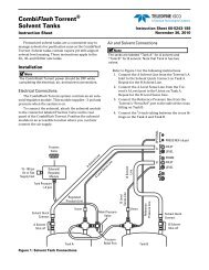
<strong>Retriever</strong> <strong>IV</strong> <strong>Fraction</strong> <strong>Collector</strong>Section 2 Installation2.1 Unpacking After removing the unit and accessories from the shippingcarton, examine them for signs of shipping damage. Be sure nointernal parts have shaken loose in transit. If there is anyshipping damage, file a claim with the delivering carrier immediately.Check the contents of the shipment against the packing slip. Ifthere are any shortages, notify Teledyne <strong>Isco</strong> immediately.NoteSave the packing materials and shipping carton until you aresure that all parts have been accounted for and the Instrumentis working satisfactorily.2.2 Set Up 1. The <strong>Retriever</strong> <strong>IV</strong> is shipped with the test tube racksinstalled. Because the test tube racks may have becomeloose during shipment, each rack should be pressed downfirmly to secure it to its shuttle. If the automatic stop featureof the <strong>Retriever</strong> <strong>IV</strong> is not to be used, the red stop testtube rack should be replaced with the white test tube rackin the accessory package.2. Remove the plastic covering from the rack sensor and supportrod assembly. Mount the sensor and support rodassembly (Figures 2-1 and 3-2) to its mounting holes on theleft side of the case top with the knurled thumbscrew.3. Remove the drop counter from the plastic bag, and mountit on the support rod so that appropriately sized tubes willpass under it unobstructed. This is done by loosening thelocking screw on the back of the drop counter assembly,positioning the entire assembly, then retightening the lockingscrew (see Figure 2-1).4. Install a black lead (tubing) connector (60-0928-001) intothe red drop former. The black lead connectors use ferrulesfor 1/16” or 1/8” OD tubing. Also included in the accessorypackage are white connectors (60-0573) which can be usedwith flexible inlet tubing.5. Next, plug the drop counter into the six-pin COUNT socketon the back panel. Final adjustment of the drop countingassembly will be necessary immediately prior to initiatingfraction collection.2-1