Retriever IV Fraction Collector User Manual - Isco
Retriever IV Fraction Collector User Manual - Isco
Retriever IV Fraction Collector User Manual - Isco

You also want an ePaper? Increase the reach of your titles
YUMPU automatically turns print PDFs into web optimized ePapers that Google loves.
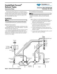
<strong>Retriever</strong> <strong>IV</strong> <strong>Fraction</strong> <strong>Collector</strong>Section 3 Operating Proceduresother hazardous effluents, because they help prevent drops fromfalling between tubes. A spring clip attaches the valve to the verticalmast. Compression fittings accept either 1 /16" (1.5 mm) or1 /8" (3 mm) OD plastic tubing.To connect the valves, plug the valve cable into the two-pinVALVE socket on the rear panel of the <strong>Retriever</strong> <strong>IV</strong>.1. Security Valve (P/N 68-2177-001) – This on-off valve isrecommended for operation at pressures below 30 psi. Useit in gravity flow and peristaltic pump systems.2. Diverter Valve (P/N 68-2177-002) – Instead of shuttingoff flow, this valve diverts it to a drain or receptacle. It istherefore suitable for higher pressure systems or applicationswhere the flow from the column should not beblocked. The valve connection labeled “IN” is the inlet. Theconnection labeled “WASTE” (normally open) goes to thedrain. The connection marked “COLLECT” (normallyclosed) goes to the fraction collector drop counter. Effluentflowing during tube changes is diverted and not collectedin any tube.3.12 Connection to aTeledyne <strong>Isco</strong>Absorbance DetectorThe information transmitted between the <strong>Retriever</strong> <strong>IV</strong> and aTeledyne <strong>Isco</strong> detector consists of tube change event marks,which appear as short negative blips, rack change event marks,which appear as short positive blips on the absorbance trace (noseparate pen is necessary), and a tube advance signal from anoptional peak separator which may be built into the detector. Thepeak separator circuit locates peaks by the change of slope in thedetector signal. At the beginning and end of each peak, the peakseparator signals the <strong>Retriever</strong> <strong>IV</strong> to change tubes, putting eachpeak into its own tubes with no dilution from preceding or succeedingbaseline effluent.NoteWhen superimposing the event mark on the absorbance curve,set the recorder baseline a little above zero. The event markblip hangs below the curve and cannot be made if the pen isalready at zero.V4 Variable Wavelength Detector or UA-6 –The V4 or UA-6 is connected to the <strong>Retriever</strong> <strong>IV</strong> with cable68-1020-213. The end of this cable with the 15-pin plug arrangedin two rows should be connected to the <strong>Retriever</strong> <strong>IV</strong>’s rear panelconnector labeled MONITOR. The other end of the cable, whichhas a nine-pin Sub D plug, should be connected to the detectorrear panel connector labeled FRACTION COLLECTORINPUT/OUTPUT.The effluent stream from the detector is then plumbed to either asecurity valve, diverter valve, or directly to the <strong>Retriever</strong> <strong>IV</strong> dropcounter.3-9