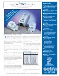
User Manual Micro-Cal⢠Model 869 - Dipl.ing. Houm AS
User Manual Micro-Cal⢠Model 869 - Dipl.ing. Houm AS
User Manual Micro-Cal⢠Model 869 - Dipl.ing. Houm AS

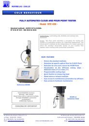
Create successful ePaper yourself
Turn your PDF publications into a flip-book with our unique Google optimized e-Paper software.
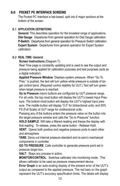
6.0 POCKET PC INTERFACE SCREENSThe Pocket PC Interface is tab-based, split into 6 major sections at thebottom of the screen.6.1 APPLICATION DEFINITIONSGeneral: This describes operation for the broadest range of applications.Dial Gauge: Departures from general operation for Dial Gauge calibration.P-Switch: Departures from general operation for Pressure Switch calibration.Expert System: Departures from general operation for Expert Systemcalibration.6.2 REAL TIME: GeneralScreen Instructions (Diagram 7):Real Time page is constantly updat<strong>ing</strong> and is used to see the output andpressure be<strong>ing</strong> applied for calibration purposes and test purposes (acts asa digital indicator).Applied Pressure Window: Displays system pressure. When “Go ToPres.” is pushed, the text will turn yellow while pressure is outside of targetcontrol band. (Required control stability for UUT.) Text will turn greenwhen target pressure is reached.Go to Pressure macro buttons are configured by UUT pressure range.For all units, the top most button will display the UUT’s lowest Input Pressure.The bottom-most button will display the UUT’s highest input pressure.The middle button will display “0.0” for bidirectional units, and 50%FS (Full Scale) of UUT range for unidirectional units.Press<strong>ing</strong> any of the buttons enters the pressure value on the button intothe target pressure window and calls the “Go to Pressure” function.HOLD SAMPLE: Will take a filtered read<strong>ing</strong> and freeze the display withthat read<strong>ing</strong>. To release, press the same button - Release Hold.VENT: Opens both positive and negative pressure ports to each otherand atmosphere.TARE: Zeros out internal pressure standard and re-zero’s mechanicalcomponents in controller.GO TO PRESSURE: Calls controller to generate pressure point set inpressure target box.HALT: Stops any process in action.MONITOR/CONTROL: Switches calibrator into monitor<strong>ing</strong> mode. Thisallows calibrator to be used as pressure measurement device.Error Graph is an auto-scal<strong>ing</strong> display of the present error of the UUT’soutput as compared to the applied pressure. The red bars on the graphrepresent the UUT’s accuracy specification limits. The labels will display12