GM4000A⢠Switch Machine - Alstom
GM4000A⢠Switch Machine - Alstom
GM4000A⢠Switch Machine - Alstom
You also want an ePaper? Increase the reach of your titles
YUMPU automatically turns print PDFs into web optimized ePapers that Google loves.
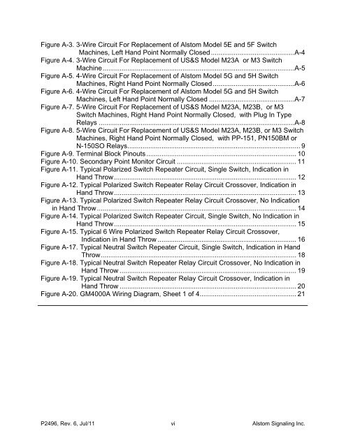
Figure A-3. 3-Wire Circuit For Replacement of <strong>Alstom</strong> Model 5E and 5F <strong>Switch</strong><strong>Machine</strong>s, Left Hand Point Normally Closed............................................A-4Figure A-4. 3-Wire Circuit For Replacement of US&S Model M23A or M3 <strong>Switch</strong><strong>Machine</strong>.....................................................................................................A-5Figure A-5. 4-Wire Circuit For Replacement of <strong>Alstom</strong> Model 5G and 5H <strong>Switch</strong><strong>Machine</strong>s, Right Hand Point Normally Closed...........................................A-6Figure A-6. 4-Wire Circuit For Replacement of <strong>Alstom</strong> Model 5G and 5H <strong>Switch</strong><strong>Machine</strong>s, Left Hand Point Normally Closed .............................................A-7Figure A-7. 5-Wire Circuit For Replacement of US&S Model M23A, M23B, or M3<strong>Switch</strong> <strong>Machine</strong>s, Right Hand Point Normally Closed, with Plug In TypeRelays .......................................................................................................A-8Figure A-8. 5-Wire Circuit For Replacement of US&S Model M23A, M23B, or M3 <strong>Switch</strong><strong>Machine</strong>s, Right Hand Point Normally Closed, with PP-151, PN150BM orN-150SO Relays........................................................................................... 9Figure A-9. Terminal Block Pinouts............................................................................... 10Figure A-10. Secondary Point Monitor Circuit ............................................................... 11Figure A-11. Typical Polarized <strong>Switch</strong> Repeater Circuit, Single <strong>Switch</strong>, Indication inHand Throw................................................................................................ 12Figure A-12. Typical Polarized <strong>Switch</strong> Repeater Relay Circuit Crossover, Indication inHand Throw................................................................................................ 13Figure A-13. Typical Polarized <strong>Switch</strong> Repeater Relay Circuit Crossover, No Indicationin Hand Throw......................................................................................................... 14Figure A-14. Typical Polarized <strong>Switch</strong> Repeater Circuit, Single <strong>Switch</strong>, No Indication inHand Throw................................................................................................ 15Figure A-15. Typical 6 Wire Polarized <strong>Switch</strong> Repeater Relay Circuit Crossover,Indication in Hand Throw ......................................................................... 16Figure A-17. Typical Neutral <strong>Switch</strong> Repeater Circuit, Single <strong>Switch</strong>, Indication in HandThrow....................................................................................................... 18Figure A-18. Typical Neutral <strong>Switch</strong> Repeater Relay Circuit Crossover, No Indication inHand Throw ............................................................................................. 19Figure A-19. Typical Neutral <strong>Switch</strong> Repeater Relay Circuit Crossover, Indication inHand Throw ............................................................................................. 20Figure A-20. GM4000A Wiring Diagram, Sheet 1 of 4................................................... 21P2496, Rev. 6, Jul/11 vi <strong>Alstom</strong> Signaling Inc.


