- Page 1: GM4000ASwitch MachineCopyright © 2
- Page 5 and 6: LIST OF EFFECTIVE PAGESP2496, GM400
- Page 7 and 8: PREFACENOTICE OF CONFIDENTIAL INFOR
- Page 9 and 10: ABOUT THE MANUALThis manual is inte
- Page 11 and 12: TopicTABLE OF CONTENTSPage1. SECTIO
- Page 13 and 14: 3.20. OPTIONAL SWITCH MACHINE AND L
- Page 15 and 16: LIST OF FIGURESFigure No. Title Pag
- Page 17 and 18: LIST OF TABLESTable No. Title PageT
- Page 19 and 20: Table 7-1. Alstom Model GM4000A Swi
- Page 21 and 22: General Description1. SECTION 1- GE
- Page 23 and 24: General DescriptionMaintenance Free
- Page 25 and 26: General Description1.4. FAIL SAFE F
- Page 27 and 28: General Description1.6. SPECIFICATI
- Page 29 and 30: General DescriptionOverload Protect
- Page 31 and 32: General DescriptionHAND CRANK(GMA50
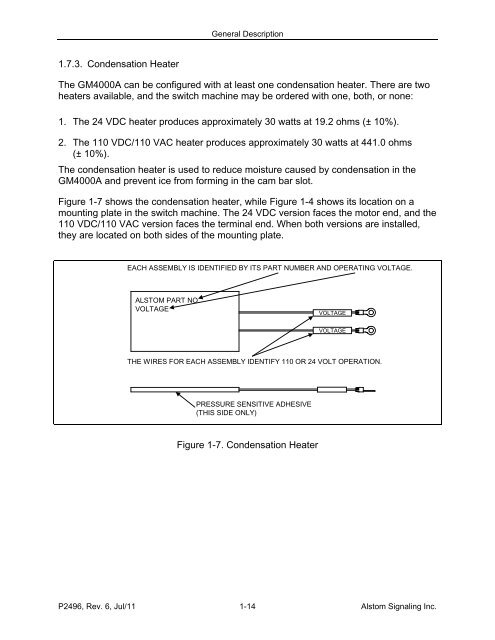
- Page 33: General Description1.7.2. Cam Bar D
- Page 37 and 38: General Description1.7.7. DC Motor
- Page 39 and 40: General Description1.7.10. Hand Cra
- Page 41 and 42: General Description1.7.13. Hand Thr
- Page 43 and 44: General Description1.7.16. Main Dri
- Page 45 and 46: General Description1.7.19. Point De
- Page 47 and 48: General Description1.7.21. Point De
- Page 49 and 50: General Description1.7.23. Throw Ba
- Page 51 and 52: General DescriptionCONFIGURATION JU
- Page 53 and 54: General DescriptionWARNINGKEEP CLEA
- Page 55 and 56: General Description1.8.5. Safety at
- Page 57 and 58: Theory of Operation2. SECTION 2 - T
- Page 59 and 60: Theory of Operation2.4. DRIVE TRAIN
- Page 61 and 62: Theory of OperationPOSITION MARKERS
- Page 63 and 64: Theory of OperationTable 2-1. Switc
- Page 65 and 66: Theory of Operation2.6.1.1. Non-Ele
- Page 67 and 68: Theory of Operation2.6.1.2. Mechani
- Page 69 and 70: Theory of OperationTable 2-3. Reset
- Page 71 and 72: Theory of OperationTable 2-4. Hand
- Page 73 and 74: Theory of Operation2.7.2. Hand Thro
- Page 75 and 76: Theory of Operation2.7.3. Local Ope
- Page 77 and 78: Installation3. SECTION 3 - INSTALLA
- Page 79 and 80: Installation3.5. COMPONENTSDependin
- Page 81 and 82: Installation3.7. INSTALLATIONDetail
- Page 83 and 84: Installation3.8. SWITCH MACHINE INS
- Page 85 and 86:
Installation3.9. SWITCH LAYOUT INSP
- Page 87 and 88:
InstallationTable 3-4. Switch Machi
- Page 89 and 90:
InstallationTable 3-4. Switch Machi
- Page 91 and 92:
InstallationTable 3-4. Switch Machi
- Page 93 and 94:
InstallationTable 3-4. Switch Machi
- Page 95 and 96:
Installation3.12. ELECTRICAL WIRING
- Page 97 and 98:
Installation3.12.1.1. Field Motor C
- Page 99 and 100:
Installation3.12.2. Controller Wiri
- Page 101 and 102:
InstallationMOTORCONTROLLERHC-11J2B
- Page 103 and 104:
Installation3.13. SWITCH MACHINE HA
- Page 105 and 106:
Installation3.14. THROW ROD INSTALL
- Page 107 and 108:
InstallationTable 3-9. Throw Rod In
- Page 109 and 110:
InstallationTable 3-10. Lock Rod Co
- Page 111 and 112:
InstallationTable 3-11. Point Detec
- Page 113 and 114:
Installation3.17. MOTOR LIMIT ADJUS
- Page 115 and 116:
Installation3.18. SWITCH MACHINE VE
- Page 117 and 118:
Installation3.20. OPTIONAL SWITCH M
- Page 119 and 120:
InstallationTable 3-15. Throw Rod P
- Page 121 and 122:
InstallationTable 3-16. Test Bar In
- Page 123 and 124:
Installation3.22. OPTIONAL SECONDAR
- Page 125 and 126:
InstallationTable 3-17. Secondary P
- Page 127 and 128:
InstallationTable 3-17. Secondary P
- Page 129 and 130:
InstallationTable 3-17. Secondary P
- Page 131 and 132:
Preventive Maintenance4. SECTION 4
- Page 133 and 134:
Preventive MaintenanceNOTEOne opera
- Page 135 and 136:
Preventive Maintenance4.3.2. After
- Page 137 and 138:
Preventive Maintenance4.4. EVERY 75
- Page 139 and 140:
Preventive Maintenance4.5. MONTHLY
- Page 141 and 142:
Preventive Maintenance4.5.1.1. Hand
- Page 143 and 144:
Preventive Maintenance4.5.2. Hand T
- Page 145 and 146:
Preventive MaintenanceTable 4-5. Ha
- Page 147 and 148:
Preventive Maintenance4.5.4. Second
- Page 149 and 150:
Preventive Maintenance4.5.5. Point
- Page 151 and 152:
Preventive MaintenanceTable 4-9. Na
- Page 153 and 154:
Preventive MaintenanceTable 4-9. Na
- Page 155 and 156:
Preventive MaintenanceTable 4-10. W
- Page 157 and 158:
Preventive Maintenance4.5.7. Latch
- Page 159 and 160:
Preventive MaintenanceTable 4-12. I
- Page 161 and 162:
Preventive MaintenanceTable 4-12. I
- Page 163 and 164:
Preventive MaintenanceTable 4-13. B
- Page 165 and 166:
Preventive Maintenance4.9. AS REQUI
- Page 167 and 168:
Preventive Maintenance4.9.2. Point
- Page 169 and 170:
Preventive MaintenanceStepTable 4-1
- Page 171 and 172:
Preventive MaintenanceTable 4-18. G
- Page 173 and 174:
Troubleshooting5. SECTION 5 - TROUB
- Page 175 and 176:
Troubleshooting5.3.2. Symptoms Noti
- Page 177 and 178:
Troubleshooting5.3.3. Symptoms Noti
- Page 179 and 180:
Troubleshooting5.3.4. Controller LE
- Page 181 and 182:
Troubleshooting5.3.4.2. Enhanced Mo
- Page 183 and 184:
Troubleshooting5.3.4.2.2. Motor Fau
- Page 185 and 186:
Corrective Maintenance6. SECTION 6
- Page 187 and 188:
Corrective Maintenance6.2.2. Cross
- Page 189 and 190:
Corrective MaintenanceTable 6-3. Co
- Page 191 and 192:
Corrective MaintenanceTable 6-4. DC
- Page 193 and 194:
Corrective Maintenance6.2.5. Main D
- Page 195 and 196:
Corrective MaintenanceTable 6-5. Ma
- Page 197 and 198:
Corrective Maintenance6.2.7. Cam Ba
- Page 199 and 200:
Corrective Maintenance6.2.8. Hand T
- Page 201 and 202:
Corrective Maintenance6.2.9. Hand C
- Page 203 and 204:
Corrective MaintenanceTable 6-9. Ha
- Page 205 and 206:
Corrective MaintenanceStepTable 6-1
- Page 207 and 208:
Corrective MaintenanceStepTable 6-1
- Page 209 and 210:
Corrective MaintenanceTable 6-10. H
- Page 211 and 212:
Corrective Maintenance6.2.12. Lock
- Page 213 and 214:
Corrective MaintenanceTable 6-13. P
- Page 215 and 216:
Corrective MaintenanceTable 6-14. P
- Page 217 and 218:
Corrective MaintenanceTable 6-14. P
- Page 219 and 220:
Corrective MaintenanceTable 6-14. P
- Page 221 and 222:
Corrective Maintenance6.2.14. Point
- Page 223 and 224:
Corrective Maintenance6.2.15. Point
- Page 225 and 226:
Corrective Maintenance6.2.16. Point
- Page 227 and 228:
Corrective Maintenance6.2.17. Throw
- Page 229 and 230:
Corrective Maintenance6.2.18. Throw
- Page 231 and 232:
Corrective Maintenance6.2.19. Conde
- Page 233 and 234:
Corrective MaintenanceTable 6-21. M
- Page 235 and 236:
Parts Catalog7. SECTION 7 - PARTS C
- Page 237 and 238:
Parts CatalogNOTE 1:- STAMP NAME PL
- Page 239 and 240:
Parts Catalog2.006.50 7.5020.00 2.8
- Page 241 and 242:
Parts CatalogABCDSWITCH MACHINESHEE
- Page 243 and 244:
Parts Catalog29LOCK RODCOMPLETEDETE
- Page 245 and 246:
Parts CatalogTable 7-1. Alstom Mode
- Page 247 and 248:
Parts CatalogTable 7-1. Alstom Mode
- Page 249 and 250:
Parts CatalogTable 7-1. Alstom Mode
- Page 251 and 252:
Parts CatalogTable 7-1. Alstom Mode
- Page 253 and 254:
Parts CatalogTable 7-2. GM4000A Con
- Page 255 and 256:
Parts CatalogFigure 7-2. Alstom Mod
- Page 257 and 258:
Parts CatalogTable 7-3. Alstom Mode
- Page 259 and 260:
Parts CatalogDBACEGFHFigure 7-3. To
- Page 261 and 262:
Parts CatalogTable 7-6. Alstom Mode
- Page 263 and 264:
DrawingsA. APPENDIX A - DRAWINGSA.1
- Page 265 and 266:
DrawingsA.2.2.3-Wire Configuration
- Page 267 and 268:
DrawingsA.2.3.3-Wire Configuration
- Page 269 and 270:
Drawings16 to 160 VDCOR85 to 140 VA
- Page 271 and 272:
DrawingsFigure A-8 shows typical ci
- Page 273 and 274:
DrawingsA.2.7.Secondary Point Monit
- Page 275 and 276:
DrawingsTypical Polarized Switch Re
- Page 277 and 278:
DrawingsTypical Polarized Switch Re
- Page 279 and 280:
DrawingsA.2.9.Typical Neutral Switc
- Page 281 and 282:
DrawingsTypical Neutral Switch Repe
- Page 283 and 284:
DrawingsA.2.10. GM4000A Wiring Diag
- Page 285 and 286:
DrawingsFigure A-20. GM4000A Wiring
- Page 288:
FOR QUESTIONS AND INQUIRIES, CONTAC