S5600 Installation Instructions - Efco
S5600 Installation Instructions - Efco
S5600 Installation Instructions - Efco

Create successful ePaper yourself
Turn your PDF publications into a flip-book with our unique Google optimized e-Paper software.
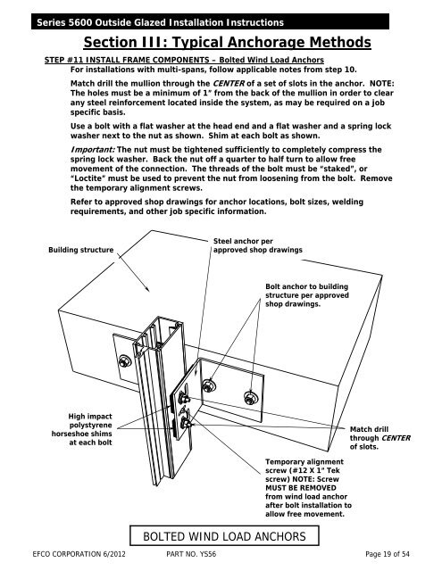
Series 5600 Outside Glazed <strong>Installation</strong> <strong>Instructions</strong>Section III: Typical Anchorage MethodsSTEP #11 INSTALL FRAME COMPONENTS – Bolted Wind Load AnchorsFor installations with multi-spans, follow applicable notes from step 10.Match drill the mullion through the CENTER of a set of slots in the anchor. NOTE:The holes must be a minimum of 1” from the back of the mullion in order to clearany steel reinforcement located inside the system, as may be required on a jobspecific basis.Use a bolt with a flat washer at the head end and a flat washer and a spring lockwasher next to the nut as shown. Shim at each bolt as shown.Important: The nut must be tightened sufficiently to completely compress thespring lock washer. Back the nut off a quarter to half turn to allow freemovement of the connection. The threads of the bolt must be “staked”, or“Loctite” must be used to prevent the nut from loosening from the bolt. Removethe temporary alignment screws.Refer to approved shop drawings for anchor locations, bolt sizes, weldingrequirements, and other job specific information.Building structureSteel anchor perapproved shop drawingsBolt anchor to buildingstructure per approvedshop drawings.High impactpolystyrenehorseshoe shimsat each boltMatch drillthrough CENTERof slots.BOLTED WIND LOAD ANCHORSTemporary alignmentscrew (#12 X 1” Tekscrew) NOTE: ScrewMUST BE REMOVEDfrom wind load anchorafter bolt installation toallow free movement.EFCO CORPORATION 6/2012 PART NO. YS56 Page 19 of 54