S5600 Installation Instructions - Efco
S5600 Installation Instructions - Efco
S5600 Installation Instructions - Efco

You also want an ePaper? Increase the reach of your titles
YUMPU automatically turns print PDFs into web optimized ePapers that Google loves.
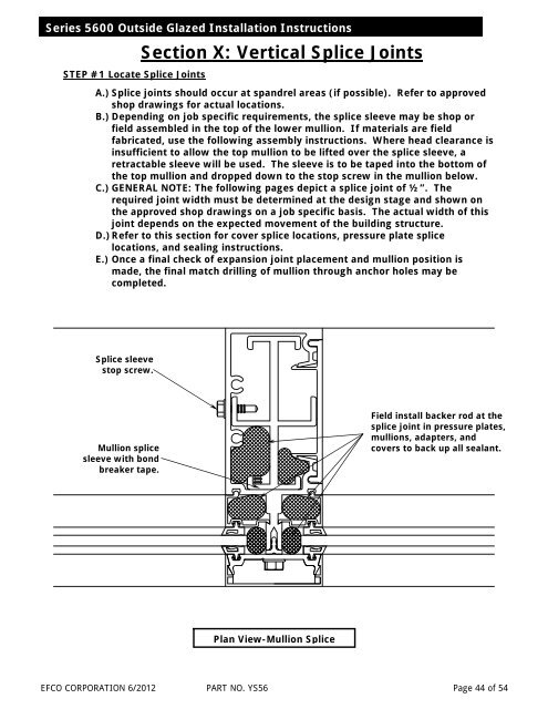
Series 5600 Outside Glazed <strong>Installation</strong> <strong>Instructions</strong>STEP #1 Locate Splice JointsSection X: Vertical Splice JointsA.) Splice joints should occur at spandrel areas (if possible). Refer to approvedshop drawings for actual locations.B.) Depending on job specific requirements, the splice sleeve may be shop orfield assembled in the top of the lower mullion. If materials are fieldfabricated, use the following assembly instructions. Where head clearance isinsufficient to allow the top mullion to be lifted over the splice sleeve, aretractable sleeve will be used. The sleeve is to be taped into the bottom ofthe top mullion and dropped down to the stop screw in the mullion below.C.) GENERAL NOTE: The following pages depict a splice joint of ½”. Therequired joint width must be determined at the design stage and shown onthe approved shop drawings on a job specific basis. The actual width of thisjoint depends on the expected movement of the building structure.D.) Refer to this section for cover splice locations, pressure plate splicelocations, and sealing instructions.E.) Once a final check of expansion joint placement and mullion position ismade, the final match drilling of mullion through anchor holes may becompleted.Splice sleevestop screw.Mullion splicesleeve with bondbreaker tape.Field install backer rod at thesplice joint in pressure plates,mullions, adapters, andcovers to back up all sealant.Plan View-Mullion SpliceEFCO CORPORATION 6/2012 PART NO. YS56 Page 44 of 54