Marvell PXA27x Processor Family
PXA27x Design Guide - Marvell
PXA27x Design Guide - Marvell
You also want an ePaper? Increase the reach of your titles
YUMPU automatically turns print PDFs into web optimized ePapers that Google loves.
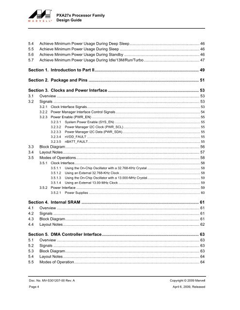
<strong>PXA27x</strong> <strong>Processor</strong> <strong>Family</strong><br />
Design Guide<br />
5.4 Achieve Minimum Power Usage During Deep Sleep................................................................ 46<br />
5.5 Achieve Minimum Power Usage During Sleep ......................................................................... 46<br />
5.6 Achieve Minimum Power Usage During Standby ..................................................................... 46<br />
5.7 Achieve Minimum Power Usage During Idle/13M/Run/Turbo................................................... 47<br />
Section 1. Introduction to Part II....................................................................................... 49<br />
Section 2. Package and Pins ............................................................................................ 51<br />
Section 3. Clocks and Power Interface ............................................................................ 53<br />
3.1 Overview ................................................................................................................................... 53<br />
3.2 Signals ...................................................................................................................................... 53<br />
3.2.1 Clock Interface Signals................................................................................................................... 53<br />
3.2.2 Power Manager Interface Control Signals...................................................................................... 54<br />
3.2.3 Power Enable (PWR_EN) .............................................................................................................. 55<br />
3.2.3.1 System Power Enable (SYS_EN) ............................................................................................ 55<br />
3.2.3.2 Power Manager I2C Clock (PWR_SCL)................................................................................... 55<br />
3.2.3.3 Power Manager I2C Data (PWR_SDA).................................................................................... 55<br />
3.2.3.4 nVDD_FAULT .......................................................................................................................... 55<br />
3.2.3.5 nBATT_FAULT......................................................................................................................... 55<br />
3.3 Block Diagram........................................................................................................................... 56<br />
3.4 Layout Notes ............................................................................................................................. 57<br />
3.5 Modes of Operations................................................................................................................. 58<br />
3.5.1 Clock Interface................................................................................................................................ 58<br />
3.5.1.1 Using the On-Chip Oscillator with a 32.768-KHz Crystal ......................................................... 58<br />
3.5.1.2 Using an External 32.768-KHz Clock ....................................................................................... 58<br />
3.5.1.3 Using the On-Chip Oscillator with a 13.000-MHz Crystal......................................................... 59<br />
3.5.1.4 Using an External 13.00-MHz Clock ........................................................................................ 59<br />
3.5.2 Power Interface .............................................................................................................................. 59<br />
3.5.2.1 Power Supplies ........................................................................................................................ 60<br />
Section 4. Internal SRAM .................................................................................................. 61<br />
4.1 Overview ................................................................................................................................... 61<br />
4.2 Signals ...................................................................................................................................... 61<br />
4.3 Block Diagram........................................................................................................................... 61<br />
4.4 Layout Notes ............................................................................................................................. 62<br />
Section 5. DMA Controller Interface................................................................................. 63<br />
5.1 Overview ................................................................................................................................... 63<br />
5.2 Signals ...................................................................................................................................... 63<br />
5.3 Block Diagram........................................................................................................................... 63<br />
5.4 Layout Notes ............................................................................................................................. 64<br />
5.5 Modes of Operation................................................................................................................... 64<br />
Doc. No. MV-S301207-00 Rev. A<br />
Page 4<br />
Copyright © 2009 <strong>Marvell</strong><br />
April 6, 2009, Released


